


") She decides to die in spite of Dr. Bottles
She decides to die in spite of Dr. Bottles Sad young lady") The widow
The widow
Sad young lady") She finds that exercise does not improve her spirits
She finds that exercise does not improve her spirits Lady standing in black dress") The widow - standing
The widow - standing
Lady standing in black dress") Man seated sideways on a chair
Man seated sideways on a chair") Miss Babbles, the authoress, calls and reads aloud
Miss Babbles, the authoress, calls and reads aloud Maid putting shoe on while young lady looks in mirror") She finds some consolation in her mirror
She finds some consolation in her mirror
Maid putting shoe on while young lady looks in mirror") Page Frame
Page Frame 1. Key-rocker.
2. Abstract.
3. Abstract-lever.
4. Flange.
5. Action-rail.
6. Wip...") Standard American upright action
Standard American upright action
1. Key-rocker. 2. Abstract. 3. Abstract-lever. 4. Flange. 5. Action-rail. 6. Wippen. 7. Jack. 8. Jack-spring. 9. Check. 10. Check-wire. 11. Bridle-wire. 12. Tip of bridle-tape. 13. Bridle-tape. 14. Back-stop. 15. Regulating rail. 16. Regulating button. 17. Regulating screw. 18. Hammer-butt. 19. Hammer-shank. 20. Hammer-molding. 21. Hammer-head. 22. Hammer-rail. 23. Hammer-butt spring. 24. Hammer-spring rail. 25. Damper-spoon. 26. Damper-lifting rod. 27. Damper-lever. 28. Damper-lever spring. 29. Damper-wire. 30. Damper-block. 31. Damper-head. 32. String. 33. Continuous brass hammer-butt flange. Upright action showing lost-motion device, metallic regulating rail support, capstan screw, jack reg...") Upright action showing lost-motion device
Upright action showing lost-motion device
Upright action showing lost-motion device, metallic regulating rail support, capstan screw, jack regulating rail and metallic action brackets. 34. Hammer-rail lifter-wire. 35. Hammer-rail swing-lever. 36. Hammer-rail lifter rod. 37. Lifter-rod lever. 38. Compensation-lever. 39. Capstan-screw. 40. Rail for limiting return movement of jack. 41. Metallic regulating rail support. Grand pianoforte action with metallic action and damper frames, sostenuto pedal device and hammer ...") Grand pianoforte action with metallic action and damper frames
Grand pianoforte action with metallic action and damper frames
Grand pianoforte action with metallic action and damper frames, sostenuto pedal device and hammer swinging soft pedal attachment. 22. Sostenuto pedal-rod. 23. Attachment to damper-lever engaging with sostenuto pedal-rod. 24. Metallic action and damper-brackets. 25. Hammer swing-rail and cushion. 26. Hammer swing-rail rod. 27. Hammer swing-rail lifter. 28. Lifter-rod. 29. Lost motion compensating levers. 30. Lost motion compensating levers.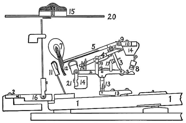 Standard modern American grand action
1. Key. 2. Wippen. 3. Jack. 4. Escapement lever. 5. Hammer-shank. 6. Roller. 7. Hammer-head. 8. Jack-regulating button. 9. Regulating button to limit rise of escapement lever. 10. Hammer-butt. 11. Check. 12. Molded tail of hammer-head to engage with check. 13. Key-rocker and sticker connecting wippen and key. 14. Action-rails. 15. Damper-head. 16. Damper operating device. 17. Device to limit travel of jack. 18. Regulating device for escapement lever. 19. Separate springs for jack and escapement lever. 20. String. 21. Flanges.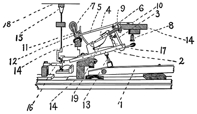 Double repetition action of Sebastian Erard as used by S. & P. Erard, Paris
1. Key. 2. Wippen. 3. Jack. 4. Escapement lever. 5. Hammer-shank. 6. Roller. 7. Hammer-head. 8. Jack regulating button. 9. Regulating button to limit rise of escapement lever. 10. Hammer-butt. 11. Check. 12. Felt cushion to engage with check. 13. Sticker connecting key and wippen. 14. Action-rails. 15. Damper-head. 16. Damper operating device. 17. Device to limit travel of jack. 18. String. 19. Spring (v-shaped) for escapement lever and jack. 1. Key.
2. Wippen.
3. Jack.
4. Escapement lever.
5. Hammer-shank.
6. Hammer-b...") The Erard grand action modified by Herz
The Erard grand action modified by Herz
1. Key. 2. Wippen. 3. Jack. 4. Escapement lever. 5. Hammer-shank. 6. Hammer-butt notch. 7. Hammer-head. 8. Jack regulating button. 9. Regulating button to limit rise of escapement lever. 10. Hammer-butt. 11. Check. 12. Molded tail of hammer-head to engage with check. 13. Capstan-screw connecting key and wippen. 14. Action-rails. 15. Damper-head. 16. Damper-operating device. 17. Device to limit travel of jack. 18. Regulating device for escapement lever. 19. Springs (2) for escapement lever and jack. 20. String. 21. Flange., Streicher Viennese escapement (1794) (757 visits) 1. Key.
2. Jack.
3. Jack-operating spring.
4. Cushion limiting rebound of jack.
5...") Action by Andreas and Nanette (Stein), Streicher Viennese escapement (1794)
Action by Andreas and Nanette (Stein), Streicher Viennese escapement (1794)
1. Key. 2. Jack. 3. Jack-operating spring. 4. Cushion limiting rebound of jack. 5. Button and screw regulating escapement of hammer. 6. Hammer-butt and operating face. 7. Hammer-butt pivot. 8. Hammer-shank. 9. Hammer-head. 10. Check. 11. Damper-lifter. 12. Damper-head. 13. Action-rails. (771 visits) 1. Key.
2. Jack.
3. Jack operating spring.
4. Rail and cushion limiting travel of jac...") English direct lever grand action, developed by Broadwood from Backers (1884)
English direct lever grand action, developed by Broadwood from Backers (1884)
1. Key. 2. Jack. 3. Jack operating spring. 4. Rail and cushion limiting travel of jack. 5. Button and screw regulating escapement of hammer. 6. Hammer-butt with operating notch. 7. Hammer-butt flange. 8. Hammer-shank. 9. Hammer-head. 10. Check. 13. Action-rails. 1. Key.
2. Jack.
3. Jack-operating spring.
4. Cushion limiting rebound of jack.
5...") Cristofori’s action in its final form
Cristofori’s action in its final form
1. Key. 2. Jack. 3. Jack-operating spring. 4. Cushion limiting rebound of jack. 5. Under-hammer. 6. Hammer-butt. 7. Hinge of hammer-butt. 8. Hammer-shank. 9. Hammer head. 10. Check. 11. Damper-lifter. 12. Damper-head. 13. Action-beam. 14. Wrest-plank. 15. Tuning pins. 16. Bearing-bridge. 17. String. (711 visits)") Iron plate for upright pianoforte with Agraffes (Mehlin patents)
Iron plate for upright pianoforte with Agraffes (Mehlin patents)") Arrangement of iron plate, braces and scale of parlor size grand pianoforte
Arrangement of iron plate, braces and scale of parlor size grand pianoforte") Iron plate for upright pianoforte fitted with Capo D’astro bar
Iron plate for upright pianoforte fitted with Capo D’astro bar Sketch of iron plate for concert grand, showing general arrangement of braces, belly-bridges and sys...") Sketch of iron plate for concert grand
Sketch of iron plate for concert grand
Sketch of iron plate for concert grand, showing general arrangement of braces, belly-bridges and system of bolts for fastening to case. A—B. Hammer line. 1. Body of plate. 2. Bass bridge. 3. Continuous treble bridge. 4. Agraffes. 5. Capo d’astro bar. Plate is cast in one piece and scale is overstrung. Back view of upright pianoforte, Knabe patents, showing ribbing of sound-board and construction of b...") Back view of upright pianoforte
Back view of upright pianoforte
Back view of upright pianoforte, Knabe patents, showing ribbing of sound-board and construction of back framing.") Jonas Chickering’s full solid cast grand metal plate
Jonas Chickering’s full solid cast grand metal plate A. Continuous bent rim.
B. Wooden struts.
C. Iron shoe holding struts and connecting with iron pla...") Modern method og grand pianoforte case construction
Modern method og grand pianoforte case construction
A. Continuous bent rim. B. Wooden struts. C. Iron shoe holding struts and connecting with iron plate. D. Main beam. The farmer sells his crop of wheat to the grain-dealer, and carts it, say, to Brandon, where the pur...") C. P. R. grain elevator at Fort William, Ontario
C. P. R. grain elevator at Fort William, Ontario
The farmer sells his crop of wheat to the grain-dealer, and carts it, say, to Brandon, where the purchaser takes delivery of it at his elevator. Let us examine this thing somewhat minutely, taking by way of illustration one of the elevators belonging to the Canadian Pacific Railway Company at Montreal. It is a medium-sized one, having capacity for storing about 600,000 bushels of grain. The same company’s elevators at Fort William and Port Arthur are much larger, having capacity for 1,500,000 bushels. In Chicago and Buffalo there are elevators of three millions of bushels capacity; but, whether larger or smaller, in their main features they are all alike. The elevator is a wooden structure of great strength. Its massive stone foundations rest on piles imbedded in concrete. The framework is so thoroughly braced and bolted together as to give it the rigidity of a solid cube, enabling it to resist the enormous pressure to which it is subjected when filled with 18,000 tons of wheat. The building is 210 feet long, 80 feet wide, and 142 feet in height from basement to the peak of the roof. Including the steam-engine (built at the C. P. R. works) of 240 horse-power, the entire cost of this elevator was $150,000. It consists of three distinct compartments—for receiving, storing, and delivering grain. On the ground floor are two lines of rails by which the cars have ingress and egress. The general appearance of this flat is that of a bewildering array of ponderous posts and beams, shafting, cog-wheels, pulleys and belts, blocks and tackle, chutes, and the windlasses for hauling in and out the cars, for a locomotive with its dangerous sparks may not cross the threshold. Beneath this, in the basement, are the receiving tanks, thirty-five feet apart from centre to centre, corresponding to the length of the cars. Of these there are nine, enabling that number of cars to be simultaneously unloaded. This is quickly done by a shovel worked by machinery, with the aid of two men, the grain falling through an iron grating in the floor into the tank. The elevator has nine “legs.” The leg is an upright box, 12 inches by 24 inches, extending from the bottom of the tank to the top of the building; inside of it is a revolving belt with buckets attached 15½ inches apart. The belt is 256 feet long, and as it makes 36 revolutions per minute, each bucket containing one-third of a bushel, each leg is able to raise 5,250 bushels per hour. A car is unloaded and its contents hoisted into the upper regions in fifteen minutes. When all the legs are at work 30,000 bushels are handled in an hour. Last of the Clipper Passenger Packets, 1854.
The clipper “packet ship” was a vast improvement...") 'Great Republic'
'Great Republic'
Last of the Clipper Passenger Packets, 1854. The clipper “packet ship” was a vast improvement on the ordinary sailing ship. It had just reached its highest point of development when the ocean steamship first made its appearance. It was to the upper strata of the travelling community, sixty years ago, the counterpart of the express steamer of to-day. The packet-ship was built for fast sailing, with very fine lines, was handsomely fitted up and furnished, was exceedingly well found in eatables and drinkables, and carried a great spread of canvas. To see one of these ships under full sail was a [Pg 27]sight to be remembered—a rare sight, inasmuch as all the conditions of wind and water necessary for the display of every stitch of canvas are seldom met with in the North Atlantic. They not unfrequently crossed in fourteen or fifteen days. In winter they might be three months on a single voyage, but their average would be from twenty-five to thirty days. Paddle-wheels for driving boats through the water were used long before steam-engines were thought o...") Horse-boat at Empy’s Ferry, Osnabruck, Ontario
Horse-boat at Empy’s Ferry, Osnabruck, Ontario
Paddle-wheels for driving boats through the water were used long before steam-engines were thought of. They were worked by hand and foot-power without, however, any advantage over the old-fashioned oar. The horse-boat, in a variety of forms, has been in use for many years, and is not yet quite obsolete. In its earlier form two horses, one on each side of a decked scow, were hitched to firmly braced upright posts at which they tugged for all they were worth without ever advancing beyond their noses, but communicating motion to the paddle-wheels by the movable platform on which they trod. For larger boats four or five horses were harnessed to horizontal bars converging towards the centre, and moved around the deck in a circle, the paddles receiving their impulse through a set of cog-wheels.