


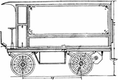
 Synnestvedt 2-Ton Truck
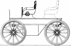 Hercules, Model 140
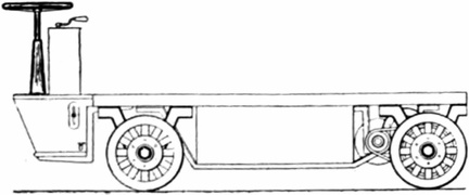 Hercules, Model 144
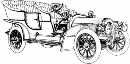 Hill Touring Car, 35 H.P
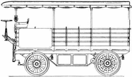 Hercules, Model 121
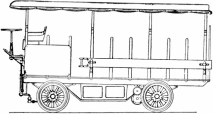 Hercules, Model 128
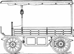 Hercules, Model 139
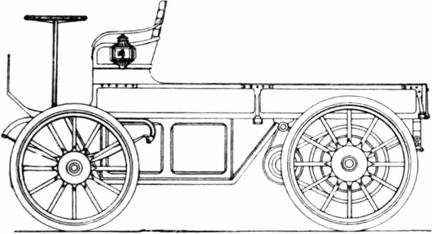 Hercules, Model 106
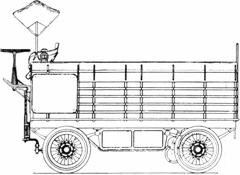 Hercules, Model 113
 Hercules, Model 120
 Hercules, Model 102
 Hercules, Model 103
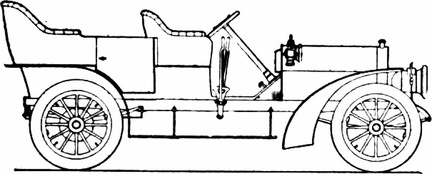 Pennsylvania, 35 H.P. Pennsylvania Auto Motor Co., Phil., Pa.
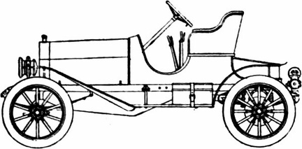 Marion Model 7, 22–24 H.P
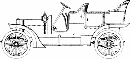 Wolfe, Model A, 24 H.P
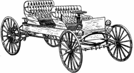 Buggyabout, Model C, 14 H.P
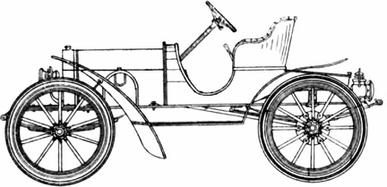 Aurora, Model 'A,' 14–16 H.P
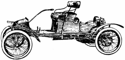 Waltham-Orient, Model B R., 4 H.P
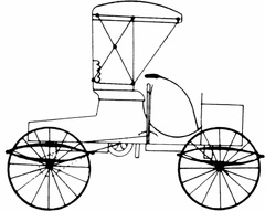 Albany Run-a-bout, Model 2, 4–6 H. P
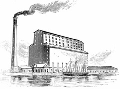 C. P. R. grain elevator at Fort William, Ontario
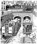 The tunnels
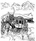 The Stage coach
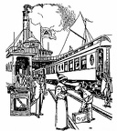 The Train Ferry
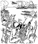 An observation train
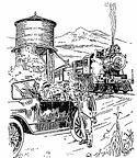 The water tank
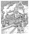 The Round House
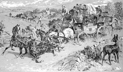 Horses in a heap, Leader down, Wheelers falling over him
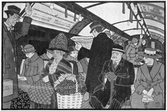 The Tube
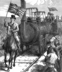 The first Railway Journey in England
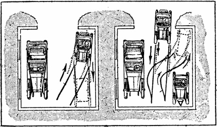 Methods to get to the right place in a garage
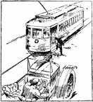 Overtaking a tram
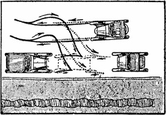 Parking
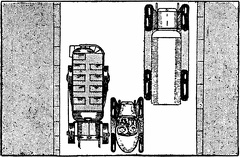 Room to pass
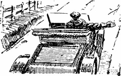 Turn Signal
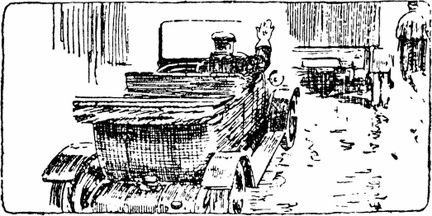 Stop Signal
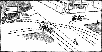 Swerving at intersections
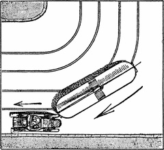 Cars and Trams
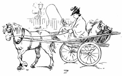 Lady driving in a horse and cart
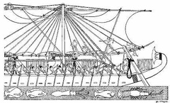 Egyptian Ships in the time of Hatasu
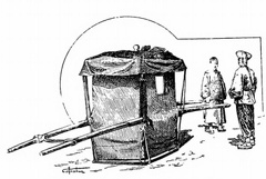 A Chinese sedan chair and bearers
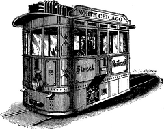 A Steam Street Railway Motor
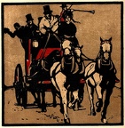 Coaching
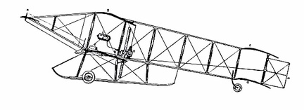 The Farman Biplane
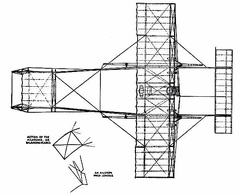 The Farman Biplane - top view
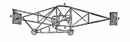 The Curtiss Biplane
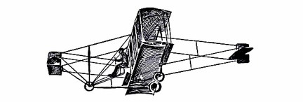 The Curtiss Biplane making a turn
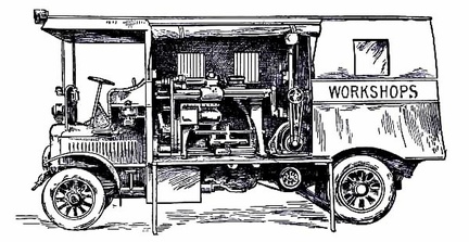 Travelling workshop for the repair of military aeroplanes
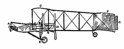 The Voisin Biplane
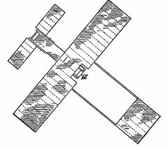 The Voisin Biplane - top view
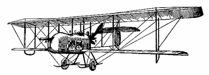 The Vickers
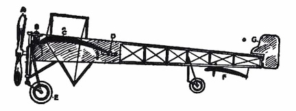 The Bleriot Monoplane
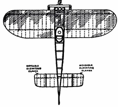 The Bleriot Monoplane - top view
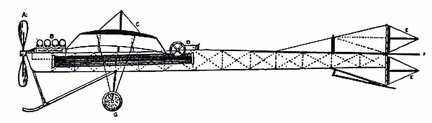 The Antoinette Monoplane
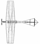 The Antoinette Monoplane - top view
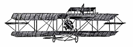 The Curtiss Biplane in flight
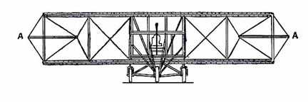 The Curtiss Biplane front view
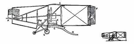 The Cody Biplane
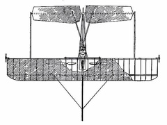 The Cody Biplane from above
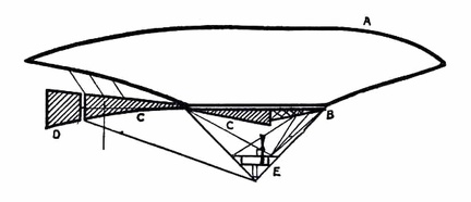 Semi-rigid Airship
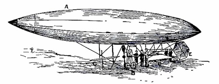 Santos-Dumont’s Airship