


 The new bridge at Poughkeepsie has three of these cantilevers, connected by two fixed spans, as show...") Erection of a Cantilever
Erection of a Cantilever
The new bridge at Poughkeepsie has three of these cantilevers, connected by two fixed spans, as shown in the illustration. The fixed spans have horizontal lower chords, and really extend beyond each pier and up the inclined portions, to where the bottom chord of the cantilever is horizontal. At these points the junctions between the spans are made, and arranged in such a way, by means of movable links, that expansion and contraction due to changes of temperature can take place. The fixed spans are 525 feet long. Their upper chord, where the tracks are placed, is 212 feet above water. These spans required stagings to build them upon. These stagings were 220 feet above water, and rested on piles, driven through 60 feet of water and 60 feet of mud, making the whole height of the temporary staging 332 feet, or within 30 feet of the height of Trinity Church steeple, in New York. The[35] time occupied in building one of these stagings and then erecting the steel-work upon it was about four months. The cantilever spans were erected without any stagings at all below, and entirely from the two overhead travelling scaffolds, shown in the engraving. These scaffolds were moved out daily from the place of beginning over the piers, until they met in the centre. The workmen hoisted up the different pieces of steel from a barge in the river below and put them into place, using suspended planks to walk upon. The time saved by this method was so great that one of these spans of 548 feet long was erected in less than four weeks, or one-seventh of the time which would have been required if stagings had been used.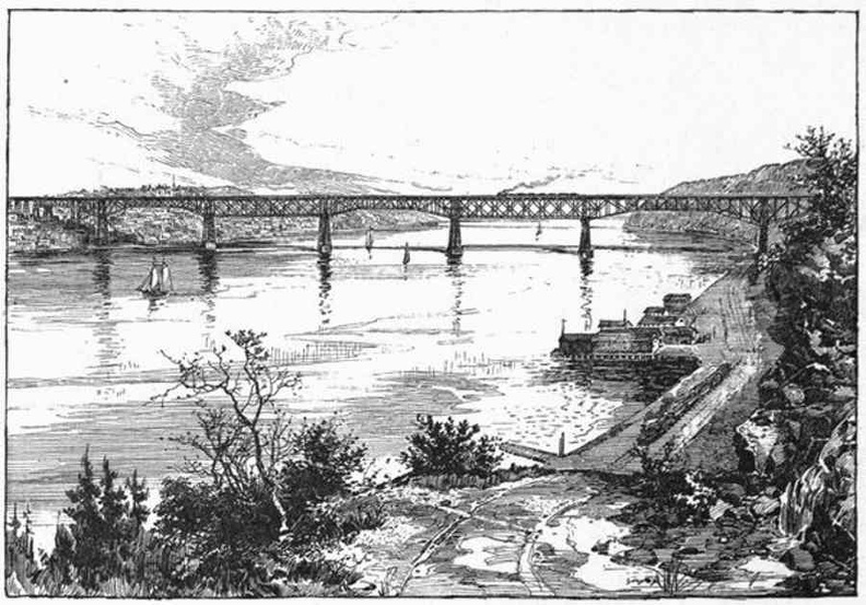
 (1119 visits) The most notable invention of latter days in bridge construction is that of the cantilever bridge, w...") View of Thomas Pope's Proposed Cantilever (1810)
View of Thomas Pope's Proposed Cantilever (1810)
The most notable invention of latter days in bridge construction is that of the cantilever bridge, which is a system devised to dispense with staging, or false works, where from the great depth, or the swift current, of the river, this would be difficult, or, as in the case of the Niagara River, impossible to make. The first design of which we have any record was that of a bridge planned by Thomas Pope, a ship carpenter of New York, who, in 1810, published a book giving his designs for an arched bridge of timber across the North River at Castle Point, of 2,400 feet span. Mr. Pope called this an arch, but his description clearly shows it to have been what we now call a cantilever. As was the fashion of the day, he indulged in a poetical description: "Like half a Rainbow rising on yon shore, While its twin partner spans the semi o'er, And makes a perfect whole that need not part Till time has furnish'd us a nobler art."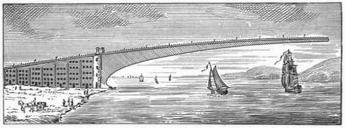
 On the prairies of the West the road-bed is thrown up from ditches on each side, either by men with ...") Steam Excavator
Steam Excavator
On the prairies of the West the road-bed is thrown up from ditches on each side, either by men with wheelbarrows and carts, or by means of a ditching-machine, which can move 3,000 yards of earth daily. In this case the track follows immediately after the embankment, and the men live in cars fitted up as boarding-shanties, and moved forward as fast as required. In all countries, old and new, mountainous and level, the rule should be to keep the level of track ...") Snow-sheds, Selkirk Mountains, Canadian Pacific
Snow-sheds, Selkirk Mountains, Canadian Pacific
In all countries, old and new, mountainous and level, the rule should be to keep the level of track well above the surface of the ground, in order to insure good drainage and freedom from snow-drifts. The question of avoidance of obstruction by snow is a very serious one upon the Rocky Mountain lines, and they could not be worked without the device of snow-sheds—another purely American invention. There are said to be six miles of staunchly built snow-sheds on the Canadian Pacific and sixty miles on the Central Pacific Railway. The quantity of snow falling is enormous, sometimes amounting to 250,000 cubic yards, weighing over 100,000 tons, in one slide. It is stated by the engineers of the Canadian Pacific, that the force of the air set in motion by these avalanches has mown down large trees, not struck by the snow itself. Their trunks, from one to two feet in diameter, remain, split as if struck by lightning. Another American invention is the switchback. By this plan the length of line required to ease the g...") A Switchback
A Switchback
Another American invention is the switchback. By this plan the length of line required to ease the gradient is obtained by running backward and forward in a zigzag course, instead of going straight up the mountain. As a full stop has to be made at the end of every piece of line, there is no danger of the train running away from its brakes. This device was first used among the hills of Pennsylvania over forty years ago, to lower coal cars down into the Nesquehoning Valley. It was afterwards used on the Callao, Lima, and Oroya Railroad in Peru, by American engineers, with extraordinary daring and skill. It was employed to carry the temporary tracks of the Cascade Division of the Northern Pacific Railroad over the "Stampede" Pass, with grades of 297 feet per mile, while a tunnel 9,850 feet long was being driven through the mountains. Equally valuable improvements were made in cars, both for passengers and freight. Instead of the fou...") A Sharp Curve—Manhattan Elevated Railway, 110th Street, New York
A Sharp Curve—Manhattan Elevated Railway, 110th Street, New York
Equally valuable improvements were made in cars, both for passengers and freight. Instead of the four-wheeled English car, which on a rough track dances along on three wheels, we owe to Ross Winans, of Baltimore, the application of a pair of four-wheeled swivelling trucks, one under each end of the car, thus enabling it to accommodate itself to the inequalities of a rough track and to follow its locomotive around the sharpest curves. There are, on our main lines, curves of less than 300 feet radius, while, on the Manhattan Elevated, the largest passenger traffic in the world is conducted around curves of less than 100 feet radius. There are few curves of less than 1,000 feet radius on European railways.") Locomotive of To-day
Locomotive of To-day") Rail Making
Rail Making") The Last Span - ready to join
The Last Span - ready to join About 1820, the State of Illinois was being rapidly settled by people from the eastern states. Prior...") Pioneer Wagons
Pioneer Wagons
About 1820, the State of Illinois was being rapidly settled by people from the eastern states. Prior to this time, very few white settlements had been made in the state. These early pioneers, drawn from the population of the eastern states, were composed of almost all nationalities. They pushed their way across the mountains of Pennsylvania and Virginia in crude wagons, drawn by oxen, bringing with them their household goods and a few milk cows. About 1820, the State of Illinois was being rapidly settled by people from the eastern states. Prior...") Early Settler Homestead
Early Settler Homestead
About 1820, the State of Illinois was being rapidly settled by people from the eastern states. Prior to this time, very few white settlements had been made in the state. These early pioneers, drawn from the population of the eastern states, were composed of almost all nationalities. They pushed their way across the mountains of Pennsylvania and Virginia in crude wagons, drawn by oxen, bringing with them their household goods and a few milk cows. They came into Illinois, built new homes, and laid out new fields on the broad, unsettled prairies. In April, 1869, a charter was granted by the state of Illinois to the East St. Louis Stock Yards Com...") Cattle
Cattle
In April, 1869, a charter was granted by the state of Illinois to the East St. Louis Stock Yards Company. This company was authorized to issue stock to an amount not to exceed $200,000. The original charter of the company, which later operated the National Stock Yards, fixed the capital stock thereof at $1,000,000, which was, subsequently, raised, by a vote of the stock holders, to an amount of $250,000, to meet the requirements of the rapidly growing business. When the National Stock Yards were completed, they were more convenient than were any others of their kind in the country. The great drouths caused the price of corn to fluctuate but the aggregate corn yield kept on increa...") The Summer that the rain came not
The Summer that the rain came not
The great drouths caused the price of corn to fluctuate but the aggregate corn yield kept on increasing with increased acreage and usually the year following a drouth was one of superabundance of corn. Such was the year of 1895 following the drouth of 1894. The proportion of cattle per thousand population steadily increased. Meanwhile our cattle markets became centralized and were always full to overflowing. Everybody wondered where the cattle came from. A \"No. 2 flying boat,\" just built by Mr. Curtiss, and successfully tested on Lake Keuka, Hammondspor...") Diagram of the Curtiss Flying Boat no. 2
Diagram of the Curtiss Flying Boat no. 2
A "No. 2 flying boat," just built by Mr. Curtiss, and successfully tested on Lake Keuka, Hammondsport, in July, 1912, is the "last word" in aviation so far. An illustration in this book, made from photographs taken in mid-July, 1912, shows fully the bullet-shape of the "flying fish." It is a real boat, built with a fish-shaped body containing two comfortable seats for the pilot and passenger or observer, either of whom can operate the machine by a system of dual control, making it also available for teaching the art of flying. All the controls are fastened to the rear of the boat's hull, which makes them very rigid and strong, while the boat itself, made in stream-line form, offers the least possible resistance to the air, even less than that offered by the landing gear upon a standard land machine. Above the boat are mounted the wings and aeroplane surface. In the centre of this standard biplane construction is situated the eighty horse-power motor with its propeller in the rear, thus returning to the original practice, as in the standard Curtiss machines, of having a single propeller attached direct to the motor, thus doing away with all chains and transmission gearing which might give trouble, and differing from the earlier model flying boat built in San Diego, California, last winter (1911-12), which was equipped with "tractor" propellors propellers in front driven by chains. The new flying boat is twenty-six feet long and three feet wide. The planes are five and a half feet deep and thirty feet wide. It runs on the water at a speed of fifty miles an hour, and is driven by an eighty horse-power Curtiss motor. At a greater speed than this it cannot be kept on the water, but rises in the air and flies at from fifty to sixty miles per hour. Following the success of the \"White Wing\" we started in to build another machine, embodying all that...") Scientific American Trophy
Scientific American Trophy
Following the success of the "White Wing" we started in to build another machine, embodying all that we had learned from our experience with the two previous ones. Following our custom of giving each machine a name to distinguish it from the preceding one, we called this third aeroplane the "June Bug." The name was aptly chosen, for it was a success from the very beginning. Indeed, it flew so well that we soon decided it was good enough to win the trophy which had been offered by The Scientific American for the first public flight of one kilometer, or five-eights of a mile, straightaway. This trophy, by the way, was the first to be offered in this country for an aeroplane flight, and the conditions specified that it should become the property of the person winning it three years in succession. The "June Bug" was given a thorough try-out before we made arrangements to fly for the trophy, and we were confident it would fulfill the requirements. 1. Cylinder; 2. Engine Bed; 3. Fuel Tank: 4. Oil Pan; 5. Radiator; 6. Propeller; 7. Crank Case; 8. C...") Diagram of Curtiss motor, side and front views
Diagram of Curtiss motor, side and front views
1. Cylinder; 2. Engine Bed; 3. Fuel Tank: 4. Oil Pan; 5. Radiator; 6. Propeller; 7. Crank Case; 8. Carbureter; 9. Gasoline Pipe; 10. Air Intake; 11. Auxiliary Air-pipe; 12. Drain Cock; 13. Water Cooling System; 14. Gas Intake Pipe; 15. Rocker Arm; 16. Spring on Intake Valve; 17. Spring on Exhaust Valve; 18. Exhaust Port; 19. Rocker Arm Post; 20. Push Rod. 1. Motor; 2. Radiator; 3. Fuel Tank; 4. Upper Main Plane; 5. Lower Main Plane; 6. Aileron; 7. Vertic...") Diagram of Curtiss Aeroplane, side view
Diagram of Curtiss Aeroplane, side view
1. Motor; 2. Radiator; 3. Fuel Tank; 4. Upper Main Plane; 5. Lower Main Plane; 6. Aileron; 7. Vertical Rudder; 8. Tail Surface; 9. Horizontal Rudder, or Rear Elevator; 10. Front Elevator; 11. Vertical Fin; 12. Steering Wheel; 13. Propeller; 14. Foot Throttle Lever; 15. Hand Throttle Lever; 16. Foot Brake.