


 (Early Type)
A. Elevating-plane
B. Seats for pilot and passenger
C. Main-planes
D. Motor with...") Maurice Farman Biplane
Maurice Farman Biplane
(Early Type) A. Elevating-plane B. Seats for pilot and passenger C. Main-planes D. Motor with two-bladed propeller E. Vertical panel F. Aileron G. Tail-planes H. Rudders I. Landing chassis. Another machine which is stable in flight, owing to the peculiar formation of its wings, which resis...") Dunne inherently stable Biplane
Dunne inherently stable Biplane
Another machine which is stable in flight, owing to the peculiar formation of its wings, which resist a diving or plunging movement, or a lateral swing, is the Dunne biplane—as designed by Lieutenant J. W. Dunne. This craft is seen in the figure. Using such a machine, pilots have flown for long distances with the control levers locked, the biplane adapting itself automatically to the wind-gusts and preserving its equilibrium without aid of any kind. It has neither fore-plane nor tail; it is made to ascend by elevators which are in the form of hinged flaps, or ailerons, and is steered by two rudders at the extremities of the main-planes. A. Hull containing pilot and passenger B.B. Main-planes C.C.C.C. Flaps used as elevators D.D. Side-planes which act as rudders E. Engine and propeller F. Alighting gear. The difficulty with air-cooling—although it had obvious advantages over water-cooling—was to bri...") The seven-cylinder 50-h.p. Gnome motor.
The seven-cylinder 50-h.p. Gnome motor.
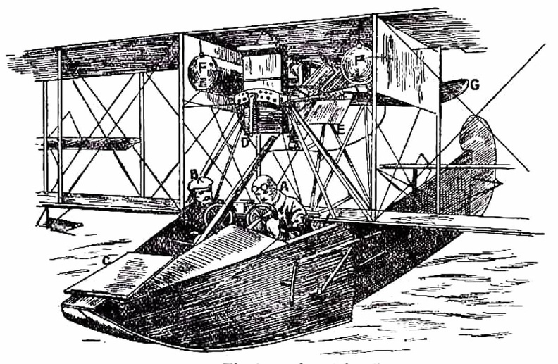
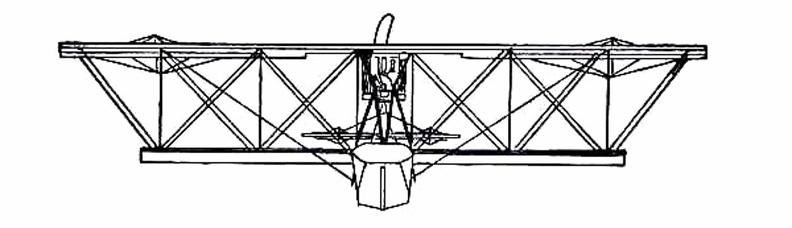
The difficulty with air-cooling—although it had obvious advantages over water-cooling—was to bring enough air to play upon the surfaces of the cylinders; and it was here that the Gnome won so complete a success. In other engines the cylinders were stationary, and their pistons, moving up and down in the cylinders, turned a crank-shaft to the end of which the propeller was fixed. Therefore the only air the cylinders obtained was what rushed upon them through the speed of the machine in flight. But in the Gnome, instead of the cylinders remaining stationary and the crank-shaft revolving, the cylinders themselves spun round, and the crank-shaft did not move. An illustration of this motor with one end of the crank-chamber removed, so that the piston-rods can be seen, is given in the figure. It will be noted that there are seven cylinders, set in the form of a star, and that the seven piston-rods projecting from them come together upon a single crank-pin, which is attached to the stationary crank-shaft and turns round it. The propeller, instead of being fitted to the crank-shaft, as was the case with other motors, was bolted to a plate upon the engine itself, so that when this turned around its crank-shaft, it carried the propeller with it. showing the span of the main-planes, and the curve of the boat-shaped hull.") A Flying Boat
A Flying Boat
showing the span of the main-planes, and the curve of the boat-shaped hull.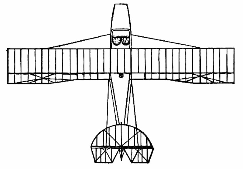
 Ader next turned to steam-driven craft, and built a series of queer, bat-like machines, which he cal...") Ader’s 'Avion'
Ader’s 'Avion'
Ader next turned to steam-driven craft, and built a series of queer, bat-like machines, which he called “Avions,” one of which is illustrated in Fig. 16. Its wings were built up lightly and with great strength by means of hollow wooden spars, and had a span of 54 feet, being deeply arched. The whole machine weighed 1100 lbs., and was thus far smaller and lighter than Maxim’s mighty craft. To propel it, Ader used a couple of horizontal, compound steam engines, which gave 20 h.p. each and drew the machine through the air by means of two 4-bladed screws. The craft was controlled by altering the inclination of its wings, and also by a rudder, the pilot sitting in a carriage below the planes. In 1890, after its inventor had spent a large sum of money, the machine—which, unlike those of Phillips and Maxim, ran upon wheels and was free to rise—did actually make a flight, or rather a leap into the air, covering a distance of about fifty yards. But then, on coming into contact with the ground again, it was wrecked. Ader’s experiments were regarded by the French Government as being so important that he received a grant equalling £20,000 to assist him in continuing his tests; and this goes to show how, even from the first, the French nation was—by reason of its enthusiasm and imagination—able to appreciate what its inventors were striving to attain, and eager to encourage them in their quest. (800 visits) In the development of speed, some remarkable craft are built. Each year there is an international ai...") Racing Deperdussin Monoplane (side view)
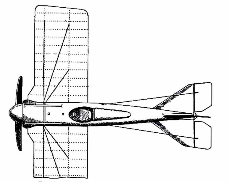
Racing Deperdussin Monoplane (side view)
In the development of speed, some remarkable craft are built. Each year there is an international air race for the possession of the Gordon-Bennett trophy, and to win this designers build special craft. In tiny monoplanes, engines of high power are installed; and the sustaining wings are so reduced, to give a maximum speed, that the machines appear more like projectiles than flying craft. A purely racing-type monoplane is seen in figure.. It represents a Deperdussin, which, with an engine of 160 horse-power, reached a speed of 130 miles an hour. How small this machine was, in relation to its engine-power, will be realised from the fact that the sustaining surface of its wings amounted to only 104 square feet—far less lifting area, in fact, than Lilienthal used in his gliders. Wires and struts are reduced to a minimum; the body is tapered and smoothed. Such a machine, although it carries speed to an extreme, and is in reality a “freak,” teaches useful lessons. But though it provides data for the construction of high-speed scouts, a monoplane of this type would be useless for cross-country flying; and for the reason that it cannot be manœuvred, prior to an ascent, upon anything save the smoothest of ground. Its wings being so small, to ensure a maximum of speed, the machine will not rise until it has run forward a long distance across the ground; and during this run it attains a speed of nearly 90 miles an hour. At such a pace, unless the ground below its wheels was level, it would leap, swerve, and probably overturn. When alighting from a flight, also, again owing to the smallness of its wings, the craft has to plane down so fast that its pilot could not land safely unless he had below him a surface that was absolutely smooth. A. Propeller B. Shield to lessen wind resistance C. Sloping shield which encloses engine (also to minimise wind-pressure). Air passes between the shields B and C to cool the motor. D. Pilot’s seat E. Padded projection against which, when at high speed, the pilot rests his head F. Sustaining-plane Very slightly cambered G. Rudder H. Elevating-plane I. Landing wheels.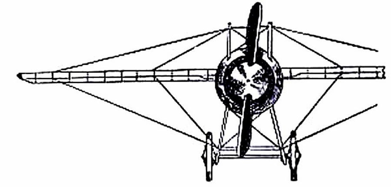
 It was not until 1906, at a time when the Wright aeroplane was capable of long flights, that a real ...") Santos-Dumont’s Biplane which flew at Bagetelle
Santos-Dumont’s Biplane which flew at Bagetelle
It was not until 1906, at a time when the Wright aeroplane was capable of long flights, that a real French success was obtained; and then the flights made were brief, and carried out with a craft that was admittedly crude. It was a biplane of curious construction, built by the Voisin brothers for M. Santos-Dumont—a rich Brazilian who had spent money freely upon airships, and had been occupied, for some time before the Voisins made him this machine, with a craft having propellers to lift it vertically from the ground. Abandoning this idea, he devoted himself to the machine the Voisins built, which is seen in the picture. England, in the building and handling of sea-planes has come well to the fore, and our machines are ...") A Bleriot Sea-plane
A Bleriot Sea-plane
England, in the building and handling of sea-planes has come well to the fore, and our machines are more advanced than those of other countries. The Admiralty has recognised that, acting as a coastal scout in time of war, such craft would be of the utmost value; thus we find air-stations dotted round our seaboard, from which machines may fly in a regular patrol. By the employment of hundreds of craft, operating upon a well-ordered plan, it will be possible in the future to girdle our shores completely; and such machines would not only spy out the approach of an enemy’s fleet, but give battle to hostile aeroplanes or airships which might seek to pass inland. The type of machine we have just described was a biplane, but there are monoplane sea-craft, and a Bleriot fitted for alighting upon the water is shown. The first vacuum balloon was proposed by the Jesuit father, Francis Lana, and described in his book ...") Lana’s proposed vacuum balloon
Lana’s proposed vacuum balloon
The first vacuum balloon was proposed by the Jesuit father, Francis Lana, and described in his book Podromo dell’Arte Maestra Brecia, which appeared in 1670. Though not a practical project like Gusmao’s, it was very ingenious, and marks an interesting phase in the evolution of the fundamental idea of the air ship, or “balloon” as it was called by the inventor, who then coined the word now in common use. Lana proposed to use four copper spheres each 25 feet in diameter and 1/225 inches in wall thickness, quite well exhausted of air, to give ascensional force which he computed at 1,200 pounds aggregate for the four spheres. From these he would suspend the passengers in a boat having a mast and sail to propel the ship in time of favorable wind. Having computed the buoyancy according to well-known physical laws, he could see no possible objection to his project “unless,” he writes, “it be that God would never permit this invention to be practically applied, in order to prevent the consequences that would ensue therefrom in the civil and political government of men.” A.A. Ballast bags filled with sand
B. Instruments (such as a statoscope, which shows at any moment ...") The car of a modern Balloon
The car of a modern Balloon
A.A. Ballast bags filled with sand B. Instruments (such as a statoscope, which shows at any moment whether the balloon is rising or falling; and an altitude meter) C. Ring by which car is attached to balloon. The sea-plane, when a flight is made, is launched upon the water down a slipway; then the pilot and ...") An Avro Sea-Plane
An Avro Sea-Plane
The sea-plane, when a flight is made, is launched upon the water down a slipway; then the pilot and his passenger embark, the motor is started, and the propeller draws the machine across the water at a rapidly increasing pace. The floats raise themselves higher and higher upon the water, as the air-planes exercise a growing lift, until they only just skim the surface. And now comes the moment when the airman, drawing back his elevating lever, seeks to raise his craft from the water into the air. At first only the front of the floats rise, the rear sections clinging to the surface; then, in another instant, the whole float frees itself from the water in a scatter of spray, and the craft glides at a gently-sloping angle into the air. It is the aim of builders, by the curve they impart, to make the floats leave the water with as little resistance as possible. In the floats of the Avro will be noticed a notch, or cut-away section, which occurs at about the centre of the float upon its lower side. This is called a “step,” and is to help the float to lift from the water. When the main-planes draw upward, as the craft moves prior to its flight, the floats tend, as has been said, to raise themselves in the water; and as they do so, lifting first towards the bow, there comes a space between the upward-cut “step” and the surface of the water. Into this space air finds its way and, by helping still further to free the float from the surface, aids greatly at the moment when the pilot—operating his hand-lever—seeks the final lift which will carry him aloft. A. Propeller B. 100-h.p. Gnome motor, hidden by shield C. Main-planes D. Observer’s seat E. Pilot’s seat F. Rudder G. Elevating-plane H. Float to support tail I. Main floats to bear the weight of the machine. “Looping the loop,” which has made so great a sensation, has taught airmen one definite lesson; ...") Looping the loop
Looping the loop
“Looping the loop,” which has made so great a sensation, has taught airmen one definite lesson; and it is this: no matter how their machines may be beaten and tossed by the wind, they need not fear a fall—provided they are high enough above ground. The movements of a machine, as it makes a series of “loops,” are shown in the figure. The pilot reaches a high speed before he rears up his machine to begin the “loop,” and this downward velocity is attained by diving; then, when he estimates his pace sufficient, he pulls his elevating-lever back and the machine leaps upward, rearing itself vertically towards the sky, turning over on its back, then diving again and coming right-side-up—thus achieving a complete somersault. A skilled trick-flyer, also, will allow his machine to drop sideways or tail first, deliberately working the controls so that it shall do so. Then, just as it seems to spectators that he is falling to destruction, he will dive or twist, regain the mastery of his machine, and descend in a normal glide. An Airship leaving its shed
A. The machine emerging stern first
B. A sister craft in dock
C. Th...") An Airship leaving its shed
An Airship leaving its shed
An Airship leaving its shed A. The machine emerging stern first B. A sister craft in dock C. The launching crews D. Rails upon which the cars of the airship move, so as to prevent its swinging sideways in a gust E. Outlook station upon the roof of the shed F. Workshops; living quarters for the crews; plant for making hydrogen gas. after testing more than 200 wing designs and plane surfaces in their wind tunnel, the Wright Brother...") The Four forces of flight
The Four forces of flight
after testing more than 200 wing designs and plane surfaces in their wind tunnel, the Wright Brothers found out how to figure correctly the amount of curve, or camber, that was essential to weight-carrying wings. They discovered, too, that before man could be flown through the air, he must have his wings attached firmly to a body or platform which was firm and controllable. The Wrights in their earliest experiments had realized that to be practical their machine must be built not only to fly in a straight line, but also in order that it could be steered to the right or to the left. One day, Orville was twisting a cardboard box in his hand when Wilbur noticed it. Immediately he saw the solution to the problem of steering their airplane. The result was a design which changed the lift of either end of the wing by warping its surface. If one end of the wing was warped to give it more lift, the machine would lift on that side and fall off into a turn. Thus the problem of steering was solved by the Wrights A. Hull
B. seats for crew
C. Planes
D. Motor
E. Propeller
F. Rudder
G. Elevators.
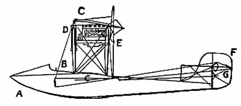
...") A Flying Boat - side view
A Flying Boat - side view
A. Hull B. seats for crew C. Planes D. Motor E. Propeller F. Rudder G. Elevators.
 An experimenter who braved this apathy and won his way until he became a constructor of aircraft, wa...") The Roe Triplane
The Roe Triplane
An experimenter who braved this apathy and won his way until he became a constructor of aircraft, was Mr. A. V. Roe. For some time he was an advocate of the triplane form of machine—a craft, that is to say, with three main-planes fitted one above another. The machine with which he obtained flights, although they were very brief, is seen in the figure. Subsequently, however, Mr. Roe adopted the biplane form. His distinction in the pioneer days was that he managed to make his triplane lift into the air and fly a short distance, with the aid of a motor-cycle engine developing no more than 9 h.p. A.A.A. Three main-planes B. Motor C. Four-bladed propeller D.D.D. Triplane tail E. Rudder F. Landing gear. The driver of a modern-type aeroplane, sitting snugly within its hull, has a wheel and instrument-bo...") The Control of a Biplane
The Control of a Biplane
The driver of a modern-type aeroplane, sitting snugly within its hull, has a wheel and instrument-board before him, as sketched. As he flies across country he has many things to think of. Holding the control-wheel in both hands, his feet resting upon the rudder-bar, his eyes rove constantly among the instruments [Pg 163]on the dashboard before him. He glances at the compass often, for it is by this that he steers; and when the air is clear, and the earth below plainly seen, he will every now and then glance over the side of the hull, so as to be on the look-out for a landmark that may tell him he is on his course. A. Pilot’s seat B. Hand-wheel (pushed forward or backward operates elevator; twisted sideways works ailerons) C. Foot-bar actuating rudder D. Compass E. Dial showing number of revolutions per minute that engine is making F. Gauge showing pressure in petrol tank G. Speed indicator H. Dial showing altitude I. Clock J. Switch for cutting off ignition. A. Wheels operating elevating-planes and rudder
B. Height recorder
C. Speaking-tube to communicate...") Control platform of an Airship
Control platform of an Airship
A. Wheels operating elevating-planes and rudder B. Height recorder C. Speaking-tube to communicate with engineers. A machine that has achieved success, owing to its power of varying speed, is the Sopwith military bi...") Sopwith Military Biplane
Sopwith Military Biplane
A machine that has achieved success, owing to its power of varying speed, is the Sopwith military biplane. Adopting a practice that has become general, its wings are fitted upon what is practically a monoplane body. Tail-planes and rudder are the same as in a monoplane. The top main-plane, as will be seen, is set slightly in advance of the lower. The system is called “staggering”; and the idea is that, by placing the upper plane ahead of the lower, the total lifting power will be increased. It has been proved a disadvantage of the biplane that, when the main-planes are placed one above another, there is a slight loss of lift owing to the fact that, acting upon the air as they do quite close to each other, a certain amount of interference occurs between them—one tending to disturb the air-stream in which the other moves. By “staggering” the two planes this interference is overcome; but some makers regard it as a small consideration, and build their planes in the ordinary way, allowing as large a gap as possible between them. In the Sopwith military machine, engine and propeller are in front of the main-planes; then come the places for pilot and observer. The pilot sits first, and the body of the machine is so high that only his head appears above it, while just in front of his face, to deflect the wind-rush from the propeller, there is a raised section of the hull which acts as a screen. Behind the pilot, sitting in a second opening in the hull, is the observer. He has a view forward, rendered the better by setting back the lower-plane; while at the point at which it joins the body of the machine, immediately below him, this plane is hollowed out, so that he can look directly upon the earth below. Small windows are also fitted upon either side of the hull. Through those in front the pilot may glance when descending from a flight, so as to judge his distance from the ground, while the others are utilised by the observer, as he turns to look from side to side. This biplane, and many others, is balanced against sideway roll by ailerons, and not by warping the wings. Constant warping, such as is necessary in the everyday use of machines, has been declared to strain a plane and render it weak; therefore the use of ailerons is now favoured. A. Propeller B. Motor, partly hidden by shield C.C. Main-planes D. Pilot’s seat E. Observer’s seat F. Outlook windows in side of hull G. Rudder H. Elevating-plane I. Landing gear. A typical craft, representing the first of those navigated with any certainty, is shown in Figure. A...") Early-type Airship
Early-type Airship
A typical craft, representing the first of those navigated with any certainty, is shown in Figure. A gas-containing envelope, made of a light, strong, varnished fabric, is kept taut by the pressure of the gas within; the car, constructed of wood or metal tubing, is suspended by ropes from the envelope, and contains engine and crew, with a two-bladed propeller revolving astern. Such a machine, in its control, had an elevating-plane and rudder, upon the same principle as those of the aeroplane. One of the difficulties to be overcome was the expansion and contraction of gas in the envelope owing to differences in altitude and temperature. When the craft ascended, its envelope completely inflated, the gas began to dilate owing to the outer air becoming less dense; and some had to be allowed to escape through automatic valves. Then, should the machine descend to a lower level, there was not sufficient gas in the envelope to keep it tightly stretched, and it tended to sag at the bow as it was driven through the air. A. Gas envelope B. Car suspended below envelope C. Motor, which drives propeller (D) through a shaft E. Small horizontal plane for rising or descending F. Fixed fin, or keel plane, to give stability G. Rudder. By another method, shown in figure, the sea-plane is launched from a cable suspended between two mas...") Launching a sea-plane from a wire
Launching a sea-plane from a wire
By another method, shown in figure, the sea-plane is launched from a cable suspended between two masts, and can come to rest upon the cable again after a flight has been made. The machine is hung upon the cable prior to making an ascent; then the pilot starts his engine, and as his machine glides forward along the cable he releases a catch and soars into the air. Upon returning he flies beneath the cable, and makes his craft rise until the “V”-shaped apparatus above his head is caught by the cable and the catch becomes operative; then he stops his motor, and his craft hangs from the cable as it did before. A. Sea-plane B. Cable C. The “V”-shaped apparatus which guides the cable into the clip (D.) and so suspends the machine from the wire. Out in Dayton, Ohio, there were two small brothers, who dreamed, as countless other children before ...") Wright Brothers' Bicycle shop
Wright Brothers' Bicycle shop
Out in Dayton, Ohio, there were two small brothers, who dreamed, as countless other children before them had dreamed, of flying like birds through the air. Their dreams were heightened by a small toy given to them by their father, the pastor of a local church. This toy was to lead to an idea which had a profound effect on the world. You would probably call it a flying propeller. It consisted of a wooden propeller which slipped over a notched stick. By placing a finger against the propeller and rapidly pushing it up the notched stick, the propeller was made to whirl up off the end of the stick and fly into the air. The brothers, young as they were, never quite forgot this little toy as they continued to dream of flying like birds through the air. Though the brothers continued to dream of flying, they were not the kind of lads who spent all their time in dreaming. They made kites which flew a little better and a little higher than those made by the other boys in the neighborhood. They built a press to print their own little newspaper, and they dabbled in woodcuts. To carve out porch posts for their father’s home they built an eight-foot wood-turning lathe. Indeed, they were the sort of boys who caused the neighbors to say, “What will they think of next?” The brothers knew that if they ever wanted to see their dreams come true they must earn their own capital. In the early nineties America was in the midst of the bicycle craze. Everyone who could possibly afford to do so owned a bicycle of some sort and belonged to a cycle club. Being mechanically minded, the brothers did the logical thing. They set themselves up in a small bicycle shop in Dayton, next door to their home. The bicycle shop in Dayton prospered, for the brothers were careful and expert mechanics, and cyclists in need of repairs made their way to the Wright Brothers’ shop. Parseval Kite Balloon.
Another valiant English leader in aërostation was James Glaisher, member ...") Glaisher and Coxwell
Glaisher and Coxwell
Parseval Kite Balloon. Another valiant English leader in aërostation was James Glaisher, member of the British Association for the Advancement of Science. As one of a committee of twelve appointed by that body in 1861, to explore the higher strata of the atmosphere by means of the balloon, he volunteered his services as an observer, when no other capable man could offer to do so. With a professional aëronaut, Mr. Coxwell, and a new balloon specially constructed for the work, cubing 90,000 feet, he made eleven ascensions for the society, four from Wolverhampton, seven from Woolwich. Incidentally he made seventeen other ascents of various altitude; not at the expense of the committee, but as a scientific passenger in public balloon ascents advertised beforehand. The Wright Brothers were not only inspired mechanics (as many people still believe today) but seriou...") Wright Brotherrs wind tunnel
Wright Brotherrs wind tunnel
The Wright Brothers were not only inspired mechanics (as many people still believe today) but serious scientists, working along the soundest lines. In their keen desire to know what air pressure on wings really was, they cleared a corner of their bicycle shop and built a small wind tunnel with spare lumber and an old electric fan. They built small wing sections of various shapes and experimented with them in their wind tunnel. The electric fan was used to create the moving air around the wing section. By attaching the wing sections to a supporting frame and connecting the frame with a pointer and dial, they were able to keep a record of the effect of moving air on each experimental wing section. Through their wind tunnel research the Wright Brothers discovered the four forces that control all heavier-than-air flight: lift, thrust, weight, and drag. The Curtiss Biplane in flight") The Curtiss Biplane in flight
The Curtiss Biplane in flight
The Curtiss Biplane in flight Hull of a Zeppelin during construction.
Craft of the semi-rigid type provide a link between small...") Hull of a Zeppelin during construction
Hull of a Zeppelin during construction
Hull of a Zeppelin during construction. Craft of the semi-rigid type provide a link between small, non-rigid ships and the very large machine which is built with an entirely rigid framework, and has its example in the Zeppelin. The maker forms a skeleton hull of aluminium or some light metal alloy, a method that is shown in figure. The hull of a Zeppelin, slightly more than 500 feet in length, is sheathed with tightly stretched fabric; and within it are the gas-containers—a row of seventeen separate balloons, each in a compartment by itself, and containing a total of nearly 1,000,000 cubic feet of gas—which give these airships a lifting power of close upon 30 tons. showing the span of main-planes, elevator, and tail, also the positions of landing gear and pilot’...") The Farman Biplane - top view
The Farman Biplane - top view
showing the span of main-planes, elevator, and tail, also the positions of landing gear and pilot’s seat. The ripping panel, invented in 1844 by America’s foremost pioneer aëronaut, John Wise, is a simpl...") Diagram of a modern spherical balloon with ripping panel
Diagram of a modern spherical balloon with ripping panel
The ripping panel, invented in 1844 by America’s foremost pioneer aëronaut, John Wise, is a simple and an excellent practical device. This is a long patch running longitudinally above the equator[8] of the balloon, feebly sewed to the envelope, and having a cord, called the “ripping cord,” extending down to the car along the outside or inside of the bag, so that the pilot on coming to earth can let out the gas quickly by tearing a rent in the balloon, thus flattening it promptly on the earth’s surface, so as to avoid dragging and bumping if any wind prevails. The Curtiss Biplane making a turn") The Curtiss Biplane making a turn
The Curtiss Biplane making a turn
The Curtiss Biplane making a turn In the Hall of the Gods, in the Egyptian Museum, there is a small bronze plaque of great antiquity, ...") Egyptian bronze representing a flying man
Egyptian bronze representing a flying man
In the Hall of the Gods, in the Egyptian Museum, there is a small bronze plaque of great antiquity, where we see in relief a man flying the two extended wings. It is true that we agree to consider this piece as a symbolic composition rather than as the representation of an aircraft. Historians have unearthed stories in cuneiform writing of man’s attempts to fly. Some of these ins...") The flight of Etana
The flight of Etana
Historians have unearthed stories in cuneiform writing of man’s attempts to fly. Some of these inscriptions date back more than five thousand years, to 3500 B.C. Perhaps the most famous of these stories is the ancient Babylonian tale of the shepherd boy, Etana, who rode on the back of an eagle. Put together scientifically and from sections of wood specially tested, a remarkable strength may be...") Testing the girder-built body of an aircraft
Testing the girder-built body of an aircraft
Put together scientifically and from sections of wood specially tested, a remarkable strength may be obtained by such a method of building. The figure shows how a girder aircraft body, supported by trestles only at its ends, may support from its centre, without yielding, a tray containing a number of heavy weights Air-racing, as made popular by the proprietors of the Hendon aerodrome, forms so fascinating a sight...") A pylon, or mark-tower, on the flying track
A pylon, or mark-tower, on the flying track
Air-racing, as made popular by the proprietors of the Hendon aerodrome, forms so fascinating a sight that, on a day of public holiday, as many as 50,000 people will assemble in the enclosures. To stand near one of the pylons—wooden towers which mark the turning-points of the course—and see the air-racers come rushing by, is to gain such an impression of speed as almost makes the watcher hold his breath. The pilot in a flying race has one chief aim: to fly the shortest way. Every fraction of a second is of importance; and if he can circle the pylons more skilfully than his rivals, he may win the race, even though his machine—in its actual speed—may be no faster than theirs. showing the position of the body and the construction of the landing gear.") Grahame-White Military Biplane - front view
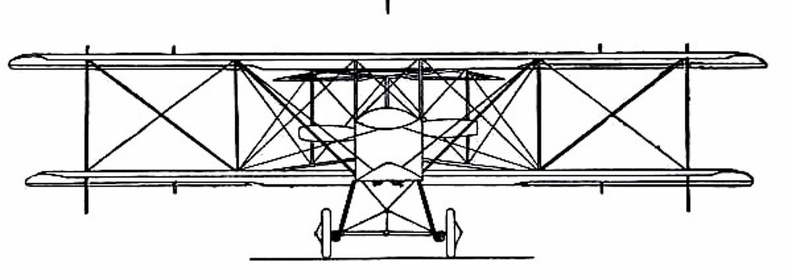
Grahame-White Military Biplane - front view
showing the position of the body and the construction of the landing gear.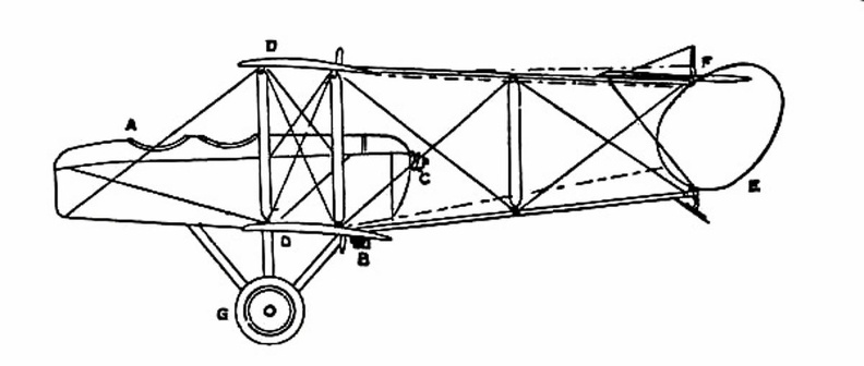
 showing the chassis and the position between the planes of the two ailerons (A.A.).") The Curtiss Biplane front view
The Curtiss Biplane front view
showing the chassis and the position between the planes of the two ailerons (A.A.). showing shape and spread of planes and tail, and position of pilot and passenger.") Grahame-White Military Biplane
Grahame-White Military Biplane
showing shape and spread of planes and tail, and position of pilot and passenger.
 A more reasonable plan for practical navigation was devised and tried by the Robert brothers. A melo...") Robert Brothers’ dirigible, 1784
Robert Brothers’ dirigible, 1784
A more reasonable plan for practical navigation was devised and tried by the Robert brothers. A melon-shaped balloon, fifty-two feet long by thirty-two feet in diameter, was made of silk and inflated with pure hydrogen. Beneath was suspended a longish car of light wood covered with sky-blue silk. This elegant ship was to be rowed through heaven by means of six silken oars actuated by sturdy sailors. A silken rudder should guide her at pleasure when the winds were asleep, or softly playing in the placid sky. She was a fairy bark, indeed, a soaring castle lovely to behold. After a preliminary trial, accompanied by their patron, the Duke de Chartres, they were ready for a substantial journey. On September 19, 1784, the vessel was inflated and taken to the Garden of the Tuileries, in front of the palace, where its cords were held by Marshall Richelieu and three other noblemen. At eleven forty-five the two Roberts and their brother-in-law arose and drifted beyond the horizon on a seven hours’ cruise. Before coming to earth, they plied the oars vigorously, and described a curve of one kilometer radius, thus deviating 22° from the feeble wind then prevailing. Coal-gas superseded hot air in the filling of balloons, the latter being unsatisfactory, seeing that...") A modern Balloon
A modern Balloon
Coal-gas superseded hot air in the filling of balloons, the latter being unsatisfactory, seeing that it cooled rapidly and allowed the balloon to descend; the only alternative being to do what some of the first aeronauts did, and burn a fire below the neck of their balloon even when in the air. But the dangers of this were great, seeing that the whole envelope might easily become ignited. With balloons filled with coal-gas long flights were possible, but they had always this disadvantage—the voyagers were at the mercy of the wind, and could not fly in any direction they might choose. If the wind blew from the north then they were driven south, the balloon being a bubble in the air, wafted by every gust. Aeronauts became disgusted with this inability to guide the flight of a balloon, and many quaint controls were tested; such, for example, as the use of a large pair of oars with which the balloonist, sitting in the car of his craft, rowed vigorously in the air.
In July, at Rheims, there was to be the great flying meeting; and Farman had made up his mind to...") The Farman Biplane
The Farman Biplane
In July, at Rheims, there was to be the great flying meeting; and Farman had made up his mind to wait for this. Aided by the experience he had gained with the Voisin machine, he had designed a craft which should be generally more efficient and faster in flight, and more quickly responsive to its controls. The biplane he produced, marking as it did a step forward in construction, is a machine that needs description. The general appearance of the craft is indicated by Fig. 46, while an illustration of this type of machine in flight will be found on Plate VII. A feature of the Voisin that Farman discarded was the vertical panel fitted between the main-planes to give sideway stability. An objection to these planes was that they added to the weight of the machine and checked its speed, tending also to drive it from its course should there be a side wind. But in taking away such fixed balancing-planes, Farman had to substitute another device; and what he did was to work upon the same theory as the Wrights had done, and obtain a similar result in a different way. They, it will be remembered, had warped the rear portions of their main-planes. Farman kept his planes rigid, but fitted to their rear extremities four narrow, hinged planes, or flaps, which could be moved up and down and were called ailerons. Their effect was the same as with the Wright wing-warp. When a gust tilted the machine, the pilot drew down the ailerons upon the side that was inclined downward; whereupon the air-pressure, acting upon the drawn-down surfaces, restored the machine to an even keel. A. Elevating-plane; B.B. Main-planes; C. Pilot’s seat; D. Motor and propeller; E. Petrol tank; F.F. Hinged balancing-planes, or ailerons; G.G. Tail-planes; H.H. Twin vertical rudders; I. Landing wheels and skid One of the earliest authenticated devices of this kind was the invention of Blanchard, described by ...") Blanchard’s flying-machine
Blanchard’s flying-machine
One of the earliest authenticated devices of this kind was the invention of Blanchard, described by him in the Journal de Paris, August 28, 1781, nearly two years before the invention of the hot-air balloon, of which he became later an enthusiastic votary. As his device is but one of a large number that appeared before the close of the nineteenth century, and the advent of light motors, the reader who wishes fuller acquaintance with man-driven airships may be referred to Mr. Chanute’s book, entitled Progress in Flying-Machines, which describes a large variety of such inventions, and discusses the merit and weakness of each. The Voisin Biplane - top view") The Voisin Biplane - top view
The Voisin Biplane - top view
The Voisin Biplane - top view They found that a slight curve or camber in the wing section would cause the moving air to travel fa...") Wright Brothers' Wind tunnel
Wright Brothers' Wind tunnel
They found that a slight curve or camber in the wing section would cause the moving air to travel farther over the top of the wing surface than along the under side. This made the air pressure greater under the wing, gave a suction effect above the wing, and caused it to rise, creating lift. They discovered that a wing section of the proper camber would counteract the weight of gravity. Thus, a wing must be so designed that, with a certain amount of air flowing around it, it would lift a certain weight. They also discovered that air flow against any surface attached to the wing would cause a resistance or drag. Hundreds of experiments in their wind tunnel with various types of wing shapes gave the Wrights a series of tables from which to design a wing that would create the lift for a designed weight. (1272 visits) We reproduce as a curiosity this charming vignette, where we see the inventor Scintilla driving his ...") Electric flying machine depicted in Le Philosophe sans pretension (1775)
Electric flying machine depicted in Le Philosophe sans pretension (1775)
We reproduce as a curiosity this charming vignette, where we see the inventor Scintilla driving his machine. showing the spread of the planes and tail, and the delicate taper of the long, canoe-shaped body.") The Antoinette Monoplane - top view
The Antoinette Monoplane - top view
showing the spread of the planes and tail, and the delicate taper of the long, canoe-shaped body. The story of Dædalus and Icarus also tells us that man believed flying was somehow possible. Dædal...") Daedalus and Icarus
Daedalus and Icarus
The story of Dædalus and Icarus also tells us that man believed flying was somehow possible. Dædalus was a very clever man who lived with his son Icarus on the Island of Crete. The king of this island requested Dædalus to build a labyrinth or maze for him. Dædalus constructed the labyrinth so cleverly that only the king, who had the clue to the winding passages, could find his way out. One day the king became very angry at Dædalus and threw both him and his son Icarus into the labyrinth, intending that they should perish. Dædalus, who had been dreaming of flying, fashioned wings from wax and feathers, with which he and Icarus could fly to freedom. He cautioned Icarus that he must not fly too high or the sun would melt the wax in his wings. Icarus, impatient to escape, scarcely listened. Like birds the two flew into the air, quickly leaving the walls of the labyrinth. Dædalus, flying low, safely crossed the sea and reached Sicily. Icarus, unfortunately, failed to heed his father’s warning. Flying was so much fun that he rose higher and higher. Suddenly feathers began to drop one by one. Too late Icarus realized that the sun had melted the wax in his wings. Down, down he fell into the sea. By 1903 the Wright Brothers were ready to build a powered man-carrying flying machine. Their experim...") Wright Brothers first powered airplane
Wright Brothers first powered airplane
By 1903 the Wright Brothers were ready to build a powered man-carrying flying machine. Their experiments had shown them just how much moving air was necessary to create lift in such a machine. To create the needed thrust, an engine having eight horsepower and weighing not over 200 pounds had to be fitted into the machine. Such an engine was not available, so the Wrights built one in their shop at Dayton, Ohio. They were ready to ship their airplane to Kitty Hawk, N. C., in the fall of 1903. At the beginning of 1909 there were two types of successful aeroplane—the Wright and the Voisin. B...") The Voisin Biplane
The Voisin Biplane
At the beginning of 1909 there were two types of successful aeroplane—the Wright and the Voisin. Bleriot had flown with his monoplane and flown well; but he was still in the process of evolving a practical machine, and several other inventors were in a similar stage. It was the Wright and the Voisin which had proved their worth; and the Wright, as has been said, was the better of the two. Of the Voisin, as flown in 1909, a reproduction is given in the figure. It was a heavier aeroplane than the Wrights’, owing largely to the weight of its alighting gear (250 lbs.) and of its big balancing tail (more than 100 lbs.); hence the necessity for using a 50-h.p. motor, which drove a two-bladed metal propeller at the rate of 1200 revolutions a minute. The Voisin brothers, and other French makers, did not approve of the two-propeller system of the Wrights: they preferred one screw, revolving at high speed. But there was no doubt—at any rate in this stage of aviation—that the Wright method was more efficient than that of the Frenchmen. It was calculated, indeed, that the Wright biplane, when actually in the air, could be driven at an expenditure of only 15 h.p.; whereas the Voisin, even with its 50-h.p. motor running at full speed, had only just enough power to fly. A. Elevating plane B. Pilot’s seat C.C. Main-planes D. Engine and propeller E. Landing chassis F. Balancing tail G. Rudder. Reproduction by heliogravure of the figure from the Journal des sçavans (1678).
Extract from a l...") Besnier's flying apparatus
Besnier's flying apparatus
Reproduction by heliogravure of the figure from the Journal des sçavans (1678). Extract from a letter written to Mr. Toynard on a Machine of a new invention to fly in the air. A, right front aisle. — B, left rear aisle. — C, left front aisle. — D, right rear aisle. — E, fissure of the left foot which lowers the D aisle, when the left hand lowers the Aisle C. — F, fissure of the right foot which lowers the D-pin when the left hand lowers the C-pin. (1358 visits) Certainly Lana's project is impracticable: the learned Jesuit did not foresee that his empty copper ...") Father Lana's aerial ship (1670)
Father Lana's aerial ship (1670)
Certainly Lana's project is impracticable: the learned Jesuit did not foresee that his empty copper balloons would be crushed by the external atmospheric pressure; but he nevertheless had a very clear idea and very remarkable for his time of the principle of aerial navigation by balloons lighter than the volume of air which they move. He ends his long chapter with some very curious considerations: I do not see any other difficulties that can be opposed to this idea, except one which seems to me more important than all the others, and that God will not allow this invention to be ever successfully applied in practice, in order to prevent the consequences which would result from it for the civil and political government of men. Indeed, who does not see that there is no State which would be insured against a stroke of surprise, because this ship would be heading in a straight line on one of its strongholds, and, landing there, could descend there soldiers., after an engraving of the time (1359 visits) The attached engraving is the exact reproduction of the parachute that the author also defines in th...") The Venice parachute (1617), after an engraving of the time
The Venice parachute (1617), after an engraving of the time
The attached engraving is the exact reproduction of the parachute that the author also defines in the following terms, certainly inspired by those of Leonardo da Vinci: With a square veil stretched out with four equal poles and having tied four ropes to the four quinces, a man without danger will be able to throw himself from the top of a tower or some other prominent place; because although, at the hour, there is no wind, the effort of he who falls will bring wind which will hold back the sail, lest it fall violently, but gradually descend. The man therefore must measure himself with the size of the sail. After a year of exhaustive study and experiments with models in their wind tunnel, the Wright Brothe...") The Wright Brothers experimental glider
The Wright Brothers experimental glider
After a year of exhaustive study and experiments with models in their wind tunnel, the Wright Brothers were ready to experiment with a man-carrying glider. With the thoroughness that was typical of every move of the Wrights, the brothers asked the government to let them have information on meteorological conditions all over the country. By studying the weather charts they were able to find a locality where there was a continual flow of wind. This would be nature’s wind tunnel where they could test their glider day after day. Through their study of the charts they found that the wind conditions at Kitty Hawk, on the North Carolina coast, seemed to offer the best possibilities for their glider test. Orville and Wilbur Wright began their experiments with a small man-carrying glider at Kitty Hawk in 1900. From that time until 1903 they made hundreds of successful glider flights and kept accurate records of each flight. They recorded wind velocity, angle of flight, duration of flight, time of day, temperature, humidity, and sky conditions overhead with the typical Wright attention to detail. Each year the Wrights constructed new gliders which embodied principles they had discovered for themselves during their flights at Kitty Hawk. Each glider was larger and had longer and narrower wings than the one before. During the fall of 1902 the brothers recorded nearly a thousand flights in a glider with a wingspan of thirty-two feet. It had a front elevator and a vertical tail which helped to maintain lateral stability. To meet the demand for a purely scouting machine, in which pilot and passenger shall have a clear fi...") Scouting Monoplane, with occupants below the wings.
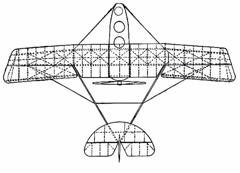
Scouting Monoplane, with occupants below the wings.
To meet the demand for a purely scouting machine, in which pilot and passenger shall have a clear field for observation, both above and below, a monoplane has been designed which is called the “parasol.” This machine, a Morane-Saulnier, is shown. The two sustaining wings, forming a single surface, are raised above the body so that its occupants have nothing to impede their view earthward; and they can also see above them—an advantage of course in time of war, seeing that an enemy might be hovering overhead A. Engine and propeller B. Plane raised above hull C. Seats for pilot and passenger D. Rudder E. Elevating-plane. Of famous aeroplanes at Rheims, five types stood out by themselves—the Farman, the Voisin, the Wri...") The Curtiss Biplane
The Curtiss Biplane
Of famous aeroplanes at Rheims, five types stood out by themselves—the Farman, the Voisin, the Wright, the Bleriot, and the Antoinette, all of which have been described. But there was one other, which few people had heard of before it appeared here. This was the Curtiss biplane, built by an American named Glenn H. Curtiss, and engined with a motor which also bore his name. Curtiss had experimented with many power-driven machines—motor-cycles, motor-cars, airships, and aeroplanes—and had won a prize in America with a small, light biplane, and it was a craft of this type—as seen in the figure —that he brought with him to Rheims, his idea being to compete for the speed prize. The machine had a front elevator and tail-planes, according to the practice in biplane construction; but an innovation was the setting of the ailerons midway between the main-planes—a position that will be noted in the sketch; another novelty was the way these ailerons operated. At the pilot’s back, as he sat in his driving seat, was an upright rod with two shoulder-pieces—by means of which, should he shift his body, he could swing the rod from side to side. Wires ran from the rod to the ailerons; and if the pilot leaned over, say, to the right, he drew down the ailerons on the left side of the machine. The merit of such a control was that it was instinctive; that is to say, should the biplane tip down on one side, it was natural for the pilot to lean away from the plane-ends that were sinking; and he operated the ailerons automatically, as he did this, and so brought the machine level again. A. Elevating-planes B. Pilot’s seat and control-wheel C.C. Main-planes D. Ailerons E. Motor and propeller F. Tail-plane and rudder. A. Lower part of aeroplane’s hull
B. Revolving barrel to which bombs are clipped
C. Bombs
D. Re...") Bomb-releasing mechanism
Bomb-releasing mechanism
A. Lower part of aeroplane’s hull B. Revolving barrel to which bombs are clipped C. Bombs D. Releasing mechanism operated by marksman in machine. Bombs may be carried and dropped when opportunity offers; and as an improvement upon the early method, which was simply to throw these from the machine, there are releasing mechanisms now devised which carry a number of projectiles and drop them one by one as a lever is moved. The bombs, which are long, pointed, and balanced so that they will fall head first, are clipped round a barrel rather like that of a revolver, which is fixed beneath the aeroplane’s hull just below the occupants’ seat. Mechanism causes the carrying chamber to revolve and bring each bomb against a releasing catch, which—at a movement of the marksman’s lever—throws it outwards and downward. In 1678, Besnier, a French locksmith, constructed a curious flying machine consisting of two wooden ...") Besnier and his wings
Besnier and his wings
In 1678, Besnier, a French locksmith, constructed a curious flying machine consisting of two wooden bars which rested on his shoulders. At the ends of the bars he attached muslin wings, arranged to open on the down stroke and close on the up stroke. The wings were operated by moving the arms and legs. Although Besnier failed to realize that no man had sufficient muscular strength to fly as the bird flies, he did sense part of the truth—that gliding with the air currents was possible. During his experiments he is said to have jumped from a window sill, glided over the roof of a near-by cottage, and landed on a barge in the river. The Bleriot Monoplane - top view showing its bird-like shape and the position of the pilot.") The Bleriot Monoplane - top view
The Bleriot Monoplane - top view
The Bleriot Monoplane - top view showing its bird-like shape and the position of the pilot. he vessel selected for that famous cruise was The Great Balloon of Nassau, then recently built by Mr...") The Great Balloon of Nassau
The Great Balloon of Nassau
he vessel selected for that famous cruise was The Great Balloon of Nassau, then recently built by Mr. Green and representing all that his skill and experience could devise. It was of pear shape, formed of the finest crimson and white silk, “spun, wove and dyed expressly for the purpose,” and comprising when distended a volume of 85,000 cubic feet. From its stout balloon-ring six feet in diameter was suspended a wicker car measuring nine feet long by four wide, having a seat across either end, and a cushioned bottom to serve as a bed, if such should be needed. Across the middle of the car was a plank supporting a windlass for raising or lowering the guide-rope, that is a heavy rope which could be trailed over land, or water, to keep the balloon at a nearly constant level without expenditure of ballast, and to check its speed on landing. This valuable device invented by Mr. Green in 1820, was now to receive adequate trial, which, indeed, formed one of the chief purposes of the cruise. Other paraphernalia of the voyage were food and drink, warm clothing, lamps, trumpets, telescopes, barometers, a quicklime coffee-heater, a grapnel and cable, and a ton of sand ballast in bags. A coastal sea-plane, as now planned, is a craft having, say, two engines, each devolving 120 h.p., w...") Sea-plane to carry a crew of seven
Sea-plane to carry a crew of seven
A coastal sea-plane, as now planned, is a craft having, say, two engines, each devolving 120 h.p., with a wing span of some 80 feet, and an accommodation in its hull for three men—the pilot, a combatant with a machine-gun, and an observer with an installation of wireless. But types are changing constantly, and the tendency is to build larger craft. A machine weighing a couple of tons is shown, and a novelty in regard to it is that it has wheels upon either side of its boat-shaped car, upon which it can move on land, and which fold upward when it rests upon the water. A. Hull upon which the machine floats when in the sea B.B.B. Wheels upon which it may move when on land, and which fold upward when it is on the water C. Pilot’s controlling wheel D.D. Main sustaining planes E. Four-bladed propeller driven by chain-gearing from engine within the hull. The examination of the original drawings of the great Italian artist is intersting. We reproduce by ...") Facsimile of Leonardo da Vinci's drawings on artificial wings
Facsimile of Leonardo da Vinci's drawings on artificial wings
The examination of the original drawings of the great Italian artist is intersting. We reproduce by heliogravure a complete plate; it makes it possible to follow the thought which presided over its execution. We let Dr. Hureau de Villeneuve interpret it. We see in the second row on the right a small character quite similar to a demon or a genie, for he wears a flame on his head and, next to this flame, a Latin cross. His arms end with the fingers of a bat. The figure is not yet finished when Leonardo already recognizes its insufficiency and, guessing the little muscular action of the arms, thinks of using the force of the legs. So we see a little higher, in the same plank, a vigorous man placed on his stomach, his legs bent and about to launch a violent kick. The protruding muscles, traced by an anatomist's pencil, reveal the great painter in an unassuming drawing. Leonardo da Vinci, the great Italian artist and scientist, who lived in the fifteenth century, spent...") Leonardo da Vinci's Glider and Parachute Idea
Leonardo da Vinci's Glider and Parachute Idea
Leonardo da Vinci, the great Italian artist and scientist, who lived in the fifteenth century, spent years experimenting with the idea of flying. He made a number of sketches of wings to be fitted to the arms and legs of man. His plan for a parachute was soundly worked out and his idea that the wings of a flying machine should be patterned after the wings of the bat found expression in the doped fabric covering of our early airplanes.