


 Lady") Lady
Lady
Lady Young woman") Young woman
Young woman
Young woman Lady in scarf and hat") Lady in scarf and hat
Lady in scarf and hat
Lady in scarf and hat Air-racing, as made popular by the proprietors of the Hendon aerodrome, forms so fascinating a sight...") A pylon, or mark-tower, on the flying track
A pylon, or mark-tower, on the flying track
Air-racing, as made popular by the proprietors of the Hendon aerodrome, forms so fascinating a sight that, on a day of public holiday, as many as 50,000 people will assemble in the enclosures. To stand near one of the pylons—wooden towers which mark the turning-points of the course—and see the air-racers come rushing by, is to gain such an impression of speed as almost makes the watcher hold his breath. The pilot in a flying race has one chief aim: to fly the shortest way. Every fraction of a second is of importance; and if he can circle the pylons more skilfully than his rivals, he may win the race, even though his machine—in its actual speed—may be no faster than theirs. Airships, like aeroplanes, are being armed with guns and bombs; and their power of raising weights e...") Aeroplanes attacking an airship from above
Aeroplanes attacking an airship from above
Airships, like aeroplanes, are being armed with guns and bombs; and their power of raising weights enables them to carry heavy weapons. Large and highly destructive bombs have been tested in the German airships, being released over the sea and aimed at targets in the form of rafts. Latest-type airships also carry guns in their cars; and the Zeppelins have a platform upon the tops of their hulls, reached by a ladder through the middle of the ship, from which a machine-gun can be fired upward. This is a very necessary precaution, and is intended to frustrate the attack of an aeroplane. It would be the aim of the latter, whenever possible, to manœuvre above its big enemy—as suggested in figure —and drop a bomb upon its hull. Hence the construction of the top platform of the airship, from which her gunners can direct a vigorous fire aloft. The sea-plane, when a flight is made, is launched upon the water down a slipway; then the pilot and ...") An Avro Sea-Plane
An Avro Sea-Plane
The sea-plane, when a flight is made, is launched upon the water down a slipway; then the pilot and his passenger embark, the motor is started, and the propeller draws the machine across the water at a rapidly increasing pace. The floats raise themselves higher and higher upon the water, as the air-planes exercise a growing lift, until they only just skim the surface. And now comes the moment when the airman, drawing back his elevating lever, seeks to raise his craft from the water into the air. At first only the front of the floats rise, the rear sections clinging to the surface; then, in another instant, the whole float frees itself from the water in a scatter of spray, and the craft glides at a gently-sloping angle into the air. It is the aim of builders, by the curve they impart, to make the floats leave the water with as little resistance as possible. In the floats of the Avro will be noticed a notch, or cut-away section, which occurs at about the centre of the float upon its lower side. This is called a “step,” and is to help the float to lift from the water. When the main-planes draw upward, as the craft moves prior to its flight, the floats tend, as has been said, to raise themselves in the water; and as they do so, lifting first towards the bow, there comes a space between the upward-cut “step” and the surface of the water. Into this space air finds its way and, by helping still further to free the float from the surface, aids greatly at the moment when the pilot—operating his hand-lever—seeks the final lift which will carry him aloft. A. Propeller B. 100-h.p. Gnome motor, hidden by shield C. Main-planes D. Observer’s seat E. Pilot’s seat F. Rudder G. Elevating-plane H. Float to support tail I. Main floats to bear the weight of the machine. England, in the building and handling of sea-planes has come well to the fore, and our machines are ...") A Bleriot Sea-plane
A Bleriot Sea-plane
England, in the building and handling of sea-planes has come well to the fore, and our machines are more advanced than those of other countries. The Admiralty has recognised that, acting as a coastal scout in time of war, such craft would be of the utmost value; thus we find air-stations dotted round our seaboard, from which machines may fly in a regular patrol. By the employment of hundreds of craft, operating upon a well-ordered plan, it will be possible in the future to girdle our shores completely; and such machines would not only spy out the approach of an enemy’s fleet, but give battle to hostile aeroplanes or airships which might seek to pass inland. The type of machine we have just described was a biplane, but there are monoplane sea-craft, and a Bleriot fitted for alighting upon the water is shown. A. Hull
B. seats for crew
C. Planes
D. Motor
E. Propeller
F. Rudder
G. Elevators.
...") A Flying Boat - side view
A Flying Boat - side view
A. Hull B. seats for crew C. Planes D. Motor E. Propeller F. Rudder G. Elevators.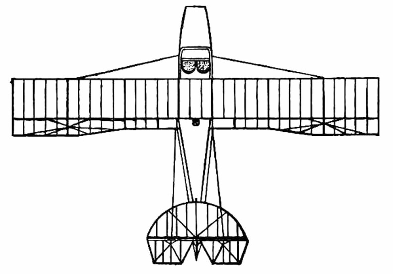
 A. Lower part of aeroplane’s hull
B. Revolving barrel to which bombs are clipped
C. Bombs
D. Re...") Bomb-releasing mechanism
Bomb-releasing mechanism
A. Lower part of aeroplane’s hull B. Revolving barrel to which bombs are clipped C. Bombs D. Releasing mechanism operated by marksman in machine. Bombs may be carried and dropped when opportunity offers; and as an improvement upon the early method, which was simply to throw these from the machine, there are releasing mechanisms now devised which carry a number of projectiles and drop them one by one as a lever is moved. The bombs, which are long, pointed, and balanced so that they will fall head first, are clipped round a barrel rather like that of a revolver, which is fixed beneath the aeroplane’s hull just below the occupants’ seat. Mechanism causes the carrying chamber to revolve and bring each bomb against a releasing catch, which—at a movement of the marksman’s lever—throws it outwards and downward. A. Wheels operating elevating-planes and rudder
B. Height recorder
C. Speaking-tube to communicate...") Control platform of an Airship
Control platform of an Airship
A. Wheels operating elevating-planes and rudder B. Height recorder C. Speaking-tube to communicate with engineers. A typical craft, representing the first of those navigated with any certainty, is shown in Figure. A...") Early-type Airship
Early-type Airship
A typical craft, representing the first of those navigated with any certainty, is shown in Figure. A gas-containing envelope, made of a light, strong, varnished fabric, is kept taut by the pressure of the gas within; the car, constructed of wood or metal tubing, is suspended by ropes from the envelope, and contains engine and crew, with a two-bladed propeller revolving astern. Such a machine, in its control, had an elevating-plane and rudder, upon the same principle as those of the aeroplane. One of the difficulties to be overcome was the expansion and contraction of gas in the envelope owing to differences in altitude and temperature. When the craft ascended, its envelope completely inflated, the gas began to dilate owing to the outer air becoming less dense; and some had to be allowed to escape through automatic valves. Then, should the machine descend to a lower level, there was not sufficient gas in the envelope to keep it tightly stretched, and it tended to sag at the bow as it was driven through the air. A. Gas envelope B. Car suspended below envelope C. Motor, which drives propeller (D) through a shaft E. Small horizontal plane for rising or descending F. Fixed fin, or keel plane, to give stability G. Rudder. showing the position of the body and the construction of the landing gear.") Grahame-White Military Biplane - front view
Grahame-White Military Biplane - front view
showing the position of the body and the construction of the landing gear.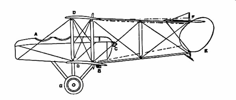
 showing shape and spread of planes and tail, and position of pilot and passenger.") Grahame-White Military Biplane
Grahame-White Military Biplane
showing shape and spread of planes and tail, and position of pilot and passenger.
 Hull of a Zeppelin during construction.
Craft of the semi-rigid type provide a link between small...") Hull of a Zeppelin during construction
Hull of a Zeppelin during construction
Hull of a Zeppelin during construction. Craft of the semi-rigid type provide a link between small, non-rigid ships and the very large machine which is built with an entirely rigid framework, and has its example in the Zeppelin. The maker forms a skeleton hull of aluminium or some light metal alloy, a method that is shown in figure. The hull of a Zeppelin, slightly more than 500 feet in length, is sheathed with tightly stretched fabric; and within it are the gas-containers—a row of seventeen separate balloons, each in a compartment by itself, and containing a total of nearly 1,000,000 cubic feet of gas—which give these airships a lifting power of close upon 30 tons. By another method, shown in figure, the sea-plane is launched from a cable suspended between two mas...") Launching a sea-plane from a wire
Launching a sea-plane from a wire
By another method, shown in figure, the sea-plane is launched from a cable suspended between two masts, and can come to rest upon the cable again after a flight has been made. The machine is hung upon the cable prior to making an ascent; then the pilot starts his engine, and as his machine glides forward along the cable he releases a catch and soars into the air. Upon returning he flies beneath the cable, and makes his craft rise until the “V”-shaped apparatus above his head is caught by the cable and the catch becomes operative; then he stops his motor, and his craft hangs from the cable as it did before. A. Sea-plane B. Cable C. The “V”-shaped apparatus which guides the cable into the clip (D.) and so suspends the machine from the wire. When petrol engines became available, they gave an impetus to the building of airships; for, like th...") Santos-Dumont’s Airship
Santos-Dumont’s Airship
When petrol engines became available, they gave an impetus to the building of airships; for, like the aeroplane, the airship needed a motive agent which gives a high power for a low weight. One of the first to use a petrol motor in an airship with success was M. Santos-Dumont, whose name has been mentioned in connection with aeroplanes. He tested small, light airships, driven by petrol engines and two-bladed propellers—as illustrated in figure; and with one of these, on a calm, still day, he flew over Paris and round the Eiffel Tower. A. Gas envelope B. Wheeled framework which carried motor, propeller, and pilot’s seat C. Elevating-plane D. Horizontal rear-plane E. Rudder. To meet the demand for a purely scouting machine, in which pilot and passenger shall have a clear fi...") Scouting Monoplane, with occupants below the wings.
Scouting Monoplane, with occupants below the wings.
To meet the demand for a purely scouting machine, in which pilot and passenger shall have a clear field for observation, both above and below, a monoplane has been designed which is called the “parasol.” This machine, a Morane-Saulnier, is shown. The two sustaining wings, forming a single surface, are raised above the body so that its occupants have nothing to impede their view earthward; and they can also see above them—an advantage of course in time of war, seeing that an enemy might be hovering overhead A. Engine and propeller B. Plane raised above hull C. Seats for pilot and passenger D. Rudder E. Elevating-plane. A coastal sea-plane, as now planned, is a craft having, say, two engines, each devolving 120 h.p., w...") Sea-plane to carry a crew of seven
Sea-plane to carry a crew of seven
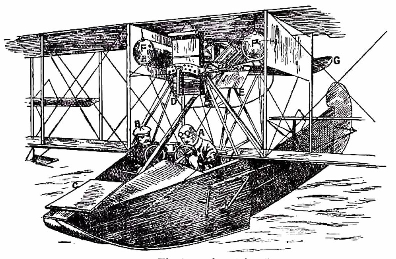
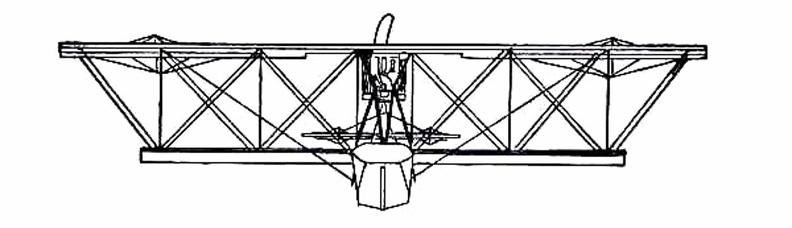
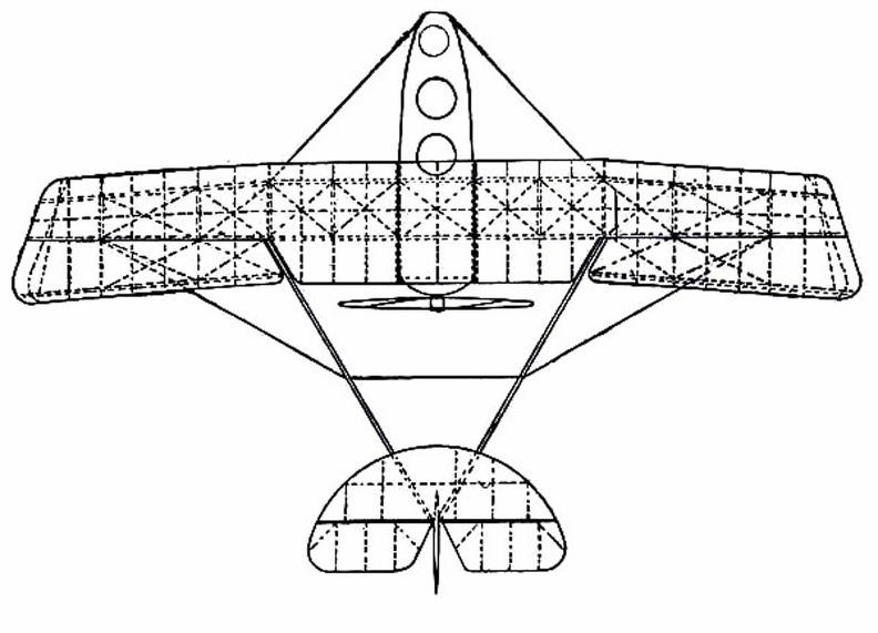
A coastal sea-plane, as now planned, is a craft having, say, two engines, each devolving 120 h.p., with a wing span of some 80 feet, and an accommodation in its hull for three men—the pilot, a combatant with a machine-gun, and an observer with an installation of wireless. But types are changing constantly, and the tendency is to build larger craft. A machine weighing a couple of tons is shown, and a novelty in regard to it is that it has wheels upon either side of its boat-shaped car, upon which it can move on land, and which fold upward when it rests upon the water. A. Hull upon which the machine floats when in the sea B.B.B. Wheels upon which it may move when on land, and which fold upward when it is on the water C. Pilot’s controlling wheel D.D. Main sustaining planes E. Four-bladed propeller driven by chain-gearing from engine within the hull. showing the large size of the elevators, the position of the pilot, and the placing of the propeller...") The Cody Biplane from above
The Cody Biplane from above
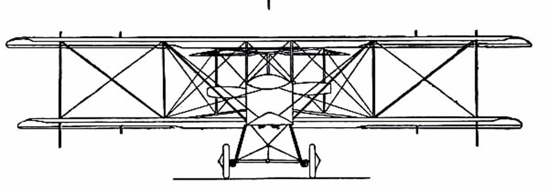
showing the large size of the elevators, the position of the pilot, and the placing of the propellers. Another ardent worker in England, and one destined to become famous, was Mr. S. F. Cody. After devel...") The Cody Biplane
The Cody Biplane
Another ardent worker in England, and one destined to become famous, was Mr. S. F. Cody. After developing a system of man-lifting kites which the British War Office acquired, he joined the military aircraft factory that had been established at Farnborough. Here, after tests with dirigible balloons, he began the construction of experimental biplanes—all machines of large size. Early in 1909 he made brief flights—the longest being one of about 250 yards. Then, after alterations to his machine, he managed in July to fly a distance of 4 miles. This he increased afterwards to 8 miles; and then on 1st September flew for 1 hour 3 minutes, rising to a height of 300 feet. Cody’s biplane was a very large machine, having 1000 square feet of lifting surface—twice that of the Farman or Voisin. Driving it was an 80-h.p. engine, which operated two propellers on the system used by the Wrights. With its pilot on board the machine weighed 2170 lbs. A. Elevating-planes and vertical-plane B. Pilot’s control lever C.C. Main-planes D. Motor E. Propellers F. Rudder G. Landing gear H. Rear skid. A machine that has achieved success, owing to its power of varying speed, is the Sopwith military bi...") Sopwith Military Biplane
Sopwith Military Biplane
A machine that has achieved success, owing to its power of varying speed, is the Sopwith military biplane. Adopting a practice that has become general, its wings are fitted upon what is practically a monoplane body. Tail-planes and rudder are the same as in a monoplane. The top main-plane, as will be seen, is set slightly in advance of the lower. The system is called “staggering”; and the idea is that, by placing the upper plane ahead of the lower, the total lifting power will be increased. It has been proved a disadvantage of the biplane that, when the main-planes are placed one above another, there is a slight loss of lift owing to the fact that, acting upon the air as they do quite close to each other, a certain amount of interference occurs between them—one tending to disturb the air-stream in which the other moves. By “staggering” the two planes this interference is overcome; but some makers regard it as a small consideration, and build their planes in the ordinary way, allowing as large a gap as possible between them. In the Sopwith military machine, engine and propeller are in front of the main-planes; then come the places for pilot and observer. The pilot sits first, and the body of the machine is so high that only his head appears above it, while just in front of his face, to deflect the wind-rush from the propeller, there is a raised section of the hull which acts as a screen. Behind the pilot, sitting in a second opening in the hull, is the observer. He has a view forward, rendered the better by setting back the lower-plane; while at the point at which it joins the body of the machine, immediately below him, this plane is hollowed out, so that he can look directly upon the earth below. Small windows are also fitted upon either side of the hull. Through those in front the pilot may glance when descending from a flight, so as to judge his distance from the ground, while the others are utilised by the observer, as he turns to look from side to side. This biplane, and many others, is balanced against sideway roll by ailerons, and not by warping the wings. Constant warping, such as is necessary in the everyday use of machines, has been declared to strain a plane and render it weak; therefore the use of ailerons is now favoured. A. Propeller B. Motor, partly hidden by shield C.C. Main-planes D. Pilot’s seat E. Observer’s seat F. Outlook windows in side of hull G. Rudder H. Elevating-plane I. Landing gear. showing the spread of the planes and tail, and the delicate taper of the long, canoe-shaped body.") The Antoinette Monoplane - top view
The Antoinette Monoplane - top view
showing the spread of the planes and tail, and the delicate taper of the long, canoe-shaped body. At the beginning of 1909 a new monoplane made its appearance in France—a powerful, finely construc...") The Antoinette Monoplane
The Antoinette Monoplane
At the beginning of 1909 a new monoplane made its appearance in France—a powerful, finely constructed, and very stable machine. It was the Antoinette, designed by a famous engineer, and it was this craft which interested Latham. M. Levavasseur was the designer of it and of a specially lightened motor, first applied to motor-boats, and afterwards to the experimental biplane of M. Santos-Dumont and also to the aeroplane with which Farman first flew. The Antoinette, which M. Levavasseur also fitted with one of his motors, was a large monoplane—far larger than the Bleriot; and built not with the idea of being a fair-weather machine, but to fly in winds. The span of its wings was 46 feet, and they contained 365 square feet of sustaining surface, while the total weight was 1040 lbs. A. Propeller B. Motor C. Sustaining-plane D. Pilot’s seat and controlling wheel E.E. Vertical rudders F. Elevating-plane G. Landing gear. The Bleriot Monoplane - top view showing its bird-like shape and the position of the pilot.") The Bleriot Monoplane - top view
The Bleriot Monoplane - top view
The Bleriot Monoplane - top view showing its bird-like shape and the position of the pilot. A. Propeller
B. Motor
C. Sustaining-plane
D. Pilot’s seat
E. Landing chassis
F. Combined tail...") The Bleriot Monoplane
The Bleriot Monoplane
A. Propeller B. Motor C. Sustaining-plane D. Pilot’s seat E. Landing chassis F. Combined tail and elevating-planes G. Rudder. An experimenter who braved this apathy and won his way until he became a constructor of aircraft, wa...") The Roe Triplane
The Roe Triplane
An experimenter who braved this apathy and won his way until he became a constructor of aircraft, was Mr. A. V. Roe. For some time he was an advocate of the triplane form of machine—a craft, that is to say, with three main-planes fitted one above another. The machine with which he obtained flights, although they were very brief, is seen in the figure. Subsequently, however, Mr. Roe adopted the biplane form. His distinction in the pioneer days was that he managed to make his triplane lift into the air and fly a short distance, with the aid of a motor-cycle engine developing no more than 9 h.p. A.A.A. Three main-planes B. Motor C. Four-bladed propeller D.D.D. Triplane tail E. Rudder F. Landing gear. The Voisin Biplane - top view") The Voisin Biplane - top view
The Voisin Biplane - top view
The Voisin Biplane - top view At the beginning of 1909 there were two types of successful aeroplane—the Wright and the Voisin. B...") The Voisin Biplane
The Voisin Biplane
At the beginning of 1909 there were two types of successful aeroplane—the Wright and the Voisin. Bleriot had flown with his monoplane and flown well; but he was still in the process of evolving a practical machine, and several other inventors were in a similar stage. It was the Wright and the Voisin which had proved their worth; and the Wright, as has been said, was the better of the two. Of the Voisin, as flown in 1909, a reproduction is given in the figure. It was a heavier aeroplane than the Wrights’, owing largely to the weight of its alighting gear (250 lbs.) and of its big balancing tail (more than 100 lbs.); hence the necessity for using a 50-h.p. motor, which drove a two-bladed metal propeller at the rate of 1200 revolutions a minute. The Voisin brothers, and other French makers, did not approve of the two-propeller system of the Wrights: they preferred one screw, revolving at high speed. But there was no doubt—at any rate in this stage of aviation—that the Wright method was more efficient than that of the Frenchmen. It was calculated, indeed, that the Wright biplane, when actually in the air, could be driven at an expenditure of only 15 h.p.; whereas the Voisin, even with its 50-h.p. motor running at full speed, had only just enough power to fly. A. Elevating plane B. Pilot’s seat C.C. Main-planes D. Engine and propeller E. Landing chassis F. Balancing tail G. Rudder. There needs to be an equipment of spare machines also; and a number of travelling workshops with ski...") Travelling workshop for the repair of military aeroplanes
Travelling workshop for the repair of military aeroplanes
There needs to be an equipment of spare machines also; and a number of travelling workshops with skilled engineers, which can be rushed from place to place for the repair of damaged craft. A sketch of one of these workshops on wheels, which are vital to the organisation, is seen in the figure Of famous aeroplanes at Rheims, five types stood out by themselves—the Farman, the Voisin, the Wri...") The Curtiss Biplane
The Curtiss Biplane
Of famous aeroplanes at Rheims, five types stood out by themselves—the Farman, the Voisin, the Wright, the Bleriot, and the Antoinette, all of which have been described. But there was one other, which few people had heard of before it appeared here. This was the Curtiss biplane, built by an American named Glenn H. Curtiss, and engined with a motor which also bore his name. Curtiss had experimented with many power-driven machines—motor-cycles, motor-cars, airships, and aeroplanes—and had won a prize in America with a small, light biplane, and it was a craft of this type—as seen in the figure —that he brought with him to Rheims, his idea being to compete for the speed prize. The machine had a front elevator and tail-planes, according to the practice in biplane construction; but an innovation was the setting of the ailerons midway between the main-planes—a position that will be noted in the sketch; another novelty was the way these ailerons operated. At the pilot’s back, as he sat in his driving seat, was an upright rod with two shoulder-pieces—by means of which, should he shift his body, he could swing the rod from side to side. Wires ran from the rod to the ailerons; and if the pilot leaned over, say, to the right, he drew down the ailerons on the left side of the machine. The merit of such a control was that it was instinctive; that is to say, should the biplane tip down on one side, it was natural for the pilot to lean away from the plane-ends that were sinking; and he operated the ailerons automatically, as he did this, and so brought the machine level again. A. Elevating-planes B. Pilot’s seat and control-wheel C.C. Main-planes D. Ailerons E. Motor and propeller F. Tail-plane and rudder. Kicking the football") Kicking the football
Kicking the football
Kicking the football Catching the football") Catching the football
Catching the football
Catching the football