


Patent Iron Suspension Railroad Bridge.
The undersigned would inform the officers of Railroads ...") Wendell Bollmans Patent Bridge
Wendell Bollmans Patent Bridge
Patent Iron Suspension Railroad Bridge. The undersigned would inform the officers of Railroads and others, that he is prepared to furnish Drawings and Estimates for Bridges, Roofs, etc., on the plan of Bollman’s Patent. The performance of these bridges, some of which have been in use for six years, has given entire satisfaction. Their simplicity of construction renders repairs easy and cheap, and by a peculiar connection of the Main and Panel Rods at the bottom of the Posts, all danger from the effects of expansion, which has heretofore been the chief objection to Iron Bridges, is entirely removed. J. H. TEGMEYER, Baltimore, Md. We must remember that travelling was no such simple and easy matter then as it is now. As the plante...") Washington's Coach
Washington's Coach
We must remember that travelling was no such simple and easy matter then as it is now. As the planters in Virginia usually lived on the banks of one of the many rivers, the simplest method of travel was by boat, up or down stream. There were cross-country roads, but these at best were rough, and sometimes full of roots and stumps. Often they were nothing more than forest paths. In trying to follow such roads the traveler at times lost his way and occasionally had to spend a night in the woods. But with even such makeshifts for roads, the planter had his lumbering old coach to which, on state occasions, he harnessed six horses and drove in great style. A singular instance of the wagon and funeral-boat in combination has been found on the bandage of a ...") Wagon and Boat, from a mummy bandage
Wagon and Boat, from a mummy bandage
A singular instance of the wagon and funeral-boat in combination has been found on the bandage of a mummy, now preserved in the collection of S. d'Athanasi. It is supposed by some modern authors that Herodotus, in speaking of the religious ceremonies in honor of Mars, as performed in the city of Pampremis, refers to this vehicle. Among other things, he tells us that the priests placed an image in a wooden temple, gilded all over, which they carried to a sacred dwelling; "then the few who were left about the image draw a four-wheeled carriage containing the temple and the image." The grand canal of China, or rather the water communication between the northern and southern extrem...") View on the Great Canal
View on the Great Canal
The grand canal of China, or rather the water communication between the northern and southern extremities of the empire by a succession of canals and rivers, is certainly the first inland navigation in the world. The multitude of vessels, of every size and shape, is not to be estimated. The large one in the print is one of those which carried the British embassador and his suite up the Pei-ho to the neighbourhood of Pekin, which were in every respect comfortable and commodious. On passing bridges, which are very frequent in the neighbourhood of all towns and villages, the masts are usually lowered down; but many of the bridges are lofty enough to admit the smaller kind of barges to pass underneath with their masts standing. The bridges are almost as various in their shape and construction as the barges, and some of them by no means destitute of taste. The article upon the Velocipede in the \" American Encyclopedia,\" commences by giving the well-known ...") Velocipedes
Velocipedes
The article upon the Velocipede in the " American Encyclopedia," commences by giving the well-known derivation of the word from the Latin velox, swift, and pes, a foot, and defines it as a carriage, by means of which the rider propels himself along the ground, and states that it was invented at Manheim. We present a bicycle for ladies, lately invented and patented by Messrs. Pickering & Davis of New Yo...") Velocipede for Ladies
Velocipede for Ladies
We present a bicycle for ladies, lately invented and patented by Messrs. Pickering & Davis of New York City. It will be seen that the reach or frame, instead of forming a nearly straight line from the front swivel to the hind axle, follows the curve of the front wheel until it reaches a line nearly as low as the hind axle when it runs horizontally to that point of the hind wheel. The two wheels being separated three or four inches, allow of an upright rod being secured to the reach; around this is a spiral spring, on which a comfortable, cane-seated, willow-backed chair is placed. This machine, with a moderate-sized wheel (of thirty to thirty-three inches), will allow being driven with a great deal of comfort and all the advantages of the two-wheel veloce. In mounting, a lady has to step over the reach, at a point only twelve inches from the floor, the height of an ordinary step in a flight of stairs.") Under Carriage of Coach
Under Carriage of Coach If you have to take a side road on the right, keep your arm stretched out in horizontal direction o...") Turn Signal
Turn Signal
If you have to take a side road on the right, keep your arm stretched out in horizontal direction outside the car. [Translated online from the Dutch ] Just below Widdin, at the Bulgarian town of Arčer Palanka, the general course of the Danube changes...") Turkish Vessels
Turkish Vessels
Just below Widdin, at the Bulgarian town of Arčer Palanka, the general course of the Danube changes from the south to the east; and to the town of Cernavoda, in the Dobrudscha, about 300 miles below, the river keeps the latter direction with few and slight deviations. The long, straight reaches were here enlivened by many sailing-vessels of the fifteenth-century type, with high ornate sterns, and single mast set midway between the bow and stern. Sometimes we met them gayly ploughing their way up-stream, with every bellying sail drawing full, and again we saw them dragged slowly against the current by a long line of patient Turkish sailors harnessed to a tow-rope; or else we came across them tied to the trees in some quiet spot awaiting a favorable wind, the decks covered with sleeping sailors, no man on watch. Turkish Sailing Lotka, Sulina") Turkish Sailing Lotka, Sulina
Turkish Sailing Lotka, Sulina
Turkish Sailing Lotka, Sulina There needs to be an equipment of spare machines also; and a number of travelling workshops with ski...") Travelling workshop for the repair of military aeroplanes
Travelling workshop for the repair of military aeroplanes
There needs to be an equipment of spare machines also; and a number of travelling workshops with skilled engineers, which can be rushed from place to place for the repair of damaged craft. A sketch of one of these workshops on wheels, which are vital to the organisation, is seen in the figure The Wright Brothers Aero Engine") The Wright Brothers Aero Engine
The Wright Brothers Aero Engine
The Wright Brothers Aero Engine The Voisin Biplane - top view") The Voisin Biplane - top view
The Voisin Biplane - top view
The Voisin Biplane - top view At the beginning of 1909 there were two types of successful aeroplane—the Wright and the Voisin. B...") The Voisin Biplane
The Voisin Biplane
At the beginning of 1909 there were two types of successful aeroplane—the Wright and the Voisin. Bleriot had flown with his monoplane and flown well; but he was still in the process of evolving a practical machine, and several other inventors were in a similar stage. It was the Wright and the Voisin which had proved their worth; and the Wright, as has been said, was the better of the two. Of the Voisin, as flown in 1909, a reproduction is given in the figure. It was a heavier aeroplane than the Wrights’, owing largely to the weight of its alighting gear (250 lbs.) and of its big balancing tail (more than 100 lbs.); hence the necessity for using a 50-h.p. motor, which drove a two-bladed metal propeller at the rate of 1200 revolutions a minute. The Voisin brothers, and other French makers, did not approve of the two-propeller system of the Wrights: they preferred one screw, revolving at high speed. But there was no doubt—at any rate in this stage of aviation—that the Wright method was more efficient than that of the Frenchmen. It was calculated, indeed, that the Wright biplane, when actually in the air, could be driven at an expenditure of only 15 h.p.; whereas the Voisin, even with its 50-h.p. motor running at full speed, had only just enough power to fly. A. Elevating plane B. Pilot’s seat C.C. Main-planes D. Engine and propeller E. Landing chassis F. Balancing tail G. Rudder. Already, anticipating war in the air, a fighting aeroplane has been evolved; and a machine of this t...") The Vickers
The Vickers
Already, anticipating war in the air, a fighting aeroplane has been evolved; and a machine of this type is shown in Figure. The body, in which pilot and gunner sit, is armoured lightly with plates which will resist the penetration of a bullet. Such armouring was found necessary after the use of aeroplanes in Tripoli and the Balkans. When flying unavoidably low in these campaigns, and when fired at from the ground, the wooden bodies of machines were pierced by shot, and in several instances their occupants wounded. A fighting aeroplane A. Machine-gun projecting from opening in bow B. Gunner’s position C. Pilot’s seat D.D. Side windows for observation E. Engine and propeller. The Tube") The Tube
The Tube
The Tube Messrs. Forest and Son received a design and order for the construction of a steel boat 28 ft. long,...") The Steel Boat 'Advance'
The Steel Boat 'Advance'
Messrs. Forest and Son received a design and order for the construction of a steel boat 28 ft. long, 6 ft. beam, and 2 ft. 6 in. deep. It was to be built of Siemens steel galvanized, and divided into twelve sections, each weighing about 75 lbs. The fore and aft sections were to be decked and watertight, to give buoyancy in case of accident.") The Stage Coach
The Stage Coach In 1830 all this had disappeared, and we find in Mr. Nasmyth's sketch a regular fire-box, such as is...") The Rocket 1830
The Rocket 1830
In 1830 all this had disappeared, and we find in Mr. Nasmyth's sketch a regular fire-box, such as is used to this moment. In one word, the Rocket of 1829 is different from the Rocket of 1830 in almost every conceivable respect; and we are driven perforce to the conclusion that the Rocket of 1829 never worked at all on the Liverpool and Manchester Railway; the engine of 1830 was an entirely new engine.") The Result of Feather-Edging
The Result of Feather-Edging") The Mail's Meeting
The Mail's Meeting") The Mail Coach
The Mail Coach") The Holyhead and Chester Mails
The Holyhead and Chester Mails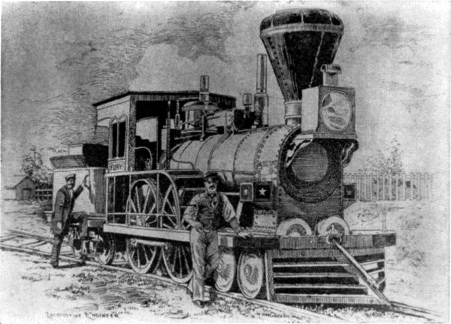 The Fury
The “Fury,” built for the Boston and Worcester Railroad in 1849 by Wilmarth. It was known as a “Shanghai” because of its great height. It was called the 'Locomotion.' George Stephenson stood ready to drive it as soon as the trucks, whi...") The first Railway Journey in England
The first Railway Journey in England
It was called the 'Locomotion.' George Stephenson stood ready to drive it as soon as the trucks, which a stationary engine was lowering down the slope by means of a wire rope, had been attached to it. In the first of these trucks came the Directors of the Railway Company and their friends, followed by twenty-one trucks (all open to the sky, like ordinary goods-trucks), loaded with various passengers, and finally six more waggons of coal. Such was the first train. A man on horseback, carrying a flag, having taken up his position in front of the 'Locomotion' to head the procession, the starting word was given, and with a hiss of steam, half drowned in the shouting of the crowd, the first railway journey ever made in England was begun. Our afternoon cruise was not further remarkable except for the sight of various immense ferry-boats ...") The Ferry
The Ferry
Our afternoon cruise was not further remarkable except for the sight of various immense ferry-boats swinging across the stream attached to wire guys and bearing two great loads of hay, cattle and all, and for a visit to Ingolstadt, a military post of great importance and correspondingly unattractive aspect. showing the span of main-planes, elevator, and tail, also the positions of landing gear and pilot’...") The Farman Biplane - top view
The Farman Biplane - top view
showing the span of main-planes, elevator, and tail, also the positions of landing gear and pilot’s seat.
In July, at Rheims, there was to be the great flying meeting; and Farman had made up his mind to...") The Farman Biplane
The Farman Biplane
In July, at Rheims, there was to be the great flying meeting; and Farman had made up his mind to wait for this. Aided by the experience he had gained with the Voisin machine, he had designed a craft which should be generally more efficient and faster in flight, and more quickly responsive to its controls. The biplane he produced, marking as it did a step forward in construction, is a machine that needs description. The general appearance of the craft is indicated by Fig. 46, while an illustration of this type of machine in flight will be found on Plate VII. A feature of the Voisin that Farman discarded was the vertical panel fitted between the main-planes to give sideway stability. An objection to these planes was that they added to the weight of the machine and checked its speed, tending also to drive it from its course should there be a side wind. But in taking away such fixed balancing-planes, Farman had to substitute another device; and what he did was to work upon the same theory as the Wrights had done, and obtain a similar result in a different way. They, it will be remembered, had warped the rear portions of their main-planes. Farman kept his planes rigid, but fitted to their rear extremities four narrow, hinged planes, or flaps, which could be moved up and down and were called ailerons. Their effect was the same as with the Wright wing-warp. When a gust tilted the machine, the pilot drew down the ailerons upon the side that was inclined downward; whereupon the air-pressure, acting upon the drawn-down surfaces, restored the machine to an even keel. A. Elevating-plane; B.B. Main-planes; C. Pilot’s seat; D. Motor and propeller; E. Petrol tank; F.F. Hinged balancing-planes, or ailerons; G.G. Tail-planes; H.H. Twin vertical rudders; I. Landing wheels and skid") The Devonport Mail near Amsbury going post through a drift of snow
The Devonport Mail near Amsbury going post through a drift of snow The Curtiss Biplane making a turn") The Curtiss Biplane making a turn
The Curtiss Biplane making a turn
The Curtiss Biplane making a turn The Curtiss Biplane in flight") The Curtiss Biplane in flight
The Curtiss Biplane in flight
The Curtiss Biplane in flight showing the chassis and the position between the planes of the two ailerons (A.A.).") The Curtiss Biplane front view
The Curtiss Biplane front view
showing the chassis and the position between the planes of the two ailerons (A.A.). Of famous aeroplanes at Rheims, five types stood out by themselves—the Farman, the Voisin, the Wri...") The Curtiss Biplane
The Curtiss Biplane
Of famous aeroplanes at Rheims, five types stood out by themselves—the Farman, the Voisin, the Wright, the Bleriot, and the Antoinette, all of which have been described. But there was one other, which few people had heard of before it appeared here. This was the Curtiss biplane, built by an American named Glenn H. Curtiss, and engined with a motor which also bore his name. Curtiss had experimented with many power-driven machines—motor-cycles, motor-cars, airships, and aeroplanes—and had won a prize in America with a small, light biplane, and it was a craft of this type—as seen in the figure —that he brought with him to Rheims, his idea being to compete for the speed prize. The machine had a front elevator and tail-planes, according to the practice in biplane construction; but an innovation was the setting of the ailerons midway between the main-planes—a position that will be noted in the sketch; another novelty was the way these ailerons operated. At the pilot’s back, as he sat in his driving seat, was an upright rod with two shoulder-pieces—by means of which, should he shift his body, he could swing the rod from side to side. Wires ran from the rod to the ailerons; and if the pilot leaned over, say, to the right, he drew down the ailerons on the left side of the machine. The merit of such a control was that it was instinctive; that is to say, should the biplane tip down on one side, it was natural for the pilot to lean away from the plane-ends that were sinking; and he operated the ailerons automatically, as he did this, and so brought the machine level again. A. Elevating-planes B. Pilot’s seat and control-wheel C.C. Main-planes D. Ailerons E. Motor and propeller F. Tail-plane and rudder. The conveyance of a Persian official traveling in disgrace to Teheran at the call of the shah") The conveyance of a Persian official traveling in disgrace to Teheran at the call of the shah
The conveyance of a Persian official traveling in disgrace to Teheran at the call of the shah
The conveyance of a Persian official traveling in disgrace to Teheran at the call of the shah showing the large size of the elevators, the position of the pilot, and the placing of the propeller...") The Cody Biplane from above
The Cody Biplane from above
showing the large size of the elevators, the position of the pilot, and the placing of the propellers. Another ardent worker in England, and one destined to become famous, was Mr. S. F. Cody. After devel...") The Cody Biplane
The Cody Biplane
Another ardent worker in England, and one destined to become famous, was Mr. S. F. Cody. After developing a system of man-lifting kites which the British War Office acquired, he joined the military aircraft factory that had been established at Farnborough. Here, after tests with dirigible balloons, he began the construction of experimental biplanes—all machines of large size. Early in 1909 he made brief flights—the longest being one of about 250 yards. Then, after alterations to his machine, he managed in July to fly a distance of 4 miles. This he increased afterwards to 8 miles; and then on 1st September flew for 1 hour 3 minutes, rising to a height of 300 feet. Cody’s biplane was a very large machine, having 1000 square feet of lifting surface—twice that of the Farman or Voisin. Driving it was an 80-h.p. engine, which operated two propellers on the system used by the Wrights. With its pilot on board the machine weighed 2170 lbs. A. Elevating-planes and vertical-plane B. Pilot’s control lever C.C. Main-planes D. Motor E. Propellers F. Rudder G. Landing gear H. Rear skid. The Clermont
Fulton returned in 1806 to America, where, with money furnished by his friend Livingst...") The Clermont
The Clermont
The Clermont Fulton returned in 1806 to America, where, with money furnished by his friend Livingston, he began to construct another steamboat which he called the Clermont, after the name of Livingston's home on the Hudson. This boat was 130 feet long and 18 feet wide, with a mast and a sail, and on each side a wheel 15 feet in diameter, fully exposed to view. One morning in August, 1807, a throng of expectant people gathered on the banks of the North River at New York, to see the trial of the Clermont. Everybody was looking for failure. People had all along spoken of Fulton as a crack-brained dreamer, and had called the Clermont "Fulton's Folly." "Of course the thing would not move." "That any man with common-sense might know," they said. So while Fulton was waiting to give the signal to start, these wiseacres were getting ready to jest at his failure. Finally, at the signal, the Clermont moved slowly, and then stood perfectly still. "Just what I have been saying," said one onlooker with emphasis. "I knew the boat would not go," said another. "Such a thing is impossible," said a third. But they spoke too soon, for after a little adjustment of the machinery, the Clermont steamed proudly up the Hudson. The Bleriot Monoplane - top view showing its bird-like shape and the position of the pilot.") The Bleriot Monoplane - top view
The Bleriot Monoplane - top view
The Bleriot Monoplane - top view showing its bird-like shape and the position of the pilot. A. Propeller
B. Motor
C. Sustaining-plane
D. Pilot’s seat
E. Landing chassis
F. Combined tail...") The Bleriot Monoplane
The Bleriot Monoplane
A. Propeller B. Motor C. Sustaining-plane D. Pilot’s seat E. Landing chassis F. Combined tail and elevating-planes G. Rudder.") The Birmingham Mail near Aylesbury
The Birmingham Mail near Aylesbury Of the various kinds of velocipedes, four, three, two, and one wheeled, the bicycle seems to be cons...") The Bicycle
The Bicycle
Of the various kinds of velocipedes, four, three, two, and one wheeled, the bicycle seems to be considered the most artistic, is altogether the most in favor, and steadily maintains its ground against all rivals. Whether it will be the model velocipede of the future remains to be seen. The various experiments now being tried will, no doubt, eventually result in a nearly perfect machine, but it will require a season's experience fully to develop the ingenuity of our American artisans. Many have expressed doubts as to the real utility of the velocipede, and the permanency of its use. They seem to think it a frivolous invention only calculated to serve purposes of amusement, and soon to be superseded by some other ephemeral claimant for popularity. Most of these have based their opinions upon the disuse into which rude machines have fallen in former times. But the difference in the construction of the modern velocipede from the primitive one has entirely changed the character of the vehicle. It is no longer a draft vehicle, but a locomotive, and as much superior to the original bar on wheels, as the improved steam locomotive is to the old-time stage-coach. It was on June 5, 1783 that Stephen and Joseph Montgolfier, two French brothers, sent up the first b...") The ascension of Montgolfier’s balloon
The ascension of Montgolfier’s balloon
It was on June 5, 1783 that Stephen and Joseph Montgolfier, two French brothers, sent up the first balloon. You can just imagine the amazement it caused when it arose from the ground. showing the spread of the planes and tail, and the delicate taper of the long, canoe-shaped body.") The Antoinette Monoplane - top view
The Antoinette Monoplane - top view
showing the spread of the planes and tail, and the delicate taper of the long, canoe-shaped body. At the beginning of 1909 a new monoplane made its appearance in France—a powerful, finely construc...") The Antoinette Monoplane
The Antoinette Monoplane
At the beginning of 1909 a new monoplane made its appearance in France—a powerful, finely constructed, and very stable machine. It was the Antoinette, designed by a famous engineer, and it was this craft which interested Latham. M. Levavasseur was the designer of it and of a specially lightened motor, first applied to motor-boats, and afterwards to the experimental biplane of M. Santos-Dumont and also to the aeroplane with which Farman first flew. The Antoinette, which M. Levavasseur also fitted with one of his motors, was a large monoplane—far larger than the Bleriot; and built not with the idea of being a fair-weather machine, but to fly in winds. The span of its wings was 46 feet, and they contained 365 square feet of sustaining surface, while the total weight was 1040 lbs. A. Propeller B. Motor C. Sustaining-plane D. Pilot’s seat and controlling wheel E.E. Vertical rudders F. Elevating-plane G. Landing gear. Telegraph and Railroad") Telegraph and Railroad
Telegraph and Railroad
Telegraph and Railroad Swerving at intersections") Swerving at intersections
Swerving at intersections
Swerving at intersections With an open torpedo, the stop signal can also be given by sticking the arm straight up. In any case...") Stop Signal
Stop Signal
With an open torpedo, the stop signal can also be given by sticking the arm straight up. In any case, account must then be taken of the somewhat higher rear of the car, or of the possibility that the passengers behind are masking the movement of the arm. [Translated online from the Dutch ] The woodcut shows the style of carriage associated—grotesquely associated, it seems to our eyes—...") State Carriage of the Fourteenth Century
State Carriage of the Fourteenth Century
The woodcut shows the style of carriage associated—grotesquely associated, it seems to our eyes—with the armour and costume of the Middle Ages. It might represent Duke Theseus going in state through the streets of Athens, hung with tapestry and cloth of gold, to the solemn deed of arms of Palamon and Arcite. Some types of American and foreign aeroplanes") Some types of American and foreign aeroplanes
Some types of American and foreign aeroplanes
Some types of American and foreign aeroplanes Some types of American and foreign aeroplanes") Some types of American and foreign aeroplanes
Some types of American and foreign aeroplanes
Some types of American and foreign aeroplanes Shop engine, 1901") Shop engine, 1901
Shop engine, 1901
Shop engine, 1901 But as airships were built larger, and greater speeds were obtained, it became necessary to strength...") Semi-rigid Airship
Semi-rigid Airship
But as airships were built larger, and greater speeds were obtained, it became necessary to strengthen the envelopes with some form of keel; and this led to a type which is known as the semi-rigid, and is developed successfully in France. The figure illustrates an airship of this build. Along the lower side of its envelope is placed a light, rigid framework or keel, and from this is suspended the car which contains engines and crew. A. Gas-containing envelope B. Strengthening keel C.C. Stabilising-planes D. Rudder E. Car carrying engines, propeller, and crew. When petrol engines became available, they gave an impetus to the building of airships; for, like th...") Santos-Dumont’s Airship
Santos-Dumont’s Airship
When petrol engines became available, they gave an impetus to the building of airships; for, like the aeroplane, the airship needed a motive agent which gives a high power for a low weight. One of the first to use a petrol motor in an airship with success was M. Santos-Dumont, whose name has been mentioned in connection with aeroplanes. He tested small, light airships, driven by petrol engines and two-bladed propellers—as illustrated in figure; and with one of these, on a calm, still day, he flew over Paris and round the Eiffel Tower. A. Gas envelope B. Wheeled framework which carried motor, propeller, and pilot’s seat C. Elevating-plane D. Horizontal rear-plane E. Rudder. It is also important to know, if you have to go through or along somewhere close with your car, what...") Room to pass
Room to pass
It is also important to know, if you have to go through or along somewhere close with your car, what width you need. That can become such a certainty for you that it will look like virtuosity to the uninitiated. It's a matter of routine, of course, but it can be extremely practiced. It must be started with calculating the extreme points of the fenders. Later on, even this aid is often redundant. The best way to learn this is to place two blocks of wood on the ground, or to drive two posts, which are measured just the width of the wagon apart. Riding on that is the means of learning to estimate a narrow passage. Is the width wide enough to pass, but what When measured tight, keep flat on the side of the traffic obstruction, which is on your and steering wheel side. After all, here you can see exactly how close you can get without the risk of a collision. The other side will then be free of itself. [Translated online from the Dutch ] Rear elevation of Pioneer and detail of valve shifter; valve face and valve. (Drawing by J. H. White...") Rear elevation of Pioneer
Rear elevation of Pioneer
Rear elevation of Pioneer and detail of valve shifter; valve face and valve. (Drawing by J. H. White.) An early primitive sledge") Primitive Sledge
Primitive Sledge
An early primitive sledge “Pioneer” locomotive. (1) Air chamber, (2) reversing lever, (3) counterweight, (4) reversing sha...") Pioneer Locomotive
Pioneer Locomotive
“Pioneer” locomotive. (1) Air chamber, (2) reversing lever, (3) counterweight, (4) reversing shaft, (5) link hanger, (6) rocker, (7) feedwater line to boiler, (8) link block, (9) link, (10) eccentric, (11) pump plunger, (12) pump steamheater line, (13) feedwater pump, (14) wire netting [bonnet], (15) deflecting cone, (16) stack, (17) stack hopper. (Drawing by J. H. White.) “Pioneer” locomotive. (Drawing by J. H. White.)") Pioneer Locomotive
Pioneer Locomotive
“Pioneer” locomotive. (Drawing by J. H. White.) “Pioneer” locomotive,
(1) Safety valve,
(2) spring balance,
(3) steam jet
(4) dry pipe
(5...") Pioneer Locomotive
Pioneer Locomotive
“Pioneer” locomotive, (1) Safety valve, (2) spring balance, (3) steam jet (4) dry pipe (5) throttle lever (6) throttle (7) crown bar (8) front tube sheet (9) check valve (10) top rail (11) rear-boiler bracket (12) pedestal (13) rocker bearing (14) damper (15) grate (16) bottom rail (17) pump heater valve (18) cylinder lubricator (19) reversing lever (20) brake shoe (21) mud ring (22) blowoff cock (23) ashpan (Drawing by J. H. White.) Pilot and passenger") Pilot and passenger
Pilot and passenger
Pilot and passenger