


 The royal assent was given on September 22, 1831, to \"An Act to amend the laws relating to Hackney C...") London Cab
London Cab
The royal assent was given on September 22, 1831, to "An Act to amend the laws relating to Hackney Carriages," etc., by which it was enacted that, up to January 5, 1833, they should be limited to twelve hundred, and, after that date, there was to be no limitation to their number, except that caused by the law of demand and supply. The hackney coach was a cumbrous vehicle with two horses, and, in 1823, one-horsed vehicles were introduced, called cabriolets, speedily shortened into cabs. The hackney coach was a cumbrous vehicle with two horses, and, in 1823, one-horsed vehicles were int...") London Cabriolet
London Cabriolet
The hackney coach was a cumbrous vehicle with two horses, and, in 1823, one-horsed vehicles were introduced, called cabriolets, speedily shortened into cabs. They began modestly with twelve, and in 1831 had increased to one hundred and sixty-five. On December 23, 1834, Joseph Aloysius Hansom, an architect, took out a patent, No. 6733, for \"a vehi...") London cabriolet
London cabriolet
On December 23, 1834, Joseph Aloysius Hansom, an architect, took out a patent, No. 6733, for "a vehicle for conveying loads, etc.," and from that time to this his name has been inseparably connected in England with cabs. Not that his cab was like the present "hansom," which is a product of much evolution. There was no back seat for the driver, and its "safety" consisted in its cranked axle. He sold his rights to a company for £10,000, but never got a penny piece of it. The only money he ever got out of it was £300, which, when the company had got into a muddle, was paid him to take temporary management and put things straight again. Lumber Raft") Lumber Raft
Lumber Raft
Lumber Raft Man and wife about to go away in the bridal car") Man and wife about to go away in the bridal car
Man and wife about to go away in the bridal car
Man and wife about to go away in the bridal car Zimmerman and his machine") Man with a bicycle
Man with a bicycle
Zimmerman and his machine When putting the car in place in the garage you must also maneuver carefully. The main thing is that...") Methods to get to the right place in a garage
Methods to get to the right place in a garage
When putting the car in place in the garage you must also maneuver carefully. The main thing is that you get in your place and as best you can. Too much brio results in broken walls and bent mudguards. If it makes you nervous, this twisting back and forth, feel free to leave it to someone else. It is not everyone's job and it is precisely with this shunting that small causes can have major consequences. [Translated online from the Dutch ] Wherever there are real roads in Mexico, there you may see the quaint old-fashioned ox-carts with wh...") Mexican Ox-cart
Mexican Ox-cart
Wherever there are real roads in Mexico, there you may see the quaint old-fashioned ox-carts with wheels often made from solid blocks of wood cut to shape. Two oxen are generally yoked to each, but when heavy loads are to be dragged, four, six, or even more are used at once. On the Tile-boat") On the Tile-boat
On the Tile-boat
On the Tile-boat When overtaking a tram, also pay attention to the possibility that someone will jump in front of or ...") Overtaking a tram
Overtaking a tram
When overtaking a tram, also pay attention to the possibility that someone will jump in front of or from the tram. Giving a good signal and leaving as much road width as possible between the tram and your car is required. To catch up with a steam tram that hurls its plume over the road, and you it obstructs the view, it is advisable to wait until the wind chases away the steam. For the distance required to overtake a fast-moving vehicle such as a tram is too long, that the chance would not become too great that, in time, it would take to catch up with the plume of steam and drive through it. , in the meantime, a road obstruction would arise from the other side, which you would not have been able to see approaching. If you come across such a vehicle, moderate your speed so that you can stop vehicles suddenly emerging from that plume of steam. Give a strong signaland if necessary, stop the car on the right side of the road, until the tram has passed. Because then you have the most certainty, because then only a vehicle moving faster or as fast as the tram can cause danger. And this danger can be averted by giving a signal and keeping the right side of the road well. [Translated online from the Dutch ] When you stop in a street, don't forget to reach out first, as a sign for the vehicle following you....") Parking
Parking
When you stop in a street, don't forget to reach out first, as a sign for the vehicle following you. Place your car neatly along the sidewalk, not crooked or in such a way that traffic is obstructed by it. You must intervene two vehicles or cars get into the car, then drive a little further, and then reverse between the cars. Do not drive straight over to the left side of the street, against the traffic, but drive to the right and then turn along the direction of the traffic, until you are in front of the house, where you want to be. [Translated online from the Dutch ] Peasant Wagon, Hainburg") Peasant Wagon, Hainburg
Peasant Wagon, Hainburg
Peasant Wagon, Hainburg Phantom illustration of Benz' first automobile.
(From Carl Benz, Father of the Automobile Industry,...") Phantom illustration of Benz' first automobile
Phantom illustration of Benz' first automobile
Phantom illustration of Benz' first automobile. (From Carl Benz, Father of the Automobile Industry, by L. M. Fanning, New York, 1955.) As will be seen from the accompanying engraving, \"Pickering's American Velocipede,\" manufactured by ...") Pickering's American Velocipede
Pickering's American Velocipede
As will be seen from the accompanying engraving, "Pickering's American Velocipede," manufactured by Messrs. Pickering & Davis, differs very materially from the French model, so generally used by other manufacturers. It is claimed that it is more simple and durable, lighter and stronger. The reach or frame of this velocipede is made of hydraulic tubing. The gun-metal bearings are so attached that, when worn, they may be replaced by others, which are interchangeable like the parts of sewing-machines and fire-arms. The axle is so constructed as to constitute, in itself, an oil box. It is made tubular, and closed at either end with a screw, on the removal of which it is filled with lard oil. Cotton lamp-wick is placed loosely in the tubular axle and the oil is by this means fed to the bearing, as fast as required, through the small holes made for the purpose in the centre of the axle. The saddle is supported on a spiral spring, giving an elastic seat; it is brought well back, so that the rider maintains an erect position, and is adjustable to suit the length of limb of the rider. The tiller or steering handle is constructed with a spring so that the hands are relieved from the jolting that they would otherwise receive while running over rough ground. The stirrups or crank pedals, are three-sided, with circular flanges at each end, fitted to turn on the crank pins, so that the pressure of the foot will always bring one of the three sides into proper position. They are so shaped as to allow of the use of the forepart of the foot, bringing the ankle joint into play, relieving the knee, and rendering propulsion easier than when the shank of the foot alone is used. The connecting apparatus differs from that of the French vehicle in that the saddle bar serves only as a seat and brake, and is not attached to the rear wheel. By a simple pressure forward against the tiller, and a backward pressure against the tail of the saddle, the saddle spring is compressed, and the brake attached to it brought firmly down against the wheel. Messrs. Pickering & Davis have a large manufactory, and are the constant recipients of orders from all parts of the country. Mr. Pickering has always been a practical machinist, and personally superintends the structure of each machine turned out. Pilot and passenger") Pilot and passenger
Pilot and passenger
Pilot and passenger “Pioneer” locomotive. (1) Air chamber, (2) reversing lever, (3) counterweight, (4) reversing sha...") Pioneer Locomotive
Pioneer Locomotive
“Pioneer” locomotive. (1) Air chamber, (2) reversing lever, (3) counterweight, (4) reversing shaft, (5) link hanger, (6) rocker, (7) feedwater line to boiler, (8) link block, (9) link, (10) eccentric, (11) pump plunger, (12) pump steamheater line, (13) feedwater pump, (14) wire netting [bonnet], (15) deflecting cone, (16) stack, (17) stack hopper. (Drawing by J. H. White.) “Pioneer” locomotive. (Drawing by J. H. White.)") Pioneer Locomotive
Pioneer Locomotive
“Pioneer” locomotive. (Drawing by J. H. White.) “Pioneer” locomotive,
(1) Safety valve,
(2) spring balance,
(3) steam jet
(4) dry pipe
(5...") Pioneer Locomotive
Pioneer Locomotive
“Pioneer” locomotive, (1) Safety valve, (2) spring balance, (3) steam jet (4) dry pipe (5) throttle lever (6) throttle (7) crown bar (8) front tube sheet (9) check valve (10) top rail (11) rear-boiler bracket (12) pedestal (13) rocker bearing (14) damper (15) grate (16) bottom rail (17) pump heater valve (18) cylinder lubricator (19) reversing lever (20) brake shoe (21) mud ring (22) blowoff cock (23) ashpan (Drawing by J. H. White.) An early primitive sledge") Primitive Sledge
Primitive Sledge
An early primitive sledge Rear elevation of Pioneer and detail of valve shifter; valve face and valve. (Drawing by J. H. White...") Rear elevation of Pioneer
Rear elevation of Pioneer
Rear elevation of Pioneer and detail of valve shifter; valve face and valve. (Drawing by J. H. White.) It is also important to know, if you have to go through or along somewhere close with your car, what...") Room to pass
Room to pass
It is also important to know, if you have to go through or along somewhere close with your car, what width you need. That can become such a certainty for you that it will look like virtuosity to the uninitiated. It's a matter of routine, of course, but it can be extremely practiced. It must be started with calculating the extreme points of the fenders. Later on, even this aid is often redundant. The best way to learn this is to place two blocks of wood on the ground, or to drive two posts, which are measured just the width of the wagon apart. Riding on that is the means of learning to estimate a narrow passage. Is the width wide enough to pass, but what When measured tight, keep flat on the side of the traffic obstruction, which is on your and steering wheel side. After all, here you can see exactly how close you can get without the risk of a collision. The other side will then be free of itself. [Translated online from the Dutch ] When petrol engines became available, they gave an impetus to the building of airships; for, like th...") Santos-Dumont’s Airship
Santos-Dumont’s Airship
When petrol engines became available, they gave an impetus to the building of airships; for, like the aeroplane, the airship needed a motive agent which gives a high power for a low weight. One of the first to use a petrol motor in an airship with success was M. Santos-Dumont, whose name has been mentioned in connection with aeroplanes. He tested small, light airships, driven by petrol engines and two-bladed propellers—as illustrated in figure; and with one of these, on a calm, still day, he flew over Paris and round the Eiffel Tower. A. Gas envelope B. Wheeled framework which carried motor, propeller, and pilot’s seat C. Elevating-plane D. Horizontal rear-plane E. Rudder. But as airships were built larger, and greater speeds were obtained, it became necessary to strength...") Semi-rigid Airship
Semi-rigid Airship
But as airships were built larger, and greater speeds were obtained, it became necessary to strengthen the envelopes with some form of keel; and this led to a type which is known as the semi-rigid, and is developed successfully in France. The figure illustrates an airship of this build. Along the lower side of its envelope is placed a light, rigid framework or keel, and from this is suspended the car which contains engines and crew. A. Gas-containing envelope B. Strengthening keel C.C. Stabilising-planes D. Rudder E. Car carrying engines, propeller, and crew. Shop engine, 1901") Shop engine, 1901
Shop engine, 1901
Shop engine, 1901 Some types of American and foreign aeroplanes") Some types of American and foreign aeroplanes
Some types of American and foreign aeroplanes
Some types of American and foreign aeroplanes Some types of American and foreign aeroplanes") Some types of American and foreign aeroplanes
Some types of American and foreign aeroplanes
Some types of American and foreign aeroplanes The woodcut shows the style of carriage associated—grotesquely associated, it seems to our eyes—...") State Carriage of the Fourteenth Century
State Carriage of the Fourteenth Century
The woodcut shows the style of carriage associated—grotesquely associated, it seems to our eyes—with the armour and costume of the Middle Ages. It might represent Duke Theseus going in state through the streets of Athens, hung with tapestry and cloth of gold, to the solemn deed of arms of Palamon and Arcite. With an open torpedo, the stop signal can also be given by sticking the arm straight up. In any case...") Stop Signal
Stop Signal
With an open torpedo, the stop signal can also be given by sticking the arm straight up. In any case, account must then be taken of the somewhat higher rear of the car, or of the possibility that the passengers behind are masking the movement of the arm. [Translated online from the Dutch ] Swerving at intersections") Swerving at intersections
Swerving at intersections
Swerving at intersections Telegraph and Railroad") Telegraph and Railroad
Telegraph and Railroad
Telegraph and Railroad At the beginning of 1909 a new monoplane made its appearance in France—a powerful, finely construc...") The Antoinette Monoplane
The Antoinette Monoplane
At the beginning of 1909 a new monoplane made its appearance in France—a powerful, finely constructed, and very stable machine. It was the Antoinette, designed by a famous engineer, and it was this craft which interested Latham. M. Levavasseur was the designer of it and of a specially lightened motor, first applied to motor-boats, and afterwards to the experimental biplane of M. Santos-Dumont and also to the aeroplane with which Farman first flew. The Antoinette, which M. Levavasseur also fitted with one of his motors, was a large monoplane—far larger than the Bleriot; and built not with the idea of being a fair-weather machine, but to fly in winds. The span of its wings was 46 feet, and they contained 365 square feet of sustaining surface, while the total weight was 1040 lbs. A. Propeller B. Motor C. Sustaining-plane D. Pilot’s seat and controlling wheel E.E. Vertical rudders F. Elevating-plane G. Landing gear. showing the spread of the planes and tail, and the delicate taper of the long, canoe-shaped body.") The Antoinette Monoplane - top view
The Antoinette Monoplane - top view
showing the spread of the planes and tail, and the delicate taper of the long, canoe-shaped body. It was on June 5, 1783 that Stephen and Joseph Montgolfier, two French brothers, sent up the first b...") The ascension of Montgolfier’s balloon
The ascension of Montgolfier’s balloon
It was on June 5, 1783 that Stephen and Joseph Montgolfier, two French brothers, sent up the first balloon. You can just imagine the amazement it caused when it arose from the ground. Of the various kinds of velocipedes, four, three, two, and one wheeled, the bicycle seems to be cons...") The Bicycle
The Bicycle
Of the various kinds of velocipedes, four, three, two, and one wheeled, the bicycle seems to be considered the most artistic, is altogether the most in favor, and steadily maintains its ground against all rivals. Whether it will be the model velocipede of the future remains to be seen. The various experiments now being tried will, no doubt, eventually result in a nearly perfect machine, but it will require a season's experience fully to develop the ingenuity of our American artisans. Many have expressed doubts as to the real utility of the velocipede, and the permanency of its use. They seem to think it a frivolous invention only calculated to serve purposes of amusement, and soon to be superseded by some other ephemeral claimant for popularity. Most of these have based their opinions upon the disuse into which rude machines have fallen in former times. But the difference in the construction of the modern velocipede from the primitive one has entirely changed the character of the vehicle. It is no longer a draft vehicle, but a locomotive, and as much superior to the original bar on wheels, as the improved steam locomotive is to the old-time stage-coach.") The Birmingham Mail near Aylesbury
The Birmingham Mail near Aylesbury A. Propeller
B. Motor
C. Sustaining-plane
D. Pilot’s seat
E. Landing chassis
F. Combined tail...") The Bleriot Monoplane
The Bleriot Monoplane
A. Propeller B. Motor C. Sustaining-plane D. Pilot’s seat E. Landing chassis F. Combined tail and elevating-planes G. Rudder. The Bleriot Monoplane - top view showing its bird-like shape and the position of the pilot.") The Bleriot Monoplane - top view
The Bleriot Monoplane - top view
The Bleriot Monoplane - top view showing its bird-like shape and the position of the pilot. The Clermont
Fulton returned in 1806 to America, where, with money furnished by his friend Livingst...") The Clermont
The Clermont
The Clermont Fulton returned in 1806 to America, where, with money furnished by his friend Livingston, he began to construct another steamboat which he called the Clermont, after the name of Livingston's home on the Hudson. This boat was 130 feet long and 18 feet wide, with a mast and a sail, and on each side a wheel 15 feet in diameter, fully exposed to view. One morning in August, 1807, a throng of expectant people gathered on the banks of the North River at New York, to see the trial of the Clermont. Everybody was looking for failure. People had all along spoken of Fulton as a crack-brained dreamer, and had called the Clermont "Fulton's Folly." "Of course the thing would not move." "That any man with common-sense might know," they said. So while Fulton was waiting to give the signal to start, these wiseacres were getting ready to jest at his failure. Finally, at the signal, the Clermont moved slowly, and then stood perfectly still. "Just what I have been saying," said one onlooker with emphasis. "I knew the boat would not go," said another. "Such a thing is impossible," said a third. But they spoke too soon, for after a little adjustment of the machinery, the Clermont steamed proudly up the Hudson. Another ardent worker in England, and one destined to become famous, was Mr. S. F. Cody. After devel...") The Cody Biplane
The Cody Biplane
Another ardent worker in England, and one destined to become famous, was Mr. S. F. Cody. After developing a system of man-lifting kites which the British War Office acquired, he joined the military aircraft factory that had been established at Farnborough. Here, after tests with dirigible balloons, he began the construction of experimental biplanes—all machines of large size. Early in 1909 he made brief flights—the longest being one of about 250 yards. Then, after alterations to his machine, he managed in July to fly a distance of 4 miles. This he increased afterwards to 8 miles; and then on 1st September flew for 1 hour 3 minutes, rising to a height of 300 feet. Cody’s biplane was a very large machine, having 1000 square feet of lifting surface—twice that of the Farman or Voisin. Driving it was an 80-h.p. engine, which operated two propellers on the system used by the Wrights. With its pilot on board the machine weighed 2170 lbs. A. Elevating-planes and vertical-plane B. Pilot’s control lever C.C. Main-planes D. Motor E. Propellers F. Rudder G. Landing gear H. Rear skid. showing the large size of the elevators, the position of the pilot, and the placing of the propeller...") The Cody Biplane from above
The Cody Biplane from above
showing the large size of the elevators, the position of the pilot, and the placing of the propellers. The conveyance of a Persian official traveling in disgrace to Teheran at the call of the shah") The conveyance of a Persian official traveling in disgrace to Teheran at the call of the shah
The conveyance of a Persian official traveling in disgrace to Teheran at the call of the shah
The conveyance of a Persian official traveling in disgrace to Teheran at the call of the shah Of famous aeroplanes at Rheims, five types stood out by themselves—the Farman, the Voisin, the Wri...") The Curtiss Biplane
The Curtiss Biplane
Of famous aeroplanes at Rheims, five types stood out by themselves—the Farman, the Voisin, the Wright, the Bleriot, and the Antoinette, all of which have been described. But there was one other, which few people had heard of before it appeared here. This was the Curtiss biplane, built by an American named Glenn H. Curtiss, and engined with a motor which also bore his name. Curtiss had experimented with many power-driven machines—motor-cycles, motor-cars, airships, and aeroplanes—and had won a prize in America with a small, light biplane, and it was a craft of this type—as seen in the figure —that he brought with him to Rheims, his idea being to compete for the speed prize. The machine had a front elevator and tail-planes, according to the practice in biplane construction; but an innovation was the setting of the ailerons midway between the main-planes—a position that will be noted in the sketch; another novelty was the way these ailerons operated. At the pilot’s back, as he sat in his driving seat, was an upright rod with two shoulder-pieces—by means of which, should he shift his body, he could swing the rod from side to side. Wires ran from the rod to the ailerons; and if the pilot leaned over, say, to the right, he drew down the ailerons on the left side of the machine. The merit of such a control was that it was instinctive; that is to say, should the biplane tip down on one side, it was natural for the pilot to lean away from the plane-ends that were sinking; and he operated the ailerons automatically, as he did this, and so brought the machine level again. A. Elevating-planes B. Pilot’s seat and control-wheel C.C. Main-planes D. Ailerons E. Motor and propeller F. Tail-plane and rudder. showing the chassis and the position between the planes of the two ailerons (A.A.).") The Curtiss Biplane front view
The Curtiss Biplane front view
showing the chassis and the position between the planes of the two ailerons (A.A.). The Curtiss Biplane in flight") The Curtiss Biplane in flight
The Curtiss Biplane in flight
The Curtiss Biplane in flight The Curtiss Biplane making a turn") The Curtiss Biplane making a turn
The Curtiss Biplane making a turn
The Curtiss Biplane making a turn") The Devonport Mail near Amsbury going post through a drift of snow
The Devonport Mail near Amsbury going post through a drift of snow
In July, at Rheims, there was to be the great flying meeting; and Farman had made up his mind to...") The Farman Biplane
The Farman Biplane
In July, at Rheims, there was to be the great flying meeting; and Farman had made up his mind to wait for this. Aided by the experience he had gained with the Voisin machine, he had designed a craft which should be generally more efficient and faster in flight, and more quickly responsive to its controls. The biplane he produced, marking as it did a step forward in construction, is a machine that needs description. The general appearance of the craft is indicated by Fig. 46, while an illustration of this type of machine in flight will be found on Plate VII. A feature of the Voisin that Farman discarded was the vertical panel fitted between the main-planes to give sideway stability. An objection to these planes was that they added to the weight of the machine and checked its speed, tending also to drive it from its course should there be a side wind. But in taking away such fixed balancing-planes, Farman had to substitute another device; and what he did was to work upon the same theory as the Wrights had done, and obtain a similar result in a different way. They, it will be remembered, had warped the rear portions of their main-planes. Farman kept his planes rigid, but fitted to their rear extremities four narrow, hinged planes, or flaps, which could be moved up and down and were called ailerons. Their effect was the same as with the Wright wing-warp. When a gust tilted the machine, the pilot drew down the ailerons upon the side that was inclined downward; whereupon the air-pressure, acting upon the drawn-down surfaces, restored the machine to an even keel. A. Elevating-plane; B.B. Main-planes; C. Pilot’s seat; D. Motor and propeller; E. Petrol tank; F.F. Hinged balancing-planes, or ailerons; G.G. Tail-planes; H.H. Twin vertical rudders; I. Landing wheels and skid showing the span of main-planes, elevator, and tail, also the positions of landing gear and pilot’...") The Farman Biplane - top view
The Farman Biplane - top view
showing the span of main-planes, elevator, and tail, also the positions of landing gear and pilot’s seat. Our afternoon cruise was not further remarkable except for the sight of various immense ferry-boats ...") The Ferry
The Ferry
Our afternoon cruise was not further remarkable except for the sight of various immense ferry-boats swinging across the stream attached to wire guys and bearing two great loads of hay, cattle and all, and for a visit to Ingolstadt, a military post of great importance and correspondingly unattractive aspect. It was called the 'Locomotion.' George Stephenson stood ready to drive it as soon as the trucks, whi...") The first Railway Journey in England
The first Railway Journey in England
It was called the 'Locomotion.' George Stephenson stood ready to drive it as soon as the trucks, which a stationary engine was lowering down the slope by means of a wire rope, had been attached to it. In the first of these trucks came the Directors of the Railway Company and their friends, followed by twenty-one trucks (all open to the sky, like ordinary goods-trucks), loaded with various passengers, and finally six more waggons of coal. Such was the first train. A man on horseback, carrying a flag, having taken up his position in front of the 'Locomotion' to head the procession, the starting word was given, and with a hiss of steam, half drowned in the shouting of the crowd, the first railway journey ever made in England was begun.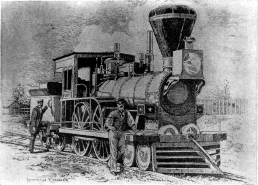 The Fury
The “Fury,” built for the Boston and Worcester Railroad in 1849 by Wilmarth. It was known as a “Shanghai” because of its great height.") The Holyhead and Chester Mails
The Holyhead and Chester Mails") The Mail Coach
The Mail Coach") The Mail's Meeting
The Mail's Meeting") The Result of Feather-Edging
The Result of Feather-Edging In 1830 all this had disappeared, and we find in Mr. Nasmyth's sketch a regular fire-box, such as is...") The Rocket 1830
The Rocket 1830
In 1830 all this had disappeared, and we find in Mr. Nasmyth's sketch a regular fire-box, such as is used to this moment. In one word, the Rocket of 1829 is different from the Rocket of 1830 in almost every conceivable respect; and we are driven perforce to the conclusion that the Rocket of 1829 never worked at all on the Liverpool and Manchester Railway; the engine of 1830 was an entirely new engine.") The Stage Coach
The Stage Coach Messrs. Forest and Son received a design and order for the construction of a steel boat 28 ft. long,...") The Steel Boat 'Advance'
The Steel Boat 'Advance'
Messrs. Forest and Son received a design and order for the construction of a steel boat 28 ft. long, 6 ft. beam, and 2 ft. 6 in. deep. It was to be built of Siemens steel galvanized, and divided into twelve sections, each weighing about 75 lbs. The fore and aft sections were to be decked and watertight, to give buoyancy in case of accident. The Tube") The Tube
The Tube
The Tube Already, anticipating war in the air, a fighting aeroplane has been evolved; and a machine of this t...") The Vickers
The Vickers
Already, anticipating war in the air, a fighting aeroplane has been evolved; and a machine of this type is shown in Figure. The body, in which pilot and gunner sit, is armoured lightly with plates which will resist the penetration of a bullet. Such armouring was found necessary after the use of aeroplanes in Tripoli and the Balkans. When flying unavoidably low in these campaigns, and when fired at from the ground, the wooden bodies of machines were pierced by shot, and in several instances their occupants wounded. A fighting aeroplane A. Machine-gun projecting from opening in bow B. Gunner’s position C. Pilot’s seat D.D. Side windows for observation E. Engine and propeller.