


") Construction of a Monoplane wing
Construction of a Monoplane wing (651 visites)") London Hackney Cab (Boulnois’ Patent)
London Hackney Cab (Boulnois’ Patent) A.A.—Main-planes; B. Double front elevator; C. Rudder (two narrow vertical planes); D. Motor; E. P...") The Wright Biplane
The Wright Biplane
A.A.—Main-planes; B. Double front elevator; C. Rudder (two narrow vertical planes); D. Motor; E. Propellers; F. Pilot’s lever; G. Skids upon which machine landed. It is now possible to describe, as a completed craft, the Wright power-driven plane; The picture shows its appearance; and in looking at it one is struck by the fact that, save for one or two modifications, and the fitting of motor and propellers, the machine is practically a glider, such as the Wrights used for soaring tests. Of the changes to be observed, the most interesting concern the elevator and rear-rudder. The former, it will be seen, has a double plane; it is, in fact, a smaller biplane on the principle of the main-planes. Needing to increase the surface of the elevator, the brothers fixed one plane above another so as to make the construction stronger and occupy less space. The rear-rudder, acting like that of a ship. In the launching of gliders, some French experimenters showed ingenuity. The brothers Voisin, for in...") Voisin Glider towed by a motor-car
Voisin Glider towed by a motor-car
In the launching of gliders, some French experimenters showed ingenuity. The brothers Voisin, for instance, who played a prominent part in the early tests in France, adopted the plan illustrated. The gilder was towed by a motor-car across an open stretch of ground; then, when its speed was sufficient for the planes to lift, it rose and flew behind the car like a kite. A ship that was built half a century too early. This huge vessel, built in 1857, was designed to mak...") The Great Eastern
The Great Eastern
A ship that was built half a century too early. This huge vessel, built in 1857, was designed to make the voyage from England to Australia without refuelling. She never made the voyage to Australia, but was used to lay the Atlantic cable. She was ahead of her time, for engines had not developed to the point where she could be properly propelled.") Sacramento Electric, Gas and Railway Co., Car 2
Sacramento Electric, Gas and Railway Co., Car 2 Once the value of aerial reconnaissance had been proved, France proceeded to the development of a sc...") Grahame-White Military Biplane - side view
Grahame-White Military Biplane - side view
Once the value of aerial reconnaissance had been proved, France proceeded to the development of a scouting aeroplane; and the need, in such a machine, is that the observer shall have a clear view ahead and below. The construction of machines was, for this reason, modified. The front elevating plane was moved to the rear, where it was fitted in the form of a flap—as in the case of monoplanes—and the pilot and observer placed in a covered-in body, which projected in front of the main-planes, as shown in the figure. By placing the body before the planes, the observer has a clear view ahead and on either side; and even when he leans over the side, and looks directly downward, there is no surface to obstruct him. A. Covered-in body, with seats for pilot and passenger B. Motor (to minimise wind resistance, only the lower cylinders are exposed to the air) C. Propeller D. Main-planes E. Rudder F. Elevator G. Landing gear.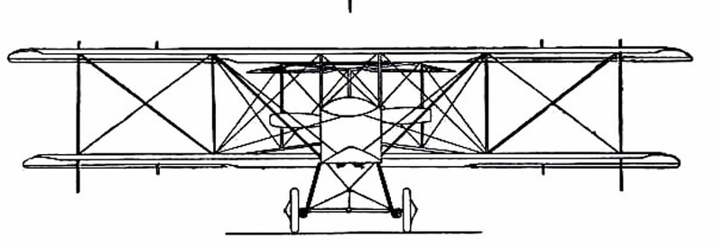
 (641 visites) Their first glider was a biplane, with 165 square feet of lifting surface, as illustrated in figure;...") The 1900 Wright Glider (operator’s position)
The 1900 Wright Glider (operator’s position)
Their first glider was a biplane, with 165 square feet of lifting surface, as illustrated in figure; several of its features need explanation. First there is the position of the operator; he can be seen lying prone across the centre of the lower plane. This attitude was adopted by the Wrights to minimise wind-pressure. Should a man be upright in his machine, they calculated that his body would, as the glider passed through the air, offer an appreciable resistance; while, in lying flat, he would offer scarcely any resistance at all. Of the doings of another of these brave but reckless men—a Saracen who tried to fly in the twelfth...") First attempts
First attempts
Of the doings of another of these brave but reckless men—a Saracen who tried to fly in the twelfth century—there is fuller information. He provided himself with wings which he stiffened with wooden rods, and held out upon either side of his body. Wearing these, he mounted to the top of a tower in Constantinople and stood waiting for a favourable gust of wind. When this came and caught his wings, he “rose into the air like a bird.” And then, of course, seeing that he had no idea of balancing himself when actually aloft, he fell pell-mell and “broke his bones.” People who had gathered to watch, seeing this inglorious ending to the flight, burst into laughter: ridicule rather than praise, indeed, was the fate of the pioneers, even to the days when the first real flights were made. Of the devices suggested [for man to fly] many showed ingenuity; and some were quaint, in view of ...") Besnier’s Apparatus
Besnier’s Apparatus
Of the devices suggested [for man to fly] many showed ingenuity; and some were quaint, in view of what we know of flight to-day. In the machine, for instance, designed by an experimenter named Besnier—who was a locksmith by trade—there were four lifting planes, closing on the up-stroke and opening on the down, and these the operator was to flap by the use of his hands and feet.") King George IV. in His Pony Phaeton
King George IV. in His Pony Phaeton Phillips built the strange-looking machine. It resembled, more than anything else, a huge Venetian b...") Phillips’s Experimental Craft
Phillips’s Experimental Craft
Phillips built the strange-looking machine. It resembled, more than anything else, a huge Venetian blind; and he adopted this form so as to introduce as many narrow planes as possible. There were, as a matter of fact, fifty in the machine, each 22 feet long and only 1½ inch wide. The craft, as can be seen, was mounted on a light carriage which, having wheels fitted to it, ran round and round upon a railed track. A steam engine was used as motive power, driving a two-bladed propeller at the rate of 400 revolutions a minute. The machine was so arranged on its metals that, although the rear wheels could raise themselves and show whether the planes exercised a lift, the front one was fixed to its track—thus preventing the apparatus from leaping into the air, overturning, and perhaps wrecking itself. Tests with the machine were successful. The lifting influence of the planes, when the engine drove them forward, was sufficient to raise the rear wheels from the track; and they did so even when a weight of 72 lbs., in addition to that of the apparatus, had been placed upon the carriage. In his main object, then, Phillips succeeded; and that was to show the lifting power of his planes. But his apparatus had not the makings of a practical aeroplane. He gained for himself, nevertheless, a name that has lived and will live.") Space Shuttle - forward and Adt elevations
Space Shuttle - forward and Adt elevations One of the men who thus laboured, without himself seeing his work brought to the goal of success, wa...") Langley’s Steam-driven Model
Langley’s Steam-driven Model
One of the men who thus laboured, without himself seeing his work brought to the goal of success, was Professor S. P. Langley, an American scientist connected with the Smithsonian Institution, and a man of original ideas and great resource. He made a methodical investigation of the action of lifting planes and the shape of propellers, using a large revolving table so that he could test the latter while they were moving through the air. Then he began building models which took a double monoplane form, as indicated in picture, with wings set at dihedral or upturned angle. This uptilting of the wings was to give the models stability while in flight: and the fixing of planes at the dihedral angle was tested, by later experimenters, in regard to full-sized machines.") Travelling Post, 1825-35
Travelling Post, 1825-35 Henson and Stringfellow built in 1845 a model which weighed about 30 lbs.; and although its stabilit...") Henson and Stringfellow’s Model
Henson and Stringfellow’s Model
Henson and Stringfellow built in 1845 a model which weighed about 30 lbs.; and although its stability was not perfect, it was an interesting machine—a forecast of the monoplane of the future. Here one saw the lifting planes take shape; the body between the wings; the tail-planes at the rear; and, above all, a suggestion of the means by which machines would be driven through the air: the fitting to the model, that is to say, of revolving propellers or screws. When an inventor has fitted an engine to an aircraft, means must be devised for using its power to drive the machine through the air; and to make the wings flap like those of a bird, has been found so complicated, owing to the mechanism necessary to imitate natural movements, that much of the power is wasted. Inventors such as Henson and Stringfellow, realising this difficulty, made wings that were outstretched and immovable, like those of a bird when it is soaring, and relied upon screw propellers—which they set spinning at great speed by means of their engines—to thrust their craft forward through the air. A method of flying was suggested as long ago as 1744, by the inventor De Bacqueville; his plan was ...") De Bacqueville
De Bacqueville
A method of flying was suggested as long ago as 1744, by the inventor De Bacqueville; his plan was to fix four planes or wings to his hands and feet, and then propel himself through the air by vigorous motions of his arms, and kickings of his legs. He made a flight from a balcony overlooking a river, but finished his trial ingloriously by falling into a barge. Such schemes, indeed, were doomed to failure; and they are only interesting because they show how, even in those far-off days, men were ready to risk their lives in attempts to conquer the air. Hence there is a type of fast scouting monoplane, in which a pilot can ascend alone, and fly at 100 ...") Single-seated Air Scout
Single-seated Air Scout
Hence there is a type of fast scouting monoplane, in which a pilot can ascend alone, and fly at 100 miles an hour. With such a craft, sweeping rapidly above an enemy’s position, the pilot-observer can return with his information at surprising speed. In the figure an air-scout of this type is seen. The tapering, covered-in body will be observed; this is to reduce wind resistance as the machine rushes through the air. The Gnome engine is, for the same reason, covered by an aluminium shield, which only allows the lower cylinders to project; they must, of course, be exposed in some way to the air, or they would not cool themselves. The landing-carriage has been reduced to its simplest form; this, again, is to reduce wind resistance; and the pilot, sitting deep in the body, shows only his head as the machine flies. Here, again, apart from the greater comfort in being so shielded, the placing of the pilot within the machine spells a lessening of pressure. A. Propeller B. Motor (partly hidden by shield) C. Pilot’s seat D. Sustaining plane E. Rudder F. Elevating-plane G. Chassis. The engines drove two canvas-covered wooden screws, each 18 feet in length, and the general appearan...") The Maxim Machine
The Maxim Machine
The engines drove two canvas-covered wooden screws, each 18 feet in length, and the general appearance of the machine is indicated by the picture. In these trials, although it was always captive, the aeroplane demonstrated much that its inventor had set himself to prove. In Sir Hiram Maxim’s own words, it showed that it had “a lifting effect of more than a ton, in addition to the weight of three men and 600 lbs. of water.” He adds: “My machine demonstrated one very important fact, and that was that very large aeroplanes had a fair degree of lifting power for their area.”, 1750 (612 visites)") Travelling Posting Carriage (2), 1750
Travelling Posting Carriage (2), 1750 One of the first to work upon Sir George Cayley’s theories was an experimenter
named Henson. H...") Henson's Proposed machine
Henson's Proposed machine
One of the first to work upon Sir George Cayley’s theories was an experimenter named Henson. He planned an ambitious machine weighing about a ton. It was to have planes of canvas stretched over a rigidly trussed frame of bamboo rods and hollow wooden spars; and these planes were to contain 4500 square feet of lifting surface, and be driven by screws operated by a steam engine of 30 h.p. But this craft did not take practical shape, although in its appearance and many of its details it bore a resemblance to machines which ultimately were to fly. In the specification of the patent he took out for his invention, Henson indicated that it was for “Improvements in locomotive apparatus and machinery for conveying letters, goods, and passengers from place to place through the air.” There is a type of aeroplane which will be carried to sea when a fleet sails, stowed in sections wit...") Launching sea-planes from a ship’s deck
Launching sea-planes from a ship’s deck
There is a type of aeroplane which will be carried to sea when a fleet sails, stowed in sections within the hull of a transport ship. This machine—a light, high-speed craft—will be assembled upon the deck of its parent ship, and launched into the air by special mechanism, as there is not room for a machine to run upon wheels, and leave the ship’s deck as it might do upon land; the vessel, besides, might be rolling in a high sea. In some cases a platform is built upon the deck, either at the bow or stern, and along this the aircraft moves, so as to gain speed for its planes to lift. In one device, seen in Figure, the machine is mounted upon a light wheeled cradle, and this is placed upon the starting-rail. Then, driven by its propeller, the plane runs forward upon the cradle till it reaches the end of the rail, when it glides into the air, the cradle falling from it and dropping into the sea, from which it is retrieved and drawn back on board the ship. The sea-plane (A.) is seen taking flight, having glided upon its cradle along the platform (B.). The cradle (C.) is just falling away below the aircraft’s hull. When the Wrights had built an engine, there was still the question how they should make it drive the...") Wright Motor and Propellers
Wright Motor and Propellers
When the Wrights had built an engine, there was still the question how they should make it drive their aeroplane. They inclined naturally to the idea of an aerial propeller. Two courses lay open to them; they could fit one propeller running at high speed and coupled directly to the motor, or they could use two propellers, revolving at slower speed and geared in some way to the engine. They decided upon the latter course, placing two propellers behind the main planes of their machine and driving them from the engine by means of light chains, these running in guiding tubes. This system of propulsion is shown. A. Motor; B. Gear-wheels upon motor crank-shaft; C.C. Tubes carrying driving chains; D.D. Sprocket-wheels over which chains pass; E.E. Propellers. Lilienthal was fascinated by the mechanism of the bird’s wing. He and his brother built one machin...") Lilienthal's Experiments
Lilienthal's Experiments
Lilienthal was fascinated by the mechanism of the bird’s wing. He and his brother built one machine after another to determine the exact amount of lifting effort that a man could obtain by imitating the wing-beat of a bird. One such apparatus is illustrated. This had a double set of wings; a wide pair in the centre and narrower ones in front and at the rear. These wings beat alternately, by movements of the operator’s legs; and the machine was suspended by a rope and pulleys from a beam, being counterbalanced by a weight. The tests showed this: that, after some practice in working the wings, a man could raise with them just half the weight of himself and of the machine; but the muscular effort proved so great that he could only maintain this rate of wing-beating for a few seconds. Here, incidentally, a fact may be mentioned: the energy a man can produce, at all events for a prolonged effort, has been estimated at about a quarter of a horse-power; and this—in tests so far made—has been insufficient for the purpose of wing-flapping flight.") Space Shuttle - isometric
Space Shuttle - isometric") Banked turn on a biplane
Banked turn on a biplane How lightly a petrol engine can be made was demonstrated by the firm constructing the Antoinette mo...") Man lifting a 100 horse-power aeroplane motor
Man lifting a 100 horse-power aeroplane motor
How lightly a petrol engine can be made was demonstrated by the firm constructing the Antoinette motor, with which many of the pioneers fitted their craft. A 16-cylinder engine was made so that a man could raise it upon his shoulders—as shown in Figure —and carry it without much difficulty; and yet this same motor, which one man could lift from the ground, developed 100 horse-power. A. Enclosed body
B. Driver’s position
C. Steering wheel
D. Foot-controlled throttle lever for e...") The single-seated 'air-car'—a suggested type
The single-seated 'air-car'—a suggested type
A. Enclosed body B. Driver’s position C. Steering wheel D. Foot-controlled throttle lever for engine E.E. The two sustaining-planes F. The motor G. Propeller H. Rudder I. Elevating-plane J. Landing gear. First probably for mails, and after this for passenger-carrying, will aeroplanes of the future be employed; and they will find a scientific use, too, in exploring remote corners of the earth, and in passing above forests which are now impenetrable. Small, fast machines, much cheaper than those of to-day, will be bought also for private use—many of them, as suggested by the figure, having room for only one man within their hulls. Then there will be flying clubs; and to these, after their day’s work, will come a city’s toilers. Through the cheapening of craft, as time goes on, practically all members of the community will experience the joys of flight. Thus, say on a summer’s evening, the doors of the sheds will be pushed aside, and the machines wheeled out and overhauled; then, one by one, these small, fast-moving craft will rise into the air and dart here and there—circling, manœuvring, dipping, and diving.") Space Shuttle - port elevation
Space Shuttle - port elevation") Driving-seat of a touring plane
Driving-seat of a touring plane The fitting of several motors has been shown to be practical; and it has the obvious advantage that,...") Multiple-engined craft
Multiple-engined craft
The fitting of several motors has been shown to be practical; and it has the obvious advantage that, should one fail while in the air, the other or others will maintain a craft in flight. In such a machine as would fly the Atlantic, for example, it is proposed to fit four motors developing 800 h.p., and to carry a couple of mechanics who would constantly be tending them. Thus, should one engine develop trouble, its repair could be effected without descent, and with no worse result than a temporary fall in speed. In the figure is shown a method by which three Gnome motors may be fitted to a biplane. A. First engine (a 50-h.p. Gnome) B. Second engine (which is on the same shaft, but will run independently) C. Third Gnome engine, also an independent unit D. Four-bladed propeller (mounted higher than the crank-shaft bearing the engines, and driven by a chain gearing).") A type of extemporised motor ambulance favoured by the French and Belgians
A type of extemporised motor ambulance favoured by the French and Belgians") A 'Fischer' Combination Omnibus
A 'Fischer' Combination Omnibus This ship may be said to be the first of the transatlantic liners,
for in her, for the first time,...") The Steamship Oceanic
The Steamship Oceanic
This ship may be said to be the first of the transatlantic liners, for in her, for the first time, great concessions were made for the comfort and convenience of the passengers. Biplane (537 visites) A. Hull, which is steel-built, containing pilot and passenger
B. Main-planes—the lower at a dihed...") D.F.W. (German-designed) Biplane
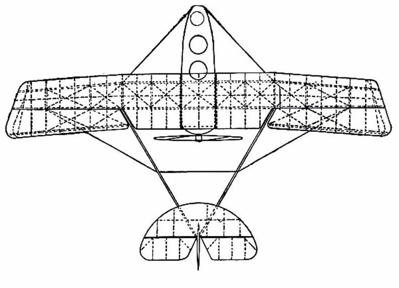
D.F.W. (German-designed) Biplane
A. Hull, which is steel-built, containing pilot and passenger B. Main-planes—the lower at a dihedral angle C. Uptilted stabilising ailerons, which may be locked in position D. Stabilising fin E. Rudder F. Elevating-plane G. 100-h.p. motor (which is enclosed) and propeller.") Royal Mail Coach
Royal Mail Coach An awkward and unsuccessful ship.
She proved, however, when she was wrecked, that for ship constru...") The Great Britain
The Great Britain
An awkward and unsuccessful ship. She proved, however, when she was wrecked, that for ship construction iron is stronger than wood, and proved, too, that double bottoms, bulkheads, and bilge keels, which were new departures when she was built, were most desirable in ships of her size. The greatest clipper ship ever built. Unfortunately, before she made her first voyage she caught fir...") The Great Republic
The Great Republic
The greatest clipper ship ever built. Unfortunately, before she made her first voyage she caught fire and had to be sunk. She was refloated and refitted, but never made a voyage in her original rig. When new masts were put in her they were made smaller than the first ones. Still she turned out to be one of the very fastest of the clippers. Which, with the Fiery Cross, Taeping, Serica, and Taitsing, sailed what was, perhaps, the greatest r...") The Ariel, 1866
The Ariel, 1866
Which, with the Fiery Cross, Taeping, Serica, and Taitsing, sailed what was, perhaps, the greatest race ever run. After sailing 16,000 miles from Foo-Chow, China, to London, the Ariel, Taeping, and Serica docked in London on the same tide, the Taeping the winner by only a few minutes. The other two were only two days behind, although the first three took 99 days. Square-rigged ships have largely disappeared because, among other things, their crews were large.
T...") An American Coasting Schooner
An American Coasting Schooner
Square-rigged ships have largely disappeared because, among other things, their crews were large. These schooners, which sometimes have four or five masts, can be handled by small crews and consequently are able to continue to vie with steam. This ship shows the new sail plan overcoming the old. The masts carry topsails,
topgallantsails, a...") A Corvette of 1780
A Corvette of 1780
This ship shows the new sail plan overcoming the old. The masts carry topsails, topgallantsails, and royals, and what was formerly a lateen sail on the mizzenmast has become a spanker. Furthermore, while the ship carries jibs, she has not yet parted with her spritsails. A British warship of 1654. This ship is an excellent example of the ships that were in use just befo...") The Amaranthe
The Amaranthe
A British warship of 1654. This ship is an excellent example of the ships that were in use just before the jib began to put in its appearance. The lateen sail on the mizzenmast is similar to the one used on the caravels, but both the rigging and the hull are greatly refined as compared with the ships of the time of Columbus. It was on boats of this type that the jib seems first to have been used. To-day in Holland one sees ...") A 16th-Century Dutch Boat
A 16th-Century Dutch Boat
It was on boats of this type that the jib seems first to have been used. To-day in Holland one sees a similar boat, called a schuyl, which is almost identical with this, except that it utilizes a curved gaff at the top of the mainsail.") The American Frigate Constitution
The American Frigate Constitution With a lookout at the masthead these ships cruised all over the earth in the first half of the 19th ...") A Whaling Bark
A Whaling Bark
With a lookout at the masthead these ships cruised all over the earth in the first half of the 19th Century.") A Few Types of Sailing Ships Common in European and American Waters
A Few Types of Sailing Ships Common in European and American Waters By the time this ship was built hulls had grown considerably in size over what they had been at the ...") An English Warship of the Time of Henry V
An English Warship of the Time of Henry V
By the time this ship was built hulls had grown considerably in size over what they had been at the time of William the Conqueror, and the era of lavish decoration was well under way. The numerous decks of this ship were not unusual for the time. The first completely successful steamboat ever built. Others built before the Clermont were made to ...") Robert Fulton’s Clermont
Robert Fulton’s Clermont
The first completely successful steamboat ever built. Others built before the Clermont were made to go, but this ship carried passengers for years. Such schooners as this are common in the New England fishing fleets. They are seaworthy and fast, an...") A Gloucester Fisherman
A Gloucester Fisherman
Such schooners as this are common in the New England fishing fleets. They are seaworthy and fast, and probably the men who sail them are the greatest seamen of our time. A cargo liner is a freight ship that sails on scheduled dates and routes, and is different in this f...") A Cargo Liner
A Cargo Liner
A cargo liner is a freight ship that sails on scheduled dates and routes, and is different in this from a “tramp” which takes what cargoes it can at any time and to any port. These merchant ships, which sailed from England to the Far East, were almost as much like warships a...") A British East Indiaman
A British East Indiaman
These merchant ships, which sailed from England to the Far East, were almost as much like warships as they were like merchantmen. They were finely built, but they took their time on their voyages out and back. Formerly the German liner Vaterland, and taken over by the United States during the World War.") The Leviathan
The Leviathan
Formerly the German liner Vaterland, and taken over by the United States during the World War. These steamers are often seen in European waters and are widely used as excursion boats.") A European Side-wheeler
A European Side-wheeler
These steamers are often seen in European waters and are widely used as excursion boats. Formerly the German liner Bismarck. It is now the property of the White Star Line.") The Majestic
The Majestic
Formerly the German liner Bismarck. It is now the property of the White Star Line. One of the seven wonders of the ancient world, and one of the first great lighthouses.") The Pharos at Alexandria
The Pharos at Alexandria
One of the seven wonders of the ancient world, and one of the first great lighthouses. A British liner belonging to the White Star Line.") The Homeric
The Homeric
A British liner belonging to the White Star Line. This awkward ship is one of the type that made up the great fleets that fought, for instance, at Tra...") A British Line-of-Battle Ship, 1790
A British Line-of-Battle Ship, 1790
This awkward ship is one of the type that made up the great fleets that fought, for instance, at Trafalgar. Nelson’s flagship, the Victory, is of this type. The overhanging bow and stern were common on most early Egyptian ships, and the heavy cable, stretch...") A Large Egyptian Ship of the 18th Dynasty
A Large Egyptian Ship of the 18th Dynasty
The overhanging bow and stern were common on most early Egyptian ships, and the heavy cable, stretched from one end of the hull to the other and supported on two crutches, was used to strengthen these overhanging ends. And a ship undergoing repairs.") A Floating Dry Dock
A Floating Dry Dock
And a ship undergoing repairs. In which Captain Joshua Slocum circumnavigated the globe.") The Spray
The Spray
In which Captain Joshua Slocum circumnavigated the globe.