


 One interesting outcome of his numerous experiments was the Hargrave Kite, now more familiarly known...") Hargrave’s kite
Hargrave’s kite
One interesting outcome of his numerous experiments was the Hargrave Kite, now more familiarly known as the box kite. A good example of his kites is the type shown. This consists of two arched biplanes mounted tandem on a backbone, or connecting framework. The kite floats steadily, and was thought suitable for the body of a flying machine to be driven by an engine and propeller. Thus meteorology is indebted to aëronautics for its most useful kite. Supposed to have been in use in England about
A.D.. 1100-1200.
Strutt states that the chariot ...") Hammock Waggon
Hammock Waggon
Supposed to have been in use in England about A.D.. 1100-1200. Strutt states that the chariot of the Anglo-Saxons was used by distinguished persons for travel. If the illustrations from which he describes them give a fair idea of their proportions and general construction, they must have been singularly uncomfortable conveyances. The drawing is taken from an illuminated manuscript of the Book of Genesis in the Cotton Library (Claud. B. iv.), which Strutt refers to the ninth century, but which a later authority considers a production of the earlier part of the eleventh. The original drawing shows a figure in the hammock waggon, which figure represents Joseph on his way to meet Jacob on the latter’s arrival in Egypt; this figure has been erased in order to give a clear view of the conveyance, which no doubt correctly represents a travelling carriage of the artist’s own time, viz., a.d. 1100-1200. Excessive number of Coaches in London.
The preamble of a patent granted Sir Saunders Duncombe in ...") Hackney Coaches in London, 1637
Hackney Coaches in London, 1637
Excessive number of Coaches in London. The preamble of a patent granted Sir Saunders Duncombe in 1634 to let Sedan chairs refers to the fact that the streets of London and Westminster “are of late time so much encumbered and pestered with the unnecessary multitude of coaches therein used”; and in 1635 Charles I. issued a proclamation on the subject. This document states that the “general and promiscuous use” of hackney coaches in great numbers causes “disturbance” to the King and Queen personally, to the nobility and others of place and degree; “pesters” the streets, breaks up the pavements and cause increase in the prices of forage. For which reasons the use of hackney coaches in London and Westminster and the suburbs is forbidden altogether, unless the passenger is making a journey of at least three miles. Within the city limits only private coaches were allowed to ply, and the owner of a coach was required to keep four good horses or geldings for the king’s service. The first all-big-gun ship, and the one that gave its name to present-day battleships, which are uni...") H. M. S. Dreadnaught
H. M. S. Dreadnaught
The first all-big-gun ship, and the one that gave its name to present-day battleships, which are universally called dreadnaughts or super-dreadnaughts. Grumman OA-9
Front Side
...") Grumman OA-9
Grumman OA-9
Grumman OA-9 Front Side Perspective Bottom Top") Group of French Aviators
Group of French Aviators The Gross III measured 70 meters long, cubed 7,500 meters, and was propelled by four Körting motors...") Gross III
Gross III
The Gross III measured 70 meters long, cubed 7,500 meters, and was propelled by four Körting motors aggregating 300 horse power. This was a splendid vessel, and one of extraordinary speed. Once the value of aerial reconnaissance had been proved, France proceeded to the development of a sc...") Grahame-White Military Biplane - side view
Grahame-White Military Biplane - side view
Once the value of aerial reconnaissance had been proved, France proceeded to the development of a scouting aeroplane; and the need, in such a machine, is that the observer shall have a clear view ahead and below. The construction of machines was, for this reason, modified. The front elevating plane was moved to the rear, where it was fitted in the form of a flap—as in the case of monoplanes—and the pilot and observer placed in a covered-in body, which projected in front of the main-planes, as shown in the figure. By placing the body before the planes, the observer has a clear view ahead and on either side; and even when he leans over the side, and looks directly downward, there is no surface to obstruct him. A. Covered-in body, with seats for pilot and passenger B. Motor (to minimise wind resistance, only the lower cylinders are exposed to the air) C. Propeller D. Main-planes E. Rudder F. Elevator G. Landing gear.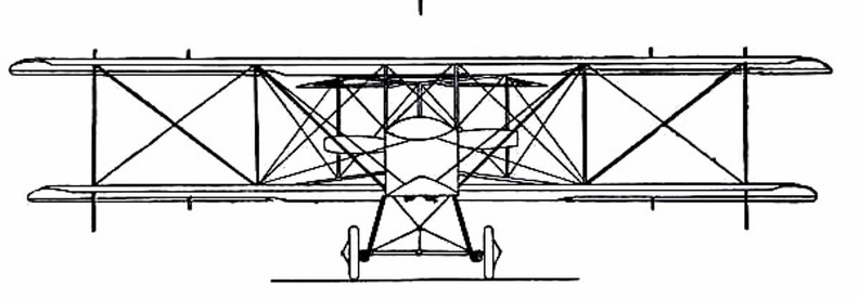
 showing the position of the body and the construction of the landing gear.") Grahame-White Military Biplane - front view
Grahame-White Military Biplane - front view
showing the position of the body and the construction of the landing gear.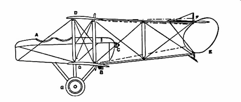
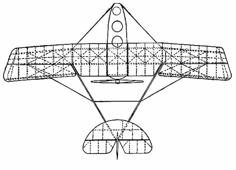
 showing shape and spread of planes and tail, and position of pilot and passenger.") Grahame-White Military Biplane
Grahame-White Military Biplane
showing shape and spread of planes and tail, and position of pilot and passenger.
 From Engraving, A.D. 1750.") Going to Bury Fair
Going to Bury Fair
From Engraving, A.D. 1750. Parseval Kite Balloon.
Another valiant English leader in aërostation was James Glaisher, member ...") Glaisher and Coxwell
Glaisher and Coxwell
Parseval Kite Balloon. Another valiant English leader in aërostation was James Glaisher, member of the British Association for the Advancement of Science. As one of a committee of twelve appointed by that body in 1861, to explore the higher strata of the atmosphere by means of the balloon, he volunteered his services as an observer, when no other capable man could offer to do so. With a professional aëronaut, Mr. Coxwell, and a new balloon specially constructed for the work, cubing 90,000 feet, he made eleven ascensions for the society, four from Wolverhampton, seven from Woolwich. Incidentally he made seventeen other ascents of various altitude; not at the expense of the committee, but as a scientific passenger in public balloon ascents advertised beforehand. The illustrious Henri Giffard was perhaps the first aëronautical engineer adequately endowed and ci...") Giffard’s steam dirigible, 1852
Giffard’s steam dirigible, 1852
The illustrious Henri Giffard was perhaps the first aëronautical engineer adequately endowed and circumstanced to realize, on a practical scale, General Meusnier’s well pondered and truly scientific plans for a motor balloon. He had studied in the college of Bourbon, and had worked in the railroad shops of the Paris and St. Germain railway. He had further equipped himself by making free balloon ascensions, under the auspices of Eugene Godard, for the purpose of studying the atmosphere; and by building light engines, one of which weighed 100 pounds, and developed three horse power. Finally in 1851 he patented an air ship, consisting of an elongated bag and car, propelled by a screw driven by a steam engine. He had not the means to build such a vessel, but he had the genius and training necessary to construct it, and at the same time enough enthusiasm and persuasive power to induce his friends, David and Sciama, to loan him the requisite funds. While Blanchard and other aëronauts were paddling their globose bags in search of favorable winds, ...") General Meusnier’s proposed dirigible, 1784
General Meusnier’s proposed dirigible, 1784
While Blanchard and other aëronauts were paddling their globose bags in search of favorable winds, vainly hoping thereby to direct their course in the air, General Meusnier of the French army, and member of the Academy of Sciences, made a systematic study of the requirements for practical air navigation. After some research on forms suitable for aëronautic hulls, he designed a power balloon having a pointed car suspended from a bag of goose-egg form, this latter embodying his idea of the best shape for a balloon that must cleave the air swiftly and resist deformation. The propulsion was to be effected by means of three coaxial screw propellers, supported on the rigging between car and bag, and actuated by eighty men, for lack of a light artificial motor. He thus hoped to obtain a moderate velocity which, combined with skillfully selected air currents, would enable the ship to reach her destination in ordinary weather “In the accompanying figure the solid arrows in the interior part represent the resultant motions ...") General circulation of the atmosphere
General circulation of the atmosphere
“In the accompanying figure the solid arrows in the interior part represent the resultant motions of the winds (longer arrows indicating greater velocities), in case of an earth with a homogeneous surface over both hemispheres, in which the motions would be symmetrical in both and the same at all longitudes, and the equatorial and tropical calm belts would be situated at equal distances from each pole. The dotted arrows indicate the strong, almost eastern motion of the air at all latitudes at some high altitude, as that of the cirrus clouds. Gearless, 75 H.P. Gearless Transmission Co., Rochester, N. Y.
PRICE: $3,750
BODY: Side entr...") Gearless, 75 H.P
Gearless, 75 H.P
Gearless, 75 H.P. Gearless Transmission Co., Rochester, N. Y. PRICE: $3,750 BODY: Side entrance tonneau SEATS: 7 persons WEIGHT: 3,000 pounds WHEEL-BASE: 128 inches TREAD: 56 inches TIRES, FRONT: 36 × 4 inches TIRES, REAR: 36 × 4½ inches STEERING: Worm and nut BRAKES: On transmission and 2 on each rear hub SPRINGS: Semi-elliptical FRAME: Pressed steel BORE: 413/16 in.; STROKE: 5⅝ in. CYLINDERS: 6 vertical in front VALVE ARRANGEMENT: Inlet and exhaust in side ports MOTOR SUSPENSION: From sub-frame COOLING: Water IGNITION: Jump spark, 2 sets of plugs CURRENT SUPPLY: Storage battery and magneto CARBURETER: Float-feed LUBRICATION: Pump driven by gears MOTOR-CONTROL: Spark and throttle CLUTCH: Expanding ring CHANGE GEAR: Gearless 1907 model, direct drive SPEEDS: 2 forward and reverse CHANGE-GEAR CONTROL: Foot pedal for forward speeds; side lever for back up DRIVE: Shaft Gearless, 60 H.P. Gearless Transmission Co., Rochester, N. Y.
PRICE: $3,250
BODY: Side entr...") Gearless, 60 H.P
Gearless, 60 H.P
Gearless, 60 H.P. Gearless Transmission Co., Rochester, N. Y. PRICE: $3,250 BODY: Side entrance tonneau SEATS: 5 persons WEIGHT: 2,800 pounds WHEEL-BASE: 124 inches TREAD: 56 inches TIRES, FRONT: 36 × 4 inches TIRES, REAR: 36 × 4 inches STEERING: Worm and nut BRAKES: On transmission and rear hubs SPRINGS: Semi-elliptical FRAME: Pressed steel BORE: 5 in.; STROKE: 5 in. CYLINDERS: 4 vertical in front, 2 cycle MOTOR SUSPENSION: From sub-frame COOLING: Water IGNITION: Double jump spark CURRENT SUPPLY: Magneto and battery CARBURETER: Float-feed LUBRICATION: Mechanical force feed MOTOR-CONTROL: Spark and throttle CLUTCH: Expanding ring CHANGE GEAR: Gearless direct drive SPEEDS: 2 forward and reverse CHANGE-GEAR CONTROL: Side lever and foot pedal DRIVE: Shaft Gearless, 50 H.P. Gearless Transmission Co., Rochester, N. Y.
PRICE: $3,000
BODY: Side entr...") Gearless, 50 H.P
Gearless, 50 H.P
Gearless, 50 H.P. Gearless Transmission Co., Rochester, N. Y. PRICE: $3,000 BODY: Side entrance tonneau SEATS: 5 persons WEIGHT: 2,600 pounds WHEEL-BASE: 124 inches TREAD: 56 inches TIRES, FRONT: 36 × 4 inches TIRES, REAR: 36 × 4 inches STEERING: Worm and nut BRAKES: On transmission and two on each rear hub SPRINGS: Semi-elliptical FRAME: Pressed steel BORE: 4⅝ in.; STROKE: 5 in. CYLINDERS: 4, vertical in front; two cycle MOTOR SUSPENSION: From sub-frame COOLING: Air jackets. Blower; copper fins cast on cylinders IGNITION: Jump spark CURRENT SUPPLY: Storage battery and dry cells CARBURETER: Float-feed LUBRICATION: Mechanical force feed oiler MOTOR-CONTROL: Spark and throttle CLUTCH: Expanding ring CHANGE GEAR: Gearless 1907 model, direct drive SPEEDS: 2 forward and reverse CHANGE-GEAR CONTROL: Foot pedal for forward speeds; ride lever for reverse DRIVE: Shaft The Clermont made her first voyage from New York to Albany, August 7th, 1807.
Her speed was about ...") Fulton’s ‘Clermont’ on The Hudson, 1807
Fulton’s ‘Clermont’ on The Hudson, 1807
The Clermont made her first voyage from New York to Albany, August 7th, 1807. Her speed was about five miles an hour. During the winter of 1807-8 she was enlarged, her name being then changed to North River. She continued to ply successfully on the Hudson as a passenger boat for a number of years, her owners having acquired the exclusive right to navigate the waters of the State of New York by steam. Frontenac, Model C, 40 H.P. Abendroth & Root Mfg. Co., Newburgh, N. Y.
PRICE: $3,500
BODY: ...") Frontenac, Model C, 40 H.P
Frontenac, Model C, 40 H.P
Frontenac, Model C, 40 H.P. Abendroth & Root Mfg. Co., Newburgh, N. Y. PRICE: $3,500 BODY: Side entrance tonneau SEATS: 5 to 7 persons WEIGHT: 2,800 pounds WHEEL-BASE: 123 inches TREAD: 56 inches TIRES, FRONT: 34 × 4 inches TIRES, REAR: 34 × 4½ inches STEERING: Bevel gear connecting to worm and nut BRAKES: Internal and external on rear wheels BORE: 4¾ in.; STROKE: 5 in. SPRINGS: Semi-elliptical FRAME: Pressed steel CYLINDERS: 4, vertical in pairs VALVE ARRANGEMENT: On same side MOTOR SUSPENSION: From sub-frame COOLING: Water, fin tube radiator IGNITION: Jump spark CURRENT SUPPLY: Storage battery and magneto CARBURETER: Automatic LUBRICATION: Splash MOTOR-CONTROL: Spark and throttle CHANGE GEAR: Sliding type SPEEDS: 3 forward and reverse CHANGE-GEAR CONTROL: Selective system DRIVE: Shaft Frontenac Runabout, Model D, 40–45 H.P. Abendroth and Root M'f'g. Co., Newburgh, N. Y.
PRI...") Frontenac Runabout, Model D, 40–45 H.P
Frontenac Runabout, Model D, 40–45 H.P
Frontenac Runabout, Model D, 40–45 H.P. Abendroth and Root M'f'g. Co., Newburgh, N. Y. PRICE: $3,500 BODY: Runabout SEATS: 3 persons WEIGHT: 2,500 pounds WHEEL-BASE: 123 inches TREAD: 56 inches TIRES, FRONT: 36 × 3½ in. TIRES, REAR: 36 × 4½ in. STEERING: Bevel gear and shaft connecting to worm and nut BRAKES: External and internal on rear wheels SPRINGS: Semi-elliptical FRAME: Pressed steel BORE: 4¾ in.; STROKE: 5 in. CYLINDERS: 4 vertical, in pairs VALVE ARRANGEMENT: On one side MOTOR SUSPENSION: Sub-frame COOLING: Water; fin tube radiator IGNITION: Jump spark (double) CURRENT SUPPLY: Magneto and battery CARBURETER: Automatic float-feed LUBRICATION: Splash MOTOR-CONTROL: Spark and throttle CHANGE GEAR: Sliding type SPEEDS: 3 forward and reverse CHANGE-GEAR CONTROL: Selective system DRIVE: Shaft A still more ambitious helicopter was that shown invented by Professor Forlanini, an Italian Civil E...") Forlanini’s helicopter, 1878
Forlanini’s helicopter, 1878
A still more ambitious helicopter was that shown invented by Professor Forlanini, an Italian Civil Engineer, and launched in 1878. The lower screw was fastened to the frame of a steam engine, the upper screw was attached to the crank shaft. Steam was supplied from the globe shown beneath, which was two thirds filled with water, and well heated over a separate fire just before an ascension. As the globe was merely a reservoir of hot water and steam, carrying neither fuel nor furnace, its power waned rapidly. The best flight lasted about twenty seconds, attaining a height of 42 feet. The apparatus weighed 77 pounds, spread 21.5 square feet of screw surface, and lifted about 26.4 pounds per horse power.") Folsom Power House
Folsom Power House HEMMING'S UNICYCLE, or \"FLYING YANKEE VELOCIPEDE.\"
The single-wheeled velocipede has at length ...") Flying Yankee Velocipede
Flying Yankee Velocipede
HEMMING'S UNICYCLE, or "FLYING YANKEE VELOCIPEDE." The single-wheeled velocipede has at length received a palpable body, and " a local habitation and a name." Richard C. Hemming of New Haven, Conn., invented the machine herewith represented, two years ago; but has only recently brought it into the market and applied it to practical purposes.. The main wheel has a double rim, or has two concentric rims, the inner face of the inner one having a projecting lip for keeping the friction rollers and the friction driver in place; each of these being correspondingly grooved on their peripheries. The frame on which the rider sits, sustains these friction wheels in double parallel arms, on the front one of which is mounted a double pulley, with belts passing to small pulleys on the axis of the driving wheel. This double wheel driven, as seen, by cranks turned by the hands. The friction of the lower wheel on the surface of the inner rim of the main wheel is the immediate means of propulsion. A small binding wheel, seen between the rider's legs, serves to keep the bands or belts tight. The steering is effected either by inclining the body to one side or the other, or by the foot impinging on the ground, the stirrups being hung low for this purpose. By throwing the weight on these stirrups, the binding wheel may be brought more powerfully down on the belts. Over the rider's head is an awning, and there is also a shield in front of his body to keep the clothes from being soiled by mud and wet. When going forward, the driving wheel is kept slightly forward of the centre of gravity by the position of the rider. By this means the power exerted is comparatively small. Every turn of the crank is equivalent to a rotation of the great wheel. Mr. Hemming says that this machine can be manufactured for fifty dollars, of a weight of only thirty pounds;- that it will ascend steep grades, and that it can be driven on the roads with but little exertion, at the rate of twenty or even twenty-five miles an hour. This wheel is of a diameter of from six to eight feet. Mr. Hemming's boy of thirteen has one five feet in diameter, the first manufactured, crude in construction, and heavier than necessary, which he propels at the rate of a mile in three minutes. Carriage used about 1300-1350 in Flanders.
Carriages were in use on the continent long before they ...") Flight of Princess Ermengarde
Flight of Princess Ermengarde
Carriage used about 1300-1350 in Flanders. Carriages were in use on the continent long before they were employed in England. In 1294, Philip the Fair of France issued an edict whose aim was the suppression of luxury; under this ordinance the wives of citizens were forbidden to use carriages, and the prohibition appears to have been rigorously enforced. They were used in Flanders during the first half of the fourteenth century; an ancient Flemish chronicle in the British Museum (Royal MSS. 16,[9] F. III.) contains a picture of the flight of Ermengarde, wife of Salvard, Lord of Rouissillon. A favorite trick of the slaver, fleeing from a man-of-war, was to throw over slaves a few at a time ...") Fleeing Slaver
Fleeing Slaver
A favorite trick of the slaver, fleeing from a man-of-war, was to throw over slaves a few at a time in the hope that the humanity of the pursuers would impel them to stop and rescue the struggling negroes, thus giving the slave-ship a better chance of escape. Sometimes these hapless blacks thus thrown out, as legend has it Siberian peasants sometimes throw out their children as ransom to pursuing wolves, were furnished with spars or barrels to keep them afloat until the pursuer should come up; and occasionally they were even set adrift by boat-loads. It was hard on the men of the navy to steel their hearts to the cries of these castaways as the ship sped by them; but if the great evil was to be broken up it could not be by rescuing here and there a slave, but by capturing and punishing the traders. First flight engine, 1903, cross section") First flight engine, 1903, cross section
First flight engine, 1903, cross section
First flight engine, 1903, cross section First flight engine, 1903, assembly") First flight engine, 1903, assembly
First flight engine, 1903, assembly
First flight engine, 1903, assembly First flight engine, 1903 rear view") First flight engine, 1903 rear view
First flight engine, 1903 rear view
First flight engine, 1903 rear view First flight engine, 1903") First flight engine, 1903
First flight engine, 1903
First flight engine, 1903 Of the doings of another of these brave but reckless men—a Saracen who tried to fly in the twelfth...") First attempts
First attempts
Of the doings of another of these brave but reckless men—a Saracen who tried to fly in the twelfth century—there is fuller information. He provided himself with wings which he stiffened with wooden rods, and held out upon either side of his body. Wearing these, he mounted to the top of a tower in Constantinople and stood waiting for a favourable gust of wind. When this came and caught his wings, he “rose into the air like a bird.” And then, of course, seeing that he had no idea of balancing himself when actually aloft, he fell pell-mell and “broke his bones.” People who had gathered to watch, seeing this inglorious ending to the flight, burst into laughter: ridicule rather than praise, indeed, was the fate of the pioneers, even to the days when the first real flights were made. This lightship is anchored off Fire Island, near the southern coast of Long Island, U. S. A. Lightsh...") Fire Island Lightship
Fire Island Lightship
This lightship is anchored off Fire Island, near the southern coast of Long Island, U. S. A. Lightships sometimes mark shoals, and sometimes mark the entrances to harbours. They are always kept anchored in given spots and are merely floating lighthouses, although, of course, they are sometimes relieved by other lightships so that they may undergo repairs. Fighting Zeppelin raiders") Fighting Zeppelin raiders
Fighting Zeppelin raiders
Fighting Zeppelin raiders Fast mail-carrying aeroplanes will make postal deliveries everywhere") Fast mail-carrying aeroplanes will make postal deliveries everywhere
Fast mail-carrying aeroplanes will make postal deliveries everywhere
Fast mail-carrying aeroplanes will make postal deliveries everywhere Fairchild PT-19
Front Side...") Fairchild PT-19
Fairchild PT-19
Fairchild PT-19 Front Side Perspective Bottom Top We present an engraving of an English one-wheeled velocipede. The feet are placed on short stilts, c...") English one-wheeled Velocipede
English one-wheeled Velocipede
We present an engraving of an English one-wheeled velocipede. The feet are placed on short stilts, connected with the cranks, one on either side of the rim, while the rider sits upon a steel spring saddle over the whole wheel. The inventor modestly limits the diameter of the wheel to twelve feet, and the number of revolutions to fifty per minute. Twenty-five miles per hour is the speed expected to be reached. The riders of this machine, without the ability to overcome the laws of gravity, would be very likely to get broken bones and noses. It is not likely to come into general use.") Elevated Railroad Station
Elevated Railroad Station") Elevated Double Track Georgia Pine Structure
Elevated Double Track Georgia Pine Structure Electrical Power House (the largest in the Old World), Lot’s Road, Chelsea, to supply the Metropol...") Electrical Power House
Electrical Power House
Electrical Power House (the largest in the Old World), Lot’s Road, Chelsea, to supply the Metropolitan District and other Railways with Current A typical craft, representing the first of those navigated with any certainty, is shown in Figure. A...") Early-type Airship
Early-type Airship
A typical craft, representing the first of those navigated with any certainty, is shown in Figure. A gas-containing envelope, made of a light, strong, varnished fabric, is kept taut by the pressure of the gas within; the car, constructed of wood or metal tubing, is suspended by ropes from the envelope, and contains engine and crew, with a two-bladed propeller revolving astern. Such a machine, in its control, had an elevating-plane and rudder, upon the same principle as those of the aeroplane. One of the difficulties to be overcome was the expansion and contraction of gas in the envelope owing to differences in altitude and temperature. When the craft ascended, its envelope completely inflated, the gas began to dilate owing to the outer air becoming less dense; and some had to be allowed to escape through automatic valves. Then, should the machine descend to a lower level, there was not sufficient gas in the envelope to keep it tightly stretched, and it tended to sag at the bow as it was driven through the air. A. Gas envelope B. Car suspended below envelope C. Motor, which drives propeller (D) through a shaft E. Small horizontal plane for rising or descending F. Fixed fin, or keel plane, to give stability G. Rudder. Early type of Smack
For the fisheries a multitude of smaller types were constructed—such as the...") Early type of Smack
Early type of Smack
Early type of Smack For the fisheries a multitude of smaller types were constructed—such as the lugger, the shallop, the sharpie, the bug-eye, the smack. Description of first trip in the car
When I got this car ready to run one night, I took it out a...") Duryea Automobile
Duryea Automobile
Description of first trip in the car When I got this car ready to run one night, I took it out and I had a young fellow with me; I thought I might need him to help push in case the car didn't work…. We ran from the area of the shop where it was built down on Taylor Street. We started out and ran up Worthington Street hill, on top of what you might call "the Bluff" in Springfield. Then we drove along over level roads from there to the home of Mr. Markham , and there we refilled this tank with water. [At this point he was asked if it was pretty well emptied by then.] Yes, I said in my account of it that when we got up there the water was boiling furiously. Well, no doubt it was. We refilled it and then we turned it back and drove down along the Central Street hill and along Maple, crossed into State Street, dropped down to Dwight, went west along Dwight to the vicinity where we had a shed that we could put the car in for the night. During that trip we had run, I think, just about six miles, maybe a little bit more. That was the first trip with this vehicle. It was the first trip of anything more than a few hundred yards that the car had ever made. Giffard was succeeded in France, first by Dupuy de Lome; then by Gaston Tissandier, well-meaning pro...") Dupuy de Lome’s dirigible, 1872
Dupuy de Lome’s dirigible, 1872
Giffard was succeeded in France, first by Dupuy de Lome; then by Gaston Tissandier, well-meaning projectors of steerable balloons, but too cautious to effect an important advance in the art. The first of these gentlemen, an eminent marine engineer, in 1872, completed a gas balloon for the French government, resembling the one designed by General Meusnier in 1784, and like that also driven by muscular power actuating a screw, and kept rigidly inflated by use of an internal balloon, or ballonet. The car was suspended from the bag by a close fitting cover instead of a net, in order to lessen the resistance, and it was kept in alignment by use of crossed suspension cords. A speed of but six miles an hour was attained by the industrious work of eight men operating an ample screw propeller. A decade later Tissandier, with a balloon of like design, but driven by the power of an electric motor and bichromate of potash battery, attained a speed of six to eight miles an hour. Another machine which is stable in flight, owing to the peculiar formation of its wings, which resis...") Dunne inherently stable Biplane
Dunne inherently stable Biplane
Another machine which is stable in flight, owing to the peculiar formation of its wings, which resist a diving or plunging movement, or a lateral swing, is the Dunne biplane—as designed by Lieutenant J. W. Dunne. This craft is seen in the figure. Using such a machine, pilots have flown for long distances with the control levers locked, the biplane adapting itself automatically to the wind-gusts and preserving its equilibrium without aid of any kind. It has neither fore-plane nor tail; it is made to ascend by elevators which are in the form of hinged flaps, or ailerons, and is steered by two rudders at the extremities of the main-planes. A. Hull containing pilot and passenger B.B. Main-planes C.C.C.C. Flaps used as elevators D.D. Side-planes which act as rudders E. Engine and propeller F. Alighting gear. Dropping off in parachute from flaming balloon") Dropping off in parachute from flaming balloon
Dropping off in parachute from flaming balloon
Dropping off in parachute from flaming balloon") Driving-seat of a touring plane
Driving-seat of a touring plane In the picture the operator is seen in the driving seat; and near him will be observed the motor whi...") Driving seat of Wright Biplane
Driving seat of Wright Biplane
In the picture the operator is seen in the driving seat; and near him will be observed the motor which drives the craft. In his left hand—that is to say in the one nearest us—he grasps the lever which operates the elevating planes. The rod from lever to plane can be seen, and the motions the pilot makes are these: should he wish to rise, he draws the lever towards him and tilts up the elevating planes in the manner already described, increasing the lifting power of the main-planes and so causing the machine to ascend; by a reverse movement of the lever—by pushing it away from him, that is to say—he makes the craft glide downward. Car driving by horses on the road") Driving on the road
Driving on the road
Car driving by horses on the road Drawing of 1885 Benz engine, showing
similarity in general appearance to Duryea engine. From
Karl ...") Drawing of 1885 Benz engine
Drawing of 1885 Benz engine
Drawing of 1885 Benz engine, showing similarity in general appearance to Duryea engine. From Karl Benz und sein Lebenswerk, Stuttgart, 1953. (Daimler-Benz Company publication.) Drasina
This novel vehicle, under the name of \" Drasina was introduced into England in 1818, and, a...") Drasina
Drasina
Drasina This novel vehicle, under the name of " Drasina was introduced into England in 1818, and, at first, the greatest possible expectations were created, with regard to its usefulness and speed. It was maintained, that it would travel up-hill on a post-road as fast as a man could walk ; that on a level, even after a heavy rain, it would average six or seven miles an hour ; and that, on a descent, it would equal a horse at fall speed. It was described in the advertisements of the day as " consisting of two wheels, one behind the other, connected by a perch, on which a saddle is placed as a seat. The front wheel is made to turn on a pivot, guided by a circular lever or rudder, which comes op to the hand; the fore-arms rest on a cushion in front ; in this position, both hands holding the rudder firmly, the machine and traveller are preserved in equilibrio. In 1821 Lewis Gomperta of Surrey, introduced some decided improvements upon the Drasina , as will be seen from the accompanying engraving. The object of the improvement of Gomperta was to bring the arms of the rider into action, in assist-ance to his legs. It consisted " in the application of a handle, C, which is to be worked backwards and forwards, to which is attached a circular rack, D G, which works in a pinion, E, with ratch wheel on the ont wheel of the velocipede, and which, on being pulled by the rider with both hands, sends the machine forward; and when thrust from him does not send it back again, on account of the ratch, which allows the pinion to turn in that direction, free of the wheel. H is the saddle, and the rest, B is so made that the breast of the rider bears against it, while the sides come around him at some distance below the arms, and is stuffed." The rider could with this machine either propel it entirely without the feet, or he could use the feet, while the arms were free. The beam, A, was made of beech wood, and a pivot at F, allowed the front wheel to be turned to the right or left at the will of the rider. Douglas XB-19
Front Side
...") Douglas XB-19
Douglas XB-19
Douglas XB-19 Front Side Perspective Bottom Top Douglas O-46A
Front Side
...") Douglas O-46A
Douglas O-46A
Douglas O-46A Front Side Perspective Bottom Top Douglas C-54A
Front Side
...") Douglas C-54A
Douglas C-54A
Douglas C-54A Front Side Perspective Bottom Top Douglas C-47
Front Side
...") Douglas C-47
Douglas C-47
Douglas C-47 Front Side Perspective Bottom Top Douglas C-39
Front Side
...") Douglas C-39
Douglas C-39
Douglas C-39 Front Side Perspective Bottom Top Douglas B-23
Front Side
...") Douglas B-23
Douglas B-23
Douglas B-23 Front Side Perspective Bottom Top Douglas B-18A
Front Side
...") Douglas B-18A
Douglas B-18A
Douglas B-18A Front Side Perspective Bottom Top Douglas B-18
Front Side
...") Douglas B-18
Douglas B-18
Douglas B-18 Front Side Perspective Bottom Top Douglas A-24
Front Side
...") Douglas A-24
Douglas A-24
Douglas A-24 Front Side Perspective Bottom Top Douglas A-20B & C
Front Si...") Douglas A-20B & C
Douglas A-20B & C
Douglas A-20B & C Front Side Perspective Bottom Top