Fairchild PT-19
Front Side...") Fairchild PT-19
Fairchild PT-19
Fairchild PT-19 Front Side Perspective Bottom Top Douglas A-20B & C
Front Si...") Douglas A-20B & C
Douglas A-20B & C
Douglas A-20B & C Front Side Perspective Bottom Top Douglas A-24
Front Side
...") Douglas A-24
Douglas A-24
Douglas A-24 Front Side Perspective Bottom Top Northrop A-17
Front Side
...") Northrop A-17
Northrop A-17
Northrop A-17 Front Side Perspective Bottom Top Douglas O-46A
Front Side
...") Douglas O-46A
Douglas O-46A
Douglas O-46A Front Side Perspective Bottom Top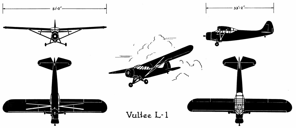 Vultee L-1
Vultee L-1 Front Side Perspective Bottom Top The seaplane shoots off the catapult") The seaplane shoots off the catapult
The seaplane shoots off the catapult
The seaplane shoots off the catapult North American P-51
Front ...") North American P-51
North American P-51
North American P-51 Front Side Perspective Bottom Top Republic P-35
Front Side
...") Republic P-35
Republic P-35
Republic P-35 Front Side Perspective Bottom Top At the beginning of 1909 there were two types of successful aeroplane—the Wright and the Voisin. B...") The Voisin Biplane
The Voisin Biplane
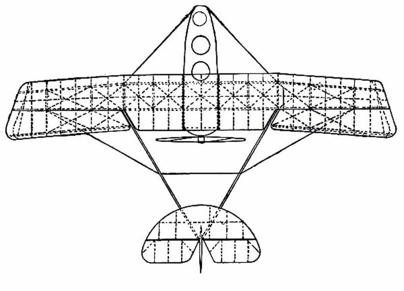
At the beginning of 1909 there were two types of successful aeroplane—the Wright and the Voisin. Bleriot had flown with his monoplane and flown well; but he was still in the process of evolving a practical machine, and several other inventors were in a similar stage. It was the Wright and the Voisin which had proved their worth; and the Wright, as has been said, was the better of the two. Of the Voisin, as flown in 1909, a reproduction is given in the figure. It was a heavier aeroplane than the Wrights’, owing largely to the weight of its alighting gear (250 lbs.) and of its big balancing tail (more than 100 lbs.); hence the necessity for using a 50-h.p. motor, which drove a two-bladed metal propeller at the rate of 1200 revolutions a minute. The Voisin brothers, and other French makers, did not approve of the two-propeller system of the Wrights: they preferred one screw, revolving at high speed. But there was no doubt—at any rate in this stage of aviation—that the Wright method was more efficient than that of the Frenchmen. It was calculated, indeed, that the Wright biplane, when actually in the air, could be driven at an expenditure of only 15 h.p.; whereas the Voisin, even with its 50-h.p. motor running at full speed, had only just enough power to fly. A. Elevating plane B. Pilot’s seat C.C. Main-planes D. Engine and propeller E. Landing chassis F. Balancing tail G. Rudder. Republic P43-A
Front Side ...") Republic P43-A
Republic P43-A
Republic P43-A Front Side Perspective Bottom Top By 1903 the Wright Brothers were ready to build a powered man-carrying flying machine. Their experim...") Wright Brothers first powered airplane
Wright Brothers first powered airplane
By 1903 the Wright Brothers were ready to build a powered man-carrying flying machine. Their experiments had shown them just how much moving air was necessary to create lift in such a machine. To create the needed thrust, an engine having eight horsepower and weighing not over 200 pounds had to be fitted into the machine. Such an engine was not available, so the Wrights built one in their shop at Dayton, Ohio. They were ready to ship their airplane to Kitty Hawk, N. C., in the fall of 1903. Ryan PT-22
Front Side
...") Ryan PT-22
Ryan PT-22
Ryan PT-22 Front Side Perspective Bottom Top Aviators taking photographs") Aviators taking photographs
Aviators taking photographs
Aviators taking photographs North American AT-6A
Front  ...") North American AT-6A
North American AT-6A
North American AT-6A Front Side Perspective Bottom Top Dropping off in parachute from flaming balloon") Dropping off in parachute from flaming balloon
Dropping off in parachute from flaming balloon
Dropping off in parachute from flaming balloon Martin A-30
Front Side
...") Martin A-30
Martin A-30
Martin A-30 Front Side Perspective Bottom Top The story of Dædalus and Icarus also tells us that man believed flying was somehow possible. Dædal...") Daedalus and Icarus
Daedalus and Icarus
The story of Dædalus and Icarus also tells us that man believed flying was somehow possible. Dædalus was a very clever man who lived with his son Icarus on the Island of Crete. The king of this island requested Dædalus to build a labyrinth or maze for him. Dædalus constructed the labyrinth so cleverly that only the king, who had the clue to the winding passages, could find his way out. One day the king became very angry at Dædalus and threw both him and his son Icarus into the labyrinth, intending that they should perish. Dædalus, who had been dreaming of flying, fashioned wings from wax and feathers, with which he and Icarus could fly to freedom. He cautioned Icarus that he must not fly too high or the sun would melt the wax in his wings. Icarus, impatient to escape, scarcely listened. Like birds the two flew into the air, quickly leaving the walls of the labyrinth. Dædalus, flying low, safely crossed the sea and reached Sicily. Icarus, unfortunately, failed to heed his father’s warning. Flying was so much fun that he rose higher and higher. Suddenly feathers began to drop one by one. Too late Icarus realized that the sun had melted the wax in his wings. Down, down he fell into the sea. Bell P-39C & D
Front Side ...") Bell P-39C & D
Bell P-39C & D
Bell P-39C & D Front Side Perspective Bottom Top Republic AT-12
Front Side ...") Republic AT-12
Republic AT-12
Republic AT-12 Front Side Perspective Bottom Top North American O-47A & B
Front &...") North American O-47A& B
North American O-47A& B
North American O-47A & B Front Side Perspective Bottom Top showing the spread of the planes and tail, and the delicate taper of the long, canoe-shaped body.") The Antoinette Monoplane - top view
The Antoinette Monoplane - top view
showing the spread of the planes and tail, and the delicate taper of the long, canoe-shaped body.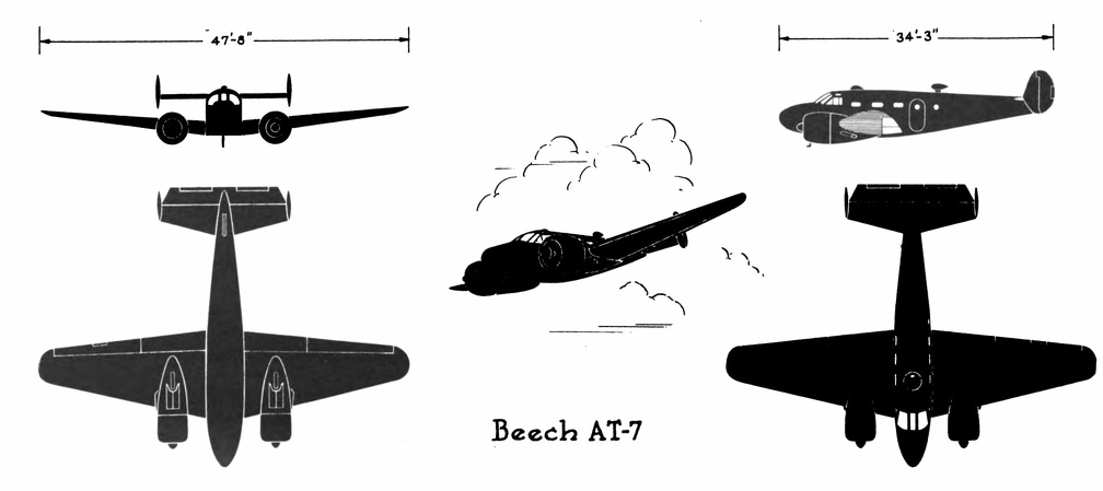 Beech AT-7
Beech AT-7 Front Side Perspective Bottom Top Curtiss C-46
Front Side
...") Curtiss C-46
Curtiss C-46
Curtiss C-46 Front Side Perspective Bottom Top Consolidated OA-10
Front S...") Consolidated OA-10
Consolidated OA-10
Consolidated OA-10 Front Side Perspective Bottom Top Beech AT-10
Front Side
Perspective
Bottom ...") Beech AT-10
Beech AT-10
Beech AT-10 Front Side Perspective Bottom Top Naval battle with planes launched from ships") Naval battle with planes launched from ships
Naval battle with planes launched from ships
Naval battle with planes launched from ships Douglas XB-19
Front Side
...") Douglas XB-19
Douglas XB-19
Douglas XB-19 Front Side Perspective Bottom Top Lockheed P-38D&E
Front Sid...") Lockheed P-38D&E
Lockheed P-38D&E
Lockheed P-38D&E Front Side Perspective Bottom Top They found that a slight curve or camber in the wing section would cause the moving air to travel fa...") Wright Brothers' Wind tunnel
Wright Brothers' Wind tunnel
They found that a slight curve or camber in the wing section would cause the moving air to travel farther over the top of the wing surface than along the under side. This made the air pressure greater under the wing, gave a suction effect above the wing, and caused it to rise, creating lift. They discovered that a wing section of the proper camber would counteract the weight of gravity. Thus, a wing must be so designed that, with a certain amount of air flowing around it, it would lift a certain weight. They also discovered that air flow against any surface attached to the wing would cause a resistance or drag. Hundreds of experiments in their wind tunnel with various types of wing shapes gave the Wrights a series of tables from which to design a wing that would create the lift for a designed weight. Curtis O-52
Front Side
...") Curtis O-52
Curtis O-52
Curtis O-52 Front Side Perspective Bottom Top The Voisin Biplane - top view") The Voisin Biplane - top view
The Voisin Biplane - top view
The Voisin Biplane - top view Lockheed A-29&A
Front Side...") Lockheed A-29&A
Lockheed A-29&A
Lockheed A-29&A Front Side Perspective Bottom Top Douglas C-54A
Front Side
...") Douglas C-54A
Douglas C-54A
Douglas C-54A Front Side Perspective Bottom Top One of the earliest authenticated devices of this kind was the invention of Blanchard, described by ...") Blanchard’s flying-machine
Blanchard’s flying-machine
One of the earliest authenticated devices of this kind was the invention of Blanchard, described by him in the Journal de Paris, August 28, 1781, nearly two years before the invention of the hot-air balloon, of which he became later an enthusiastic votary. As his device is but one of a large number that appeared before the close of the nineteenth century, and the advent of light motors, the reader who wishes fuller acquaintance with man-driven airships may be referred to Mr. Chanute’s book, entitled Progress in Flying-Machines, which describes a large variety of such inventions, and discusses the merit and weakness of each. Curtis P-36C
Front Side
...") Curtis P-36C
Curtis P-36C
Curtis P-36C Front Side Perspective Bottom Top Grumman OA-9
Front Side
...") Grumman OA-9
Grumman OA-9
Grumman OA-9 Front Side Perspective Bottom Top An aeroplane is a necessity in times of peace") An aeroplane is a necessity in times of peace
An aeroplane is a necessity in times of peace
An aeroplane is a necessity in times of peace Douglas C-39
Front Side
...") Douglas C-39
Douglas C-39
Douglas C-39 Front Side Perspective Bottom Top Curtiss P-40E
Front Side
...") Curtiss P-40E
Curtiss P-40E
Curtiss P-40E Front Side Perspective Bottom Top
In July, at Rheims, there was to be the great flying meeting; and Farman had made up his mind to...") The Farman Biplane
The Farman Biplane
In July, at Rheims, there was to be the great flying meeting; and Farman had made up his mind to wait for this. Aided by the experience he had gained with the Voisin machine, he had designed a craft which should be generally more efficient and faster in flight, and more quickly responsive to its controls. The biplane he produced, marking as it did a step forward in construction, is a machine that needs description. The general appearance of the craft is indicated by Fig. 46, while an illustration of this type of machine in flight will be found on Plate VII. A feature of the Voisin that Farman discarded was the vertical panel fitted between the main-planes to give sideway stability. An objection to these planes was that they added to the weight of the machine and checked its speed, tending also to drive it from its course should there be a side wind. But in taking away such fixed balancing-planes, Farman had to substitute another device; and what he did was to work upon the same theory as the Wrights had done, and obtain a similar result in a different way. They, it will be remembered, had warped the rear portions of their main-planes. Farman kept his planes rigid, but fitted to their rear extremities four narrow, hinged planes, or flaps, which could be moved up and down and were called ailerons. Their effect was the same as with the Wright wing-warp. When a gust tilted the machine, the pilot drew down the ailerons upon the side that was inclined downward; whereupon the air-pressure, acting upon the drawn-down surfaces, restored the machine to an even keel. A. Elevating-plane; B.B. Main-planes; C. Pilot’s seat; D. Motor and propeller; E. Petrol tank; F.F. Hinged balancing-planes, or ailerons; G.G. Tail-planes; H.H. Twin vertical rudders; I. Landing wheels and skid Original Wright Biplane") Original Wright Biplane
Original Wright Biplane
Original Wright Biplane Lockheed C60-A
Front Side ...") Lockheed C60-A
Lockheed C60-A
Lockheed C60-A Front Side Perspective Bottom Top Consolidated B-24 D & E
Front &n...") Consolidated B-24 D & E
Consolidated B-24 D & E
Consolidated B-24 D & E Front Side Perspective Bottom Top Coal-gas superseded hot air in the filling of balloons, the latter being unsatisfactory, seeing that...") A modern Balloon
A modern Balloon
Coal-gas superseded hot air in the filling of balloons, the latter being unsatisfactory, seeing that it cooled rapidly and allowed the balloon to descend; the only alternative being to do what some of the first aeronauts did, and burn a fire below the neck of their balloon even when in the air. But the dangers of this were great, seeing that the whole envelope might easily become ignited. With balloons filled with coal-gas long flights were possible, but they had always this disadvantage—the voyagers were at the mercy of the wind, and could not fly in any direction they might choose. If the wind blew from the north then they were driven south, the balloon being a bubble in the air, wafted by every gust. Aeronauts became disgusted with this inability to guide the flight of a balloon, and many quaint controls were tested; such, for example, as the use of a large pair of oars with which the balloonist, sitting in the car of his craft, rowed vigorously in the air. Lockheed C-40A
Front Side ...") Lockheed C-40A
Lockheed C-40A
Lockheed C-40A Front Side Perspective Bottom Top Boeing B-17E
Front Side
...") Boeing B-17E
Boeing B-17E
Boeing B-17E Front Side Perspective Bottom Top A more reasonable plan for practical navigation was devised and tried by the Robert brothers. A melo...") Robert Brothers’ dirigible, 1784
Robert Brothers’ dirigible, 1784
A more reasonable plan for practical navigation was devised and tried by the Robert brothers. A melon-shaped balloon, fifty-two feet long by thirty-two feet in diameter, was made of silk and inflated with pure hydrogen. Beneath was suspended a longish car of light wood covered with sky-blue silk. This elegant ship was to be rowed through heaven by means of six silken oars actuated by sturdy sailors. A silken rudder should guide her at pleasure when the winds were asleep, or softly playing in the placid sky. She was a fairy bark, indeed, a soaring castle lovely to behold. After a preliminary trial, accompanied by their patron, the Duke de Chartres, they were ready for a substantial journey. On September 19, 1784, the vessel was inflated and taken to the Garden of the Tuileries, in front of the palace, where its cords were held by Marshall Richelieu and three other noblemen. At eleven forty-five the two Roberts and their brother-in-law arose and drifted beyond the horizon on a seven hours’ cruise. Before coming to earth, they plied the oars vigorously, and described a curve of one kilometer radius, thus deviating 22° from the feeble wind then prevailing. A \"No. 2 flying boat,\" just built by Mr. Curtiss, and successfully tested on Lake Keuka, Hammondspor...") Diagram of the Curtiss Flying Boat no. 2
Diagram of the Curtiss Flying Boat no. 2
A "No. 2 flying boat," just built by Mr. Curtiss, and successfully tested on Lake Keuka, Hammondsport, in July, 1912, is the "last word" in aviation so far. An illustration in this book, made from photographs taken in mid-July, 1912, shows fully the bullet-shape of the "flying fish." It is a real boat, built with a fish-shaped body containing two comfortable seats for the pilot and passenger or observer, either of whom can operate the machine by a system of dual control, making it also available for teaching the art of flying. All the controls are fastened to the rear of the boat's hull, which makes them very rigid and strong, while the boat itself, made in stream-line form, offers the least possible resistance to the air, even less than that offered by the landing gear upon a standard land machine. Above the boat are mounted the wings and aeroplane surface. In the centre of this standard biplane construction is situated the eighty horse-power motor with its propeller in the rear, thus returning to the original practice, as in the standard Curtiss machines, of having a single propeller attached direct to the motor, thus doing away with all chains and transmission gearing which might give trouble, and differing from the earlier model flying boat built in San Diego, California, last winter (1911-12), which was equipped with "tractor" propellors propellers in front driven by chains. The new flying boat is twenty-six feet long and three feet wide. The planes are five and a half feet deep and thirty feet wide. It runs on the water at a speed of fifty miles an hour, and is driven by an eighty horse-power Curtiss motor. At a greater speed than this it cannot be kept on the water, but rises in the air and flies at from fifty to sixty miles per hour. Curtiss AT-9
Front Side
...") Curtiss AT-9
Curtiss AT-9
Curtiss AT-9 Front Side Perspective Bottom Top German plane crashed into an American warship") A mass of wreckage that strikes the deck of one of our warships
A mass of wreckage that strikes the deck of one of our warships
German plane crashed into an American warship Pilot and passenger") Pilot and passenger
Pilot and passenger
Pilot and passenger Some types of American and foreign aeroplanes") Some types of American and foreign aeroplanes
Some types of American and foreign aeroplanes
Some types of American and foreign aeroplanes The Wright Brothers Aero Engine") The Wright Brothers Aero Engine
The Wright Brothers Aero Engine
The Wright Brothers Aero Engine showing shape and spread of planes and tail, and position of pilot and passenger.") Grahame-White Military Biplane
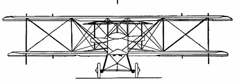
Grahame-White Military Biplane
showing shape and spread of planes and tail, and position of pilot and passenger.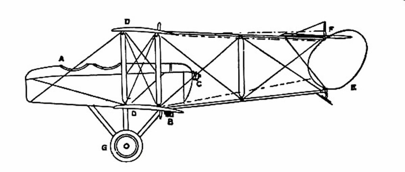
 Some types of American and foreign aeroplanes") Some types of American and foreign aeroplanes
Some types of American and foreign aeroplanes
Some types of American and foreign aeroplanes Following the success of the \"White Wing\" we started in to build another machine, embodying all that...") Scientific American Trophy
Scientific American Trophy
Following the success of the "White Wing" we started in to build another machine, embodying all that we had learned from our experience with the two previous ones. Following our custom of giving each machine a name to distinguish it from the preceding one, we called this third aeroplane the "June Bug." The name was aptly chosen, for it was a success from the very beginning. Indeed, it flew so well that we soon decided it was good enough to win the trophy which had been offered by The Scientific American for the first public flight of one kilometer, or five-eights of a mile, straightaway. This trophy, by the way, was the first to be offered in this country for an aeroplane flight, and the conditions specified that it should become the property of the person winning it three years in succession. The "June Bug" was given a thorough try-out before we made arrangements to fly for the trophy, and we were confident it would fulfill the requirements. showing the chassis and the position between the planes of the two ailerons (A.A.).") The Curtiss Biplane front view
The Curtiss Biplane front view
showing the chassis and the position between the planes of the two ailerons (A.A.). 1. Motor; 2. Radiator; 3. Fuel Tank; 4. Upper Main Plane; 5. Lower Main Plane; 6. Aileron; 7. Vertic...") Diagram of Curtiss Aeroplane, side view
Diagram of Curtiss Aeroplane, side view
1. Motor; 2. Radiator; 3. Fuel Tank; 4. Upper Main Plane; 5. Lower Main Plane; 6. Aileron; 7. Vertical Rudder; 8. Tail Surface; 9. Horizontal Rudder, or Rear Elevator; 10. Front Elevator; 11. Vertical Fin; 12. Steering Wheel; 13. Propeller; 14. Foot Throttle Lever; 15. Hand Throttle Lever; 16. Foot Brake. showing the position of the body and the construction of the landing gear.") Grahame-White Military Biplane - front view
Grahame-White Military Biplane - front view
showing the position of the body and the construction of the landing gear.