


") Space Shuttle - forward and Adt elevations
Space Shuttle - forward and Adt elevations") Space Shuttle - component isometric
Space Shuttle - component isometric A machine that has achieved success, owing to its power of varying speed, is the Sopwith military bi...") Sopwith Military Biplane
Sopwith Military Biplane
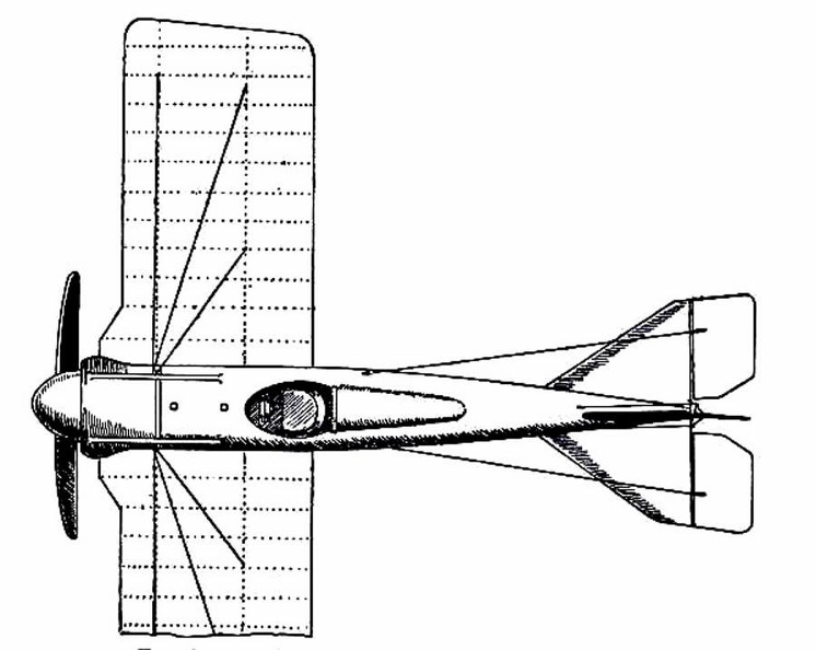
A machine that has achieved success, owing to its power of varying speed, is the Sopwith military biplane. Adopting a practice that has become general, its wings are fitted upon what is practically a monoplane body. Tail-planes and rudder are the same as in a monoplane. The top main-plane, as will be seen, is set slightly in advance of the lower. The system is called “staggering”; and the idea is that, by placing the upper plane ahead of the lower, the total lifting power will be increased. It has been proved a disadvantage of the biplane that, when the main-planes are placed one above another, there is a slight loss of lift owing to the fact that, acting upon the air as they do quite close to each other, a certain amount of interference occurs between them—one tending to disturb the air-stream in which the other moves. By “staggering” the two planes this interference is overcome; but some makers regard it as a small consideration, and build their planes in the ordinary way, allowing as large a gap as possible between them. In the Sopwith military machine, engine and propeller are in front of the main-planes; then come the places for pilot and observer. The pilot sits first, and the body of the machine is so high that only his head appears above it, while just in front of his face, to deflect the wind-rush from the propeller, there is a raised section of the hull which acts as a screen. Behind the pilot, sitting in a second opening in the hull, is the observer. He has a view forward, rendered the better by setting back the lower-plane; while at the point at which it joins the body of the machine, immediately below him, this plane is hollowed out, so that he can look directly upon the earth below. Small windows are also fitted upon either side of the hull. Through those in front the pilot may glance when descending from a flight, so as to judge his distance from the ground, while the others are utilised by the observer, as he turns to look from side to side. This biplane, and many others, is balanced against sideway roll by ailerons, and not by warping the wings. Constant warping, such as is necessary in the everyday use of machines, has been declared to strain a plane and render it weak; therefore the use of ailerons is now favoured. A. Propeller B. Motor, partly hidden by shield C.C. Main-planes D. Pilot’s seat E. Observer’s seat F. Outlook windows in side of hull G. Rudder H. Elevating-plane I. Landing gear. Some types of American and foreign aeroplanes") Some types of American and foreign aeroplanes
Some types of American and foreign aeroplanes
Some types of American and foreign aeroplanes Some types of American and foreign aeroplanes") Some types of American and foreign aeroplanes
Some types of American and foreign aeroplanes
Some types of American and foreign aeroplanes Hence there is a type of fast scouting monoplane, in which a pilot can ascend alone, and fly at 100 ...") Single-seated Air Scout
Single-seated Air Scout
Hence there is a type of fast scouting monoplane, in which a pilot can ascend alone, and fly at 100 miles an hour. With such a craft, sweeping rapidly above an enemy’s position, the pilot-observer can return with his information at surprising speed. In the figure an air-scout of this type is seen. The tapering, covered-in body will be observed; this is to reduce wind resistance as the machine rushes through the air. The Gnome engine is, for the same reason, covered by an aluminium shield, which only allows the lower cylinders to project; they must, of course, be exposed in some way to the air, or they would not cool themselves. The landing-carriage has been reduced to its simplest form; this, again, is to reduce wind resistance; and the pilot, sitting deep in the body, shows only his head as the machine flies. Here, again, apart from the greater comfort in being so shielded, the placing of the pilot within the machine spells a lessening of pressure. A. Propeller B. Motor (partly hidden by shield) C. Pilot’s seat D. Sustaining plane E. Rudder F. Elevating-plane G. Chassis. Shop engine, 1901") Shop engine, 1901
Shop engine, 1901
Shop engine, 1901 Ship saved by life line thrown from a rescue airship
[Not sure what it did to save the boat]") Ship saved by life line thrown from a rescue airship
Ship saved by life line thrown from a rescue airship
Ship saved by life line thrown from a rescue airship [Not sure what it did to save the boat] But as airships were built larger, and greater speeds were obtained, it became necessary to strength...") Semi-rigid Airship
Semi-rigid Airship
But as airships were built larger, and greater speeds were obtained, it became necessary to strengthen the envelopes with some form of keel; and this led to a type which is known as the semi-rigid, and is developed successfully in France. The figure illustrates an airship of this build. Along the lower side of its envelope is placed a light, rigid framework or keel, and from this is suspended the car which contains engines and crew. A. Gas-containing envelope B. Strengthening keel C.C. Stabilising-planes D. Rudder E. Car carrying engines, propeller, and crew. A coastal sea-plane, as now planned, is a craft having, say, two engines, each devolving 120 h.p., w...") Sea-plane to carry a crew of seven
Sea-plane to carry a crew of seven
A coastal sea-plane, as now planned, is a craft having, say, two engines, each devolving 120 h.p., with a wing span of some 80 feet, and an accommodation in its hull for three men—the pilot, a combatant with a machine-gun, and an observer with an installation of wireless. But types are changing constantly, and the tendency is to build larger craft. A machine weighing a couple of tons is shown, and a novelty in regard to it is that it has wheels upon either side of its boat-shaped car, upon which it can move on land, and which fold upward when it rests upon the water. A. Hull upon which the machine floats when in the sea B.B.B. Wheels upon which it may move when on land, and which fold upward when it is on the water C. Pilot’s controlling wheel D.D. Main sustaining planes E. Four-bladed propeller driven by chain-gearing from engine within the hull. (1399 visites) Scouting over the ruined region between the lines (no man’s land)") Scouting over the ruined region between the lines (no man’s land)
Scouting over the ruined region between the lines (no man’s land)
Scouting over the ruined region between the lines (no man’s land) To meet the demand for a purely scouting machine, in which pilot and passenger shall have a clear fi...") Scouting Monoplane, with occupants below the wings.
Scouting Monoplane, with occupants below the wings.
To meet the demand for a purely scouting machine, in which pilot and passenger shall have a clear field for observation, both above and below, a monoplane has been designed which is called the “parasol.” This machine, a Morane-Saulnier, is shown. The two sustaining wings, forming a single surface, are raised above the body so that its occupants have nothing to impede their view earthward; and they can also see above them—an advantage of course in time of war, seeing that an enemy might be hovering overhead A. Engine and propeller B. Plane raised above hull C. Seats for pilot and passenger D. Rudder E. Elevating-plane. Following the success of the \"White Wing\" we started in to build another machine, embodying all that...") Scientific American Trophy
Scientific American Trophy
Following the success of the "White Wing" we started in to build another machine, embodying all that we had learned from our experience with the two previous ones. Following our custom of giving each machine a name to distinguish it from the preceding one, we called this third aeroplane the "June Bug." The name was aptly chosen, for it was a success from the very beginning. Indeed, it flew so well that we soon decided it was good enough to win the trophy which had been offered by The Scientific American for the first public flight of one kilometer, or five-eights of a mile, straightaway. This trophy, by the way, was the first to be offered in this country for an aeroplane flight, and the conditions specified that it should become the property of the person winning it three years in succession. The "June Bug" was given a thorough try-out before we made arrangements to fly for the trophy, and we were confident it would fulfill the requirements. It was not until 1906, at a time when the Wright aeroplane was capable of long flights, that a real ...") Santos-Dumont’s Biplane which flew at Bagetelle
Santos-Dumont’s Biplane which flew at Bagetelle
It was not until 1906, at a time when the Wright aeroplane was capable of long flights, that a real French success was obtained; and then the flights made were brief, and carried out with a craft that was admittedly crude. It was a biplane of curious construction, built by the Voisin brothers for M. Santos-Dumont—a rich Brazilian who had spent money freely upon airships, and had been occupied, for some time before the Voisins made him this machine, with a craft having propellers to lift it vertically from the ground. Abandoning this idea, he devoted himself to the machine the Voisins built, which is seen in the picture. When petrol engines became available, they gave an impetus to the building of airships; for, like th...") Santos-Dumont’s Airship
Santos-Dumont’s Airship
When petrol engines became available, they gave an impetus to the building of airships; for, like the aeroplane, the airship needed a motive agent which gives a high power for a low weight. One of the first to use a petrol motor in an airship with success was M. Santos-Dumont, whose name has been mentioned in connection with aeroplanes. He tested small, light airships, driven by petrol engines and two-bladed propellers—as illustrated in figure; and with one of these, on a calm, still day, he flew over Paris and round the Eiffel Tower. A. Gas envelope B. Wheeled framework which carried motor, propeller, and pilot’s seat C. Elevating-plane D. Horizontal rear-plane E. Rudder. Ryan PT-22
Front Side
...") Ryan PT-22
Ryan PT-22
Ryan PT-22 Front Side Perspective Bottom Top In 1820 Rufus Porter, a Yankee inventor, and later the original founder of the Scientific American, ...") Rufus Porter’s dirigible, 1820
Rufus Porter’s dirigible, 1820
In 1820 Rufus Porter, a Yankee inventor, and later the original founder of the Scientific American, patented an air ship of very promising appearance for that early day. Its hull was a long, finely tapering symmetrical spindle, suspending a car of similar shape by means of cords, which were vertical at its middle but more and more slanting toward its ends. Midway between the hull and car was a large screw propeller actuated by a steam engine in the car. A model of this dirigible exhibited in Boston and New York, some years later, is reported to have carried its own power, at fair speed, and to have obeyed its helm satisfactorily. After four preliminary ascensions the great air ship started from Moisson to her destination at Farn...") Route of British military dirigibles from France to England, 1900
Route of British military dirigibles from France to England, 1900
After four preliminary ascensions the great air ship started from Moisson to her destination at Farnborough, having on board Henri Julliot, Louis Capazza, the pilot, Alexander Bannerman, director of the aëronautic military school at Aldershot, and five other men. It was a triumphant and glorious voyage, one of the most splendid in the history of aërostation. Piloted by aid of chart and compass, and by signal fires and captive balloons arranged along her route, the vessel followed a direct course, without check or hindrance, crossing a wide part of the English Channel and arriving before the hangar at Aldershot, where the British soldiers awaited her, and where she was safely landed, having made the whole voyage of 230 miles in 5.5 hours, at a level varying between five hundred and two thousand feet. As shown by the accompanying map, about one third of the route lay over the Channel, or, more accurately, 78 miles, which was traversed in two hours. Thus the whole journey was accomplished at an average speed of nearly forty-two miles an hour, or in less time than it could be effected in any other way than through the air. A more reasonable plan for practical navigation was devised and tried by the Robert brothers. A melo...") Robert Brothers’ dirigible, 1784
Robert Brothers’ dirigible, 1784
A more reasonable plan for practical navigation was devised and tried by the Robert brothers. A melon-shaped balloon, fifty-two feet long by thirty-two feet in diameter, was made of silk and inflated with pure hydrogen. Beneath was suspended a longish car of light wood covered with sky-blue silk. This elegant ship was to be rowed through heaven by means of six silken oars actuated by sturdy sailors. A silken rudder should guide her at pleasure when the winds were asleep, or softly playing in the placid sky. She was a fairy bark, indeed, a soaring castle lovely to behold. After a preliminary trial, accompanied by their patron, the Duke de Chartres, they were ready for a substantial journey. On September 19, 1784, the vessel was inflated and taken to the Garden of the Tuileries, in front of the palace, where its cords were held by Marshall Richelieu and three other noblemen. At eleven forty-five the two Roberts and their brother-in-law arose and drifted beyond the horizon on a seven hours’ cruise. Before coming to earth, they plied the oars vigorously, and described a curve of one kilometer radius, thus deviating 22° from the feeble wind then prevailing. Republic P43-A
Front Side ...") Republic P43-A
Republic P43-A
Republic P43-A Front Side Perspective Bottom Top Republic P-47B
Front Side ...") Republic P-47B
Republic P-47B
Republic P-47B Front Side Perspective Bottom Top Republic P-35
Front Side
...") Republic P-35
Republic P-35
Republic P-35 Front Side Perspective Bottom Top Republic AT-12
Front Side ...") Republic AT-12
Republic AT-12
Republic AT-12 Front Side Perspective Bottom Top Captain Charles Renard proved to be a worthy inheritor of the dreams, experience and inventions of t...") Renard’s dirigible, La France, 1884
Renard’s dirigible, La France, 1884
Captain Charles Renard proved to be a worthy inheritor of the dreams, experience and inventions of the first century of aëronautical votaries. He did not, indeed, have the picturesque madness displayed by some of his predecessors; he did not project schemes of marvelous originality or boldness; but he manifested uncommonly good judgment and excellent scientific method in combining the researches and contrivances of others with those of himself and his collaborator, Captain Krebs. As a consequence they produced the first man-carrying dirigible that ever returned against the wind to its starting point, and the first aërial vessel whose shape and dynamic adjustment even approximated the requirements of steady and swift navigation in a surrounding medium presenting various conditions of turbulence or calm. (909 visites)") Racing Deperdussin Monoplane (top view)
Racing Deperdussin Monoplane (top view) (803 visites) In the development of speed, some remarkable craft are built. Each year there is an international ai...") Racing Deperdussin Monoplane (side view)
Racing Deperdussin Monoplane (side view)
In the development of speed, some remarkable craft are built. Each year there is an international air race for the possession of the Gordon-Bennett trophy, and to win this designers build special craft. In tiny monoplanes, engines of high power are installed; and the sustaining wings are so reduced, to give a maximum speed, that the machines appear more like projectiles than flying craft. A purely racing-type monoplane is seen in figure.. It represents a Deperdussin, which, with an engine of 160 horse-power, reached a speed of 130 miles an hour. How small this machine was, in relation to its engine-power, will be realised from the fact that the sustaining surface of its wings amounted to only 104 square feet—far less lifting area, in fact, than Lilienthal used in his gliders. Wires and struts are reduced to a minimum; the body is tapered and smoothed. Such a machine, although it carries speed to an extreme, and is in reality a “freak,” teaches useful lessons. But though it provides data for the construction of high-speed scouts, a monoplane of this type would be useless for cross-country flying; and for the reason that it cannot be manœuvred, prior to an ascent, upon anything save the smoothest of ground. Its wings being so small, to ensure a maximum of speed, the machine will not rise until it has run forward a long distance across the ground; and during this run it attains a speed of nearly 90 miles an hour. At such a pace, unless the ground below its wheels was level, it would leap, swerve, and probably overturn. When alighting from a flight, also, again owing to the smallness of its wings, the craft has to plane down so fast that its pilot could not land safely unless he had below him a surface that was absolutely smooth. A. Propeller B. Shield to lessen wind resistance C. Sloping shield which encloses engine (also to minimise wind-pressure). Air passes between the shields B and C to cool the motor. D. Pilot’s seat E. Padded projection against which, when at high speed, the pilot rests his head F. Sustaining-plane Very slightly cambered G. Rudder H. Elevating-plane I. Landing wheels.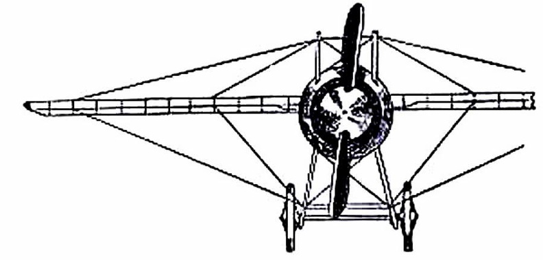
 (811 visites) showing the “stream-line” effect which is gained by tapering the body, also the simplification o...") Racing Deperdussin Monoplane (front view)
Racing Deperdussin Monoplane (front view)
showing the “stream-line” effect which is gained by tapering the body, also the simplification of the landing chassis, and the use of a minimum of wires. photo id=7984] Plane going down in flames") Plane going down in flames
Plane going down in flames
Plane going down in flames Pilot and passenger") Pilot and passenger
Pilot and passenger
Pilot and passenger Phillips built the strange-looking machine. It resembled, more than anything else, a huge Venetian b...") Phillips’s Experimental Craft
Phillips’s Experimental Craft
Phillips built the strange-looking machine. It resembled, more than anything else, a huge Venetian blind; and he adopted this form so as to introduce as many narrow planes as possible. There were, as a matter of fact, fifty in the machine, each 22 feet long and only 1½ inch wide. The craft, as can be seen, was mounted on a light carriage which, having wheels fitted to it, ran round and round upon a railed track. A steam engine was used as motive power, driving a two-bladed propeller at the rate of 400 revolutions a minute. The machine was so arranged on its metals that, although the rear wheels could raise themselves and show whether the planes exercised a lift, the front one was fixed to its track—thus preventing the apparatus from leaping into the air, overturning, and perhaps wrecking itself. Tests with the machine were successful. The lifting influence of the planes, when the engine drove them forward, was sufficient to raise the rear wheels from the track; and they did so even when a weight of 72 lbs., in addition to that of the apparatus, had been placed upon the carriage. In his main object, then, Phillips succeeded; and that was to show the lifting power of his planes. But his apparatus had not the makings of a practical aeroplane. He gained for himself, nevertheless, a name that has lived and will live. In 1871 M. A. Penaud produced the interesting toy aëroplane shown in the figure. The model is prope...") Penaud’s aëroplane toy, 1871
Penaud’s aëroplane toy, 1871
In 1871 M. A. Penaud produced the interesting toy aëroplane shown in the figure. The model is propelled horizontally forward by a single screw, actuated by twisted rubber, and is fastened, as shown, to the middle of a long stick or backbone. The center of mass of the machine is well to the front, tending to plunge the model earthward like a heavy-headed arrow; but this down-diving is promptly checked by the tiny rudder which is so inclined as to counteract the diving proclivity. That is to say the rudder dips so as to receive the aërial impact on its upper surface; which impact increases with the speed of flight and causes the bow to rise, until the weight before the wings just balances the impact on the rudder at the rear. The equilibrium is thus automatic, on the principle expounded by Sir George Cayley sixty years earlier. Original Wright Biplane") Original Wright Biplane
Original Wright Biplane
Original Wright Biplane Octave Chanute, born in France and reared in America, was one of the first men to make a scientific ...") Octave Chanute experimenting with his gliders on the Michigan sand dunes
Octave Chanute experimenting with his gliders on the Michigan sand dunes
Octave Chanute, born in France and reared in America, was one of the first men to make a scientific approach to the problem of flying machines. A thorough scientist, he had followed the progress of all flight experiments the world over. He built gliders with one, two, and even five pairs of wings and tested all of them on the sand dunes of Lake Michigan. His most successful glides were made with a biplane glider. In 1894, he published a book called Progress of Flying Machines, which covered all the efforts of men like himself who had experimented with man-carrying gliders and flying machines. Northrop A-17
Front Side
...") Northrop A-17
Northrop A-17
Northrop A-17 Front Side Perspective Bottom Top North American P-51
Front ...") North American P-51
North American P-51
North American P-51 Front Side Perspective Bottom Top North American O-47A & B
Front &...") North American O-47A& B
North American O-47A& B
North American O-47A & B Front Side Perspective Bottom Top North American B-25 C & D
Front ...") North American B-25 C & D
North American B-25 C & D
North American B-25 C & D Front Side Perspective Bottom Top North American AT-6A
Front  ...") North American AT-6A
North American AT-6A
North American AT-6A Front Side Perspective Bottom Top Naval battle with planes launched from ships") Naval battle with planes launched from ships
Naval battle with planes launched from ships
Naval battle with planes launched from ships The fitting of several motors has been shown to be practical; and it has the obvious advantage that,...") Multiple-engined craft
Multiple-engined craft
The fitting of several motors has been shown to be practical; and it has the obvious advantage that, should one fail while in the air, the other or others will maintain a craft in flight. In such a machine as would fly the Atlantic, for example, it is proposed to fit four motors developing 800 h.p., and to carry a couple of mechanics who would constantly be tending them. Thus, should one engine develop trouble, its repair could be effected without descent, and with no worse result than a temporary fall in speed. In the figure is shown a method by which three Gnome motors may be fitted to a biplane. A. First engine (a 50-h.p. Gnome) B. Second engine (which is on the same shaft, but will run independently) C. Third Gnome engine, also an independent unit D. Four-bladed propeller (mounted higher than the crank-shaft bearing the engines, and driven by a chain gearing). But Mouillard did more than theorize; he built soaring machines and soared a little. His third and b...") Mouillard’s aëroplane
Mouillard’s aëroplane
But Mouillard did more than theorize; he built soaring machines and soared a little. His third and best glider, illustrated, was a tailless monoplane made of curved agave sticks screwed to boards, and covered with muslin. The aviator, standing in the open space C, harnessed the plane on with straps looped round his legs and shoulders, and fastened to the points D D. His forearms, passing under straps, rested on the board, enabling him to tilt the whole by shifting his weight The dirigible to be purchased with the money secured by the popular subscription organized by the Mo...") Morning Post dirigible, 1910
Morning Post dirigible, 1910
The dirigible to be purchased with the money secured by the popular subscription organized by the Morning Post was ordered from the Lebaudy factory at Moisson in July, 1909, to be delivered directly through the air to Farnborough before November 6, 1910. This stipulation was severe enough, but furthermore the vessel was to be a considerable departure from any thus far built at that famous factory, and was to be the largest air ship yet constructed in France. As usual the general design of the huge balloon was entrusted to the distinguished aëronautical engineer, Henri Julliot, and this was a certain guarantee of its successful operation. Stephen Montgolfier now wishing to send up human passengers, made a balloon of 100,000 cubic feet ca...") Montgolfier’s passenger balloon
Montgolfier’s passenger balloon
Stephen Montgolfier now wishing to send up human passengers, made a balloon of 100,000 cubic feet capacity. It was shaped like a full lemon pointing upward, with a cylindrical neck below, 16 feet in diameter. Around this neck was a wicker balcony three feet wide, to carry the aëronauts, bundles of straw for fuel, pails of water and sponges to extinguish incipient conflagrations, here and there in the balloon, during a journey. Through stokeholes in the side of the neck sheaves of straw could be forked to the grate suspended centrally below by radial chains. During inflation the base of the balloon rested on a platform, and its top was supported by a rope stretched between two poles. The vessel when completed, in a garden of the Faubourg St. Antoine, was 85 feet high by 48 feet across, and weighed 1,600 pounds. About its zone, painted in oil, were elegant decorations; portraits, cyphers of the king’s name, fleur-de-lis, with fancy borders below and above; while higher still, on the arching dome of the bag, were all the signs of the celestial zodiac. The public inauguration of aëronautics occurred on June 5, 1783, at Annonay, the home of the Montgo...") Montgolfier’s experimental balloon
Montgolfier’s experimental balloon
The public inauguration of aëronautics occurred on June 5, 1783, at Annonay, the home of the Montgolfier family, 36 miles from Lyons. The states of Vivarais being assembled at that place, were invited to witness the ascension. The Deputies and many spectators found in the public square an enormous bag which, with its frame, weighed 300 pounds, and would inflate to a ball 35 feet in diameter. When told that this huge mass would rise to the clouds they were astonished and incredulous. The Montgolfiers, however, lit a fire beneath and let the bag speak for itself. It gradually distended, assuming a beautiful form, and struggling to free itself from the men who were holding it. At a given signal it was released; it ascended rapidly, and in ten minutes attained a height of 6,000 feet. It drifted a mile and a half and sank gently to the ground. (Early Type)
A. Elevating-plane
B. Seats for pilot and passenger
C. Main-planes
D. Motor with...") Maurice Farman Biplane
Maurice Farman Biplane
(Early Type) A. Elevating-plane B. Seats for pilot and passenger C. Main-planes D. Motor with two-bladed propeller E. Vertical panel F. Aileron G. Tail-planes H. Rudders I. Landing chassis. Martin B-26 B& C
Front Sid...") Martin B-26 B& C
Martin B-26 B& C
Martin B-26 B& C Front Side Perspective Bottom Top Martin B-10B
Front Side
...") Martin B-10B
Martin B-10B
Martin B-10B Front Side Perspective Bottom Top Martin A-30
Front Side
...") Martin A-30
Martin A-30
Martin A-30 Front Side Perspective Bottom Top How lightly a petrol engine can be made was demonstrated by the firm constructing the Antoinette mo...") Man lifting a 100 horse-power aeroplane motor
Man lifting a 100 horse-power aeroplane motor
How lightly a petrol engine can be made was demonstrated by the firm constructing the Antoinette motor, with which many of the pioneers fitted their craft. A 16-cylinder engine was made so that a man could raise it upon his shoulders—as shown in Figure —and carry it without much difficulty; and yet this same motor, which one man could lift from the ground, developed 100 horse-power. “Looping the loop,” which has made so great a sensation, has taught airmen one definite lesson; ...") Looping the loop
Looping the loop
“Looping the loop,” which has made so great a sensation, has taught airmen one definite lesson; and it is this: no matter how their machines may be beaten and tossed by the wind, they need not fear a fall—provided they are high enough above ground. The movements of a machine, as it makes a series of “loops,” are shown in the figure. The pilot reaches a high speed before he rears up his machine to begin the “loop,” and this downward velocity is attained by diving; then, when he estimates his pace sufficient, he pulls his elevating-lever back and the machine leaps upward, rearing itself vertically towards the sky, turning over on its back, then diving again and coming right-side-up—thus achieving a complete somersault. A skilled trick-flyer, also, will allow his machine to drop sideways or tail first, deliberately working the controls so that it shall do so. Then, just as it seems to spectators that he is falling to destruction, he will dive or twist, regain the mastery of his machine, and descend in a normal glide. Lockheed P-38D&E
Front Sid...") Lockheed P-38D&E
Lockheed P-38D&E
Lockheed P-38D&E Front Side Perspective Bottom Top Lockheed C60-A
Front Side ...") Lockheed C60-A
Lockheed C60-A
Lockheed C60-A Front Side Perspective Bottom Top Lockheed C-40A
Front Side ...") Lockheed C-40A
Lockheed C-40A
Lockheed C-40A Front Side Perspective Bottom Top Lockheed A-29&A
Front Side...") Lockheed A-29&A
Lockheed A-29&A
Lockheed A-29&A Front Side Perspective Bottom Top Lilienthal was fascinated by the mechanism of the bird’s wing. He and his brother built one machin...") Lilienthal's Experiments
Lilienthal's Experiments
Lilienthal was fascinated by the mechanism of the bird’s wing. He and his brother built one machine after another to determine the exact amount of lifting effort that a man could obtain by imitating the wing-beat of a bird. One such apparatus is illustrated. This had a double set of wings; a wide pair in the centre and narrower ones in front and at the rear. These wings beat alternately, by movements of the operator’s legs; and the machine was suspended by a rope and pulleys from a beam, being counterbalanced by a weight. The tests showed this: that, after some practice in working the wings, a man could raise with them just half the weight of himself and of the machine; but the muscular effort proved so great that he could only maintain this rate of wing-beating for a few seconds. Here, incidentally, a fact may be mentioned: the energy a man can produce, at all events for a prolonged effort, has been estimated at about a quarter of a horse-power; and this—in tests so far made—has been insufficient for the purpose of wing-flapping flight. Now, patient and assiduous, he (Lilienthal) began to teach himself the art of aerial balance. Raisin...") Lilienthal gliding
Lilienthal gliding
Now, patient and assiduous, he (Lilienthal) began to teach himself the art of aerial balance. Raising his wings to his shoulders he would face the wind—which in his first tests he did not care to be blowing at more than ten or fifteen miles an hour. Then, running against the wind to increase the pressure beneath his wings, he would raise his legs and begin to glide, moving forward and at the same time downward. How he appeared when in flight is indicated by the picture. Leonardo da Vinci, the great Italian artist and scientist, who lived in the fifteenth century, spent...") Leonardo da Vinci's Glider and Parachute Idea
Leonardo da Vinci's Glider and Parachute Idea
Leonardo da Vinci, the great Italian artist and scientist, who lived in the fifteenth century, spent years experimenting with the idea of flying. He made a number of sketches of wings to be fitted to the arms and legs of man. His plan for a parachute was soundly worked out and his idea that the wings of a flying machine should be patterned after the wings of the bat found expression in the doped fabric covering of our early airplanes. Previous to Lenormand’s experiments, Blanchard, the aëronaut, had dropped small parachutes from h...") Lenormand’s parachute, 1784
Lenormand’s parachute, 1784
Previous to Lenormand’s experiments, Blanchard, the aëronaut, had dropped small parachutes from his balloon, sometimes carrying animals, but never a human being. For unaccountable reasons the world had to wait fourteen years longer to see a man make the new familiar parachute descent from a balloon. On October 22, 1797, in presence of a large crowd Jacques Garnerin ascended in a closed parachute to a height of 3,000 feet, then cut loose. The people were astonished and appalled; but they soon saw the umbrella-shaped canvas spread open and oscillate in the sky with its human freight. As it was but eight yards in diameter, it descended rapidly and struck the ground with violence, throwing Garnerin from his seat. He escaped with a bruised foot, mounted a horse, and returned to the starting point, where he received a lively ovation. Besides the great auto balloons designed by Julliot and Surcouf, of which the République and Colone...") Le Petit Journal, Zodiac type
Le Petit Journal, Zodiac type
Besides the great auto balloons designed by Julliot and Surcouf, of which the République and Colonel Renard are examples, a number of convenient cruisers were brought forth in 1909 by the Zodiac Company. One of the leading spirits in this enterprise was the famous Count de la Vaulx, well known for his auto balloon designs and his long voyages in sphericles. The chief merit of these modest air ships, which ranged in volume from 25,000 cubic feet upwards, was cheapness and facility of demounting and shipment. They were intended to popularize the art among the masses, by giving everyone a chance to make a voyage at no great expense. Besides their applicability to sport, touring, and public uses, some were designed for considerable speed and endurance; which qualities, together with their demountability and partial independence of hangars, were expected to give them military value. n experienced sailor, Captain Le Bris, having observed the albatross soaring without wing-beat, dete...") Le Bris’ aëroplane, 1855
Le Bris’ aëroplane, 1855
n experienced sailor, Captain Le Bris, having observed the albatross soaring without wing-beat, determined to imitate the fascinating flight of that limber-winged spirit of the sea. To such end he built the bird shown, a ninety-pound albatross, with arched wings fifty feet across and articulated to the boat-like body. In this the brave aviator would stand upright, turn the wings and tail to maintain his balance, and steer grandly through the sky. Placing this long-winged creature across a cart driven by a peasant, he stood erect and headed against a breeze; the wings set low to prevent lifting till an opportune moment, and the bird held down to the car by a rope which the captain could quickly release. When the horse was a-trot, and the wind blowing freshly, Le Bris raised the front edges of the wings.