


 Mr. Higginson’s Transfusion Instrument
Although some of the early experiments on blood transfus...") Mr. Higginson’s Transfusion Instrument
Mr. Higginson’s Transfusion Instrument
Mr. Higginson’s Transfusion Instrument Although some of the early experiments on blood transfusion had been done in England, and although its revival [14]in the nineteenth century was initiated in England, yet it is to be noticed that most of the references to it up to 1874 are to be found in the works of Continental writers. Nevertheless, an important modification was introduced into the technique of the operation in 1857 by Higginson, who applied the principle of a rubber syringe with ball-valves for transferring the blood from the receptacle into which it was drawn, to the vein of the recipient. This apparatus is illustrated here, as it is of some interest in the history of medicine. A is a metallic cup, of 6-oz. capacity, to receive the supply of blood. B an outer casing, which will hold 5 oz. of hot water, introduced through an aperture at C. D is a passage leading into an elastic barrel, composed of vulcanized india-rubber, E, of which the capacity is 1 oz. F′ the exit for the blood into the injection-pipe G. At D and F there are ball-valves, capable of closing the upper openings when thrown up against them, but leaving the lower openings always free. The blood, or other fluid, poured into the cup A, has free power to run unobstructed through D, E, F; a small plug H is therefore provided to close the lower aperture F when necessary. The tube G is of vulcanized india-rubber, and terminates in a metal tube O for insertion into the vein. Whole Blood Transfusion with Kimpton’s Tube.
The principle of this method depends upon the use ...") Kimpton-Brown Tube
Kimpton-Brown Tube
Whole Blood Transfusion with Kimpton’s Tube. The principle of this method depends upon the use of paraffin wax as a coating for the vessel into which the blood is drawn, so that clotting is prevented or greatly delayed. The form of the vessel has been modified by different workers, but the essentials are the same in each. One form of the apparatus, known as the Kimpton-Brown tube, is illustrated in the accompanying diagram. It consists of a graduated glass cylinder, of about 700 cc. capacity, the lower end of which is drawn out into a cannula point at an acute angle with the body of the cylinder; the point is of a size convenient for introducing into a vein and its bore large enough to allow of a free flow of blood through it. Near the upper end is a side tube to which a rubber tube can be attached, and an opening at the top is closed by a rubber bung. An ordinary rubber double-bulb bellows is the only other apparatus that is needed. When the donor’s arm has been congested by gripping it above the elbow, or better by the applicati...") Drawing Blood for Transfusion
Drawing Blood for Transfusion
When the donor’s arm has been congested by gripping it above the elbow, or better by the application of a tourniquet drawn to the requisite degree of tightness, a suitable vein, usually the median basilic, is chosen. The area of puncture is washed with ether and a very small quantity, 2 to 3 minims, of 2 per cent. novocain is introduced over the vein with a hypodermic syringe. If a larger quantity is used, the vein may become obscured, but this small amount may be dispersed by a few moments’ pressure with the finger, and is usually enough to anæsthetize the very small area of skin that is to be operated upon. A tiny cut in the skin is then made with the point of a scalpel, and the needle is pushed through into the vein. A more general interest in the subject was revived in England by the work of James Blundell, lecture...") Blundell’s Impellor
Blundell’s Impellor
A more general interest in the subject was revived in England by the work of James Blundell, lecturer on physiology and midwifery at St. Thomas’s and Guy’s Hospitals. He published in 1818 his earliest paper on experimental transfusion with a special form of syringe invented by himself. His first apparatus consisted of a funnel-shaped receptacle for the blood, connected by a two-way tap with a syringe from which the blood was injected through a tube and cannula into the recipient. His experiments were[11] performed upon dogs, and he began by drawing blood from the femoral artery and re-injecting it into the same animal through the femoral vein. He then conducted a long series of investigations into the properties of blood, the effects of its withdrawal, and the resuscitation of an exsanguinated animal. Soon he had opportunities of transfusing patients with human blood, and the results are recorded in his paper of 1824. His apparatus had by then been elaborated, and an engraving of his Impellor, as he termed it, is reproduced here. It consisted as before of a funnel-shaped receptacle for the blood, but the syringe was now incorporated in one side of the funnel, and contained a complicated system of spring valves, which caused the blood to travel along the delivery tube when the piston was pushed down. The Impellor was fixed to the back of a chair in order to give it stability. By 1903 the Wright Brothers were ready to build a powered man-carrying flying machine. Their experim...") Wright Brothers first powered airplane
Wright Brothers first powered airplane
By 1903 the Wright Brothers were ready to build a powered man-carrying flying machine. Their experiments had shown them just how much moving air was necessary to create lift in such a machine. To create the needed thrust, an engine having eight horsepower and weighing not over 200 pounds had to be fitted into the machine. Such an engine was not available, so the Wrights built one in their shop at Dayton, Ohio. They were ready to ship their airplane to Kitty Hawk, N. C., in the fall of 1903. After a year of exhaustive study and experiments with models in their wind tunnel, the Wright Brothe...") The Wright Brothers experimental glider
The Wright Brothers experimental glider
After a year of exhaustive study and experiments with models in their wind tunnel, the Wright Brothers were ready to experiment with a man-carrying glider. With the thoroughness that was typical of every move of the Wrights, the brothers asked the government to let them have information on meteorological conditions all over the country. By studying the weather charts they were able to find a locality where there was a continual flow of wind. This would be nature’s wind tunnel where they could test their glider day after day. Through their study of the charts they found that the wind conditions at Kitty Hawk, on the North Carolina coast, seemed to offer the best possibilities for their glider test. Orville and Wilbur Wright began their experiments with a small man-carrying glider at Kitty Hawk in 1900. From that time until 1903 they made hundreds of successful glider flights and kept accurate records of each flight. They recorded wind velocity, angle of flight, duration of flight, time of day, temperature, humidity, and sky conditions overhead with the typical Wright attention to detail. Each year the Wrights constructed new gliders which embodied principles they had discovered for themselves during their flights at Kitty Hawk. Each glider was larger and had longer and narrower wings than the one before. During the fall of 1902 the brothers recorded nearly a thousand flights in a glider with a wingspan of thirty-two feet. It had a front elevator and a vertical tail which helped to maintain lateral stability. after testing more than 200 wing designs and plane surfaces in their wind tunnel, the Wright Brother...") The Four forces of flight
The Four forces of flight
after testing more than 200 wing designs and plane surfaces in their wind tunnel, the Wright Brothers found out how to figure correctly the amount of curve, or camber, that was essential to weight-carrying wings. They discovered, too, that before man could be flown through the air, he must have his wings attached firmly to a body or platform which was firm and controllable. The Wrights in their earliest experiments had realized that to be practical their machine must be built not only to fly in a straight line, but also in order that it could be steered to the right or to the left. One day, Orville was twisting a cardboard box in his hand when Wilbur noticed it. Immediately he saw the solution to the problem of steering their airplane. The result was a design which changed the lift of either end of the wing by warping its surface. If one end of the wing was warped to give it more lift, the machine would lift on that side and fall off into a turn. Thus the problem of steering was solved by the Wrights They found that a slight curve or camber in the wing section would cause the moving air to travel fa...") Wright Brothers' Wind tunnel
Wright Brothers' Wind tunnel
They found that a slight curve or camber in the wing section would cause the moving air to travel farther over the top of the wing surface than along the under side. This made the air pressure greater under the wing, gave a suction effect above the wing, and caused it to rise, creating lift. They discovered that a wing section of the proper camber would counteract the weight of gravity. Thus, a wing must be so designed that, with a certain amount of air flowing around it, it would lift a certain weight. They also discovered that air flow against any surface attached to the wing would cause a resistance or drag. Hundreds of experiments in their wind tunnel with various types of wing shapes gave the Wrights a series of tables from which to design a wing that would create the lift for a designed weight. The Wright Brothers were not only inspired mechanics (as many people still believe today) but seriou...") Wright Brotherrs wind tunnel
Wright Brotherrs wind tunnel
The Wright Brothers were not only inspired mechanics (as many people still believe today) but serious scientists, working along the soundest lines. In their keen desire to know what air pressure on wings really was, they cleared a corner of their bicycle shop and built a small wind tunnel with spare lumber and an old electric fan. They built small wing sections of various shapes and experimented with them in their wind tunnel. The electric fan was used to create the moving air around the wing section. By attaching the wing sections to a supporting frame and connecting the frame with a pointer and dial, they were able to keep a record of the effect of moving air on each experimental wing section. Through their wind tunnel research the Wright Brothers discovered the four forces that control all heavier-than-air flight: lift, thrust, weight, and drag. Out in Dayton, Ohio, there were two small brothers, who dreamed, as countless other children before ...") Wright Brothers' Bicycle shop
Wright Brothers' Bicycle shop
Out in Dayton, Ohio, there were two small brothers, who dreamed, as countless other children before them had dreamed, of flying like birds through the air. Their dreams were heightened by a small toy given to them by their father, the pastor of a local church. This toy was to lead to an idea which had a profound effect on the world. You would probably call it a flying propeller. It consisted of a wooden propeller which slipped over a notched stick. By placing a finger against the propeller and rapidly pushing it up the notched stick, the propeller was made to whirl up off the end of the stick and fly into the air. The brothers, young as they were, never quite forgot this little toy as they continued to dream of flying like birds through the air. Though the brothers continued to dream of flying, they were not the kind of lads who spent all their time in dreaming. They made kites which flew a little better and a little higher than those made by the other boys in the neighborhood. They built a press to print their own little newspaper, and they dabbled in woodcuts. To carve out porch posts for their father’s home they built an eight-foot wood-turning lathe. Indeed, they were the sort of boys who caused the neighbors to say, “What will they think of next?” The brothers knew that if they ever wanted to see their dreams come true they must earn their own capital. In the early nineties America was in the midst of the bicycle craze. Everyone who could possibly afford to do so owned a bicycle of some sort and belonged to a cycle club. Being mechanically minded, the brothers did the logical thing. They set themselves up in a small bicycle shop in Dayton, next door to their home. The bicycle shop in Dayton prospered, for the brothers were careful and expert mechanics, and cyclists in need of repairs made their way to the Wright Brothers’ shop. Langley built his plane without much difficulty, but could not find anyone to make an engine large e...") The Aerodrome
The Aerodrome
Langley built his plane without much difficulty, but could not find anyone to make an engine large enough for it. Finally, Charles Manley, an expert engineer, asked for permission to build the engine. Manley’s engine was a five-cylinder, radial gasoline engine that developed 51 horsepower and was far ahead of its time. It was years before American radial engines were used successfully in airplanes. Professor Langley called his machine the Aerodrome, and by October, 1903, the plane was ready for its test flight, with Manley to guide it. The Aerodrome was to be launched from a catapulting platform built on the roof of a houseboat. The houseboat was anchored on the Potomac River near Washington. As it left the platform the machine crashed into the river, and the trial was a dismal failure. The newspapers and the public ridiculed Langley, but he and Manley, who was unhurt in the crash, repaired the machine for another trial. This test took place on December 8, 1903, and again the Aerodrome crashed into the river. Manley once more escaped injury, but Langley and the government were abused by the public for wasting money. Langley was out of money himself, the government could not furnish funds for further trials, so the experiments were ended. The professor, discouraged and brokenhearted, gave up. Octave Chanute, born in France and reared in America, was one of the first men to make a scientific ...") Octave Chanute experimenting with his gliders on the Michigan sand dunes
Octave Chanute experimenting with his gliders on the Michigan sand dunes
Octave Chanute, born in France and reared in America, was one of the first men to make a scientific approach to the problem of flying machines. A thorough scientist, he had followed the progress of all flight experiments the world over. He built gliders with one, two, and even five pairs of wings and tested all of them on the sand dunes of Lake Michigan. His most successful glides were made with a biplane glider. In 1894, he published a book called Progress of Flying Machines, which covered all the efforts of men like himself who had experimented with man-carrying gliders and flying machines. Leonardo da Vinci, the great Italian artist and scientist, who lived in the fifteenth century, spent...") Leonardo da Vinci's Glider and Parachute Idea
Leonardo da Vinci's Glider and Parachute Idea
Leonardo da Vinci, the great Italian artist and scientist, who lived in the fifteenth century, spent years experimenting with the idea of flying. He made a number of sketches of wings to be fitted to the arms and legs of man. His plan for a parachute was soundly worked out and his idea that the wings of a flying machine should be patterned after the wings of the bat found expression in the doped fabric covering of our early airplanes. In 1678, Besnier, a French locksmith, constructed a curious flying machine consisting of two wooden ...") Besnier and his wings
Besnier and his wings
In 1678, Besnier, a French locksmith, constructed a curious flying machine consisting of two wooden bars which rested on his shoulders. At the ends of the bars he attached muslin wings, arranged to open on the down stroke and close on the up stroke. The wings were operated by moving the arms and legs. Although Besnier failed to realize that no man had sufficient muscular strength to fly as the bird flies, he did sense part of the truth—that gliding with the air currents was possible. During his experiments he is said to have jumped from a window sill, glided over the roof of a near-by cottage, and landed on a barge in the river. Historians have unearthed stories in cuneiform writing of man’s attempts to fly. Some of these ins...") The flight of Etana
The flight of Etana
Historians have unearthed stories in cuneiform writing of man’s attempts to fly. Some of these inscriptions date back more than five thousand years, to 3500 B.C. Perhaps the most famous of these stories is the ancient Babylonian tale of the shepherd boy, Etana, who rode on the back of an eagle. The story of Dædalus and Icarus also tells us that man believed flying was somehow possible. Dædal...") Daedalus and Icarus
Daedalus and Icarus
The story of Dædalus and Icarus also tells us that man believed flying was somehow possible. Dædalus was a very clever man who lived with his son Icarus on the Island of Crete. The king of this island requested Dædalus to build a labyrinth or maze for him. Dædalus constructed the labyrinth so cleverly that only the king, who had the clue to the winding passages, could find his way out. One day the king became very angry at Dædalus and threw both him and his son Icarus into the labyrinth, intending that they should perish. Dædalus, who had been dreaming of flying, fashioned wings from wax and feathers, with which he and Icarus could fly to freedom. He cautioned Icarus that he must not fly too high or the sun would melt the wax in his wings. Icarus, impatient to escape, scarcely listened. Like birds the two flew into the air, quickly leaving the walls of the labyrinth. Dædalus, flying low, safely crossed the sea and reached Sicily. Icarus, unfortunately, failed to heed his father’s warning. Flying was so much fun that he rose higher and higher. Suddenly feathers began to drop one by one. Too late Icarus realized that the sun had melted the wax in his wings. Down, down he fell into the sea. The Saw Ou, or Chinese fiddle, used in Siam, is suggestive of a modern croquet mallet, with pegs stu...") Saw Ou
Saw Ou
The Saw Ou, or Chinese fiddle, used in Siam, is suggestive of a modern croquet mallet, with pegs stuck in the handle, and has only two strings, fastened from the pegs to the head. It is played with a bow which the performer cleverly inserts between the strings. A very curious instrument is known as the Ta'khay, or Alligator: a glance at its form will readily a...") Ta'khay, or Alligator
Ta'khay, or Alligator
A very curious instrument is known as the Ta'khay, or Alligator: a glance at its form will readily account for its name. There seems a sort of satire in making one of the most silent of savage monsters a medium for the conveyance of sweet sounds. The Ta'khay is a stringed instrument of considerable power, and in tone is not unlike a violoncello. The three strings pass over eleven frets or wide movable bridges, and the shape of the body is rather like that of a guitar. It is placed on the ground, raised on low feet, and the player squats beside it. The strings are sounded by a plectrum, or plucker, shaped like an ivory tooth, fastened to the fingers, and drawn backwards and forwards so rapidly that it produces an almost continuous sweet dreamy sound. The Saw Tai is the real Siamese violin, and is frequently of most elaborate construction. The upper ...") Saw Tai
Saw Tai
The Saw Tai is the real Siamese violin, and is frequently of most elaborate construction. The upper neck of the one shown in the illustration is of gold, beautifully enamelled, while the lower neck is of ivory, richly carved. The back of the instrument is made of cocoa-nut shell, ornamented with jewels. The membrane stretched on the sounding-board, which gives the effect of a pair of bellows, is made of parchment, and has often, as in this special instrument, a jewelled ornament inserted in one corner. The Saw Tai has three strings of silk cord, which, passing over a bridge on the sounding-board, run up to the neck, being bound tightly to it below the pegs. The player sitting cross-legged on the ground holds the fiddle in a sloping posture, and touches the strings with a curiously curved bow. Another form of Marimba is popular amongst the natives of Guatemala, in Central America. Its constru...") Guatemalan Marimba
Guatemalan Marimba
Another form of Marimba is popular amongst the natives of Guatemala, in Central America. Its construction is much that of a rough table, the top being formed of twenty-eight wooden bars or keys, from each of which hangs a hollow piece of wood, varying in size; these take the place of the resonating shells of the Zulu Marimba. The instrument is usually about six and a half feet long, by two and a half wide, and the keys are struck by hammers topped with rubber. Three performers often play together with great skill. This form of Marimba is also met with amongst the natives of Costa Rica. The Zulus, or more correctly the Amazulus, take the front `rank` amongst the native tribes of the Af...") Zulu Marimba
Zulu Marimba
The Zulus, or more correctly the Amazulus, take the front `rank` amongst the native tribes of the African continent. Their code of laws, military arrangements, and orderly settlements resemble those of civilised nations at many points. Their dances are a national feature, and a great company of young warriors performing a solemn war dance is a most impressive sight. One of their chief instruments is the 'Marimba' or 'Tyanbilo,' a form of harmonium. The keys are bars of wood called Intyari, of graduated size. These are suspended by strings from a light wooden frame, either resting on the ground, or hung round the neck of the player. Between every two keys is a wooden bar crossing the centre bar to which the keys are attached. On each key two shells of the fruit known as the Strychnos McKenzie, or Kaffir Orange, are placed as resonators, one large and one small. The use of resonators is to increase and deepen the sound. The Marimba is played with drum-sticks of rubber, and the tone is good and powerful. The harp (the Soung) shown in the illustration is a favourite Burmese instrument, and is chiefly use...") The Burmese Soung
The Burmese Soung
The harp (the Soung) shown in the illustration is a favourite Burmese instrument, and is chiefly used to accompany the voice: it is always played by young men. It also has thirteen strings, made of silk, and is tuned by the strings being pushed up or down on the handle. It would sound strange to our ears, as the Burmese scale is differently constructed from ours. Every learner of music knows, or ought to know, that our scale has the semi-tones between the third and fourth, and the seventh and eighth notes, which gives a smooth progression satisfactory to our ears; but the Burmese scale places the semi-tones between the second and third and the fifth and sixth, which is quite different and to us has not nearly such a pleasant effect. The Soung is held with the handle resting on the left arm of the performer, who touches the strings with his right hand. It was called the 'Locomotion.' George Stephenson stood ready to drive it as soon as the trucks, whi...") The first Railway Journey in England
The first Railway Journey in England
It was called the 'Locomotion.' George Stephenson stood ready to drive it as soon as the trucks, which a stationary engine was lowering down the slope by means of a wire rope, had been attached to it. In the first of these trucks came the Directors of the Railway Company and their friends, followed by twenty-one trucks (all open to the sky, like ordinary goods-trucks), loaded with various passengers, and finally six more waggons of coal. Such was the first train. A man on horseback, carrying a flag, having taken up his position in front of the 'Locomotion' to head the procession, the starting word was given, and with a hiss of steam, half drowned in the shouting of the crowd, the first railway journey ever made in England was begun. Another curious Chinese instrument is the 'ou,' which is made of wood, and fashioned like a crouchin...") The 'Tse King.'
The 'Tse King.'
Another curious Chinese instrument is the 'ou,' which is made of wood, and fashioned like a crouching tiger. It is hollow, and along its back run metal teeth, which are played with a small stick or brush. The 'ou' stands on a hollow pedestal, also of wood, which serves as a sounding board and increases the tone. See also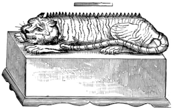
 When putting the car in place in the garage you must also maneuver carefully. The main thing is that...") Methods to get to the right place in a garage
Methods to get to the right place in a garage
When putting the car in place in the garage you must also maneuver carefully. The main thing is that you get in your place and as best you can. Too much brio results in broken walls and bent mudguards. If it makes you nervous, this twisting back and forth, feel free to leave it to someone else. It is not everyone's job and it is precisely with this shunting that small causes can have major consequences. [Translated online from the Dutch ] When overtaking a tram, also pay attention to the possibility that someone will jump in front of or ...") Overtaking a tram
Overtaking a tram
When overtaking a tram, also pay attention to the possibility that someone will jump in front of or from the tram. Giving a good signal and leaving as much road width as possible between the tram and your car is required. To catch up with a steam tram that hurls its plume over the road, and you it obstructs the view, it is advisable to wait until the wind chases away the steam. For the distance required to overtake a fast-moving vehicle such as a tram is too long, that the chance would not become too great that, in time, it would take to catch up with the plume of steam and drive through it. , in the meantime, a road obstruction would arise from the other side, which you would not have been able to see approaching. If you come across such a vehicle, moderate your speed so that you can stop vehicles suddenly emerging from that plume of steam. Give a strong signaland if necessary, stop the car on the right side of the road, until the tram has passed. Because then you have the most certainty, because then only a vehicle moving faster or as fast as the tram can cause danger. And this danger can be averted by giving a signal and keeping the right side of the road well. [Translated online from the Dutch ] When you stop in a street, don't forget to reach out first, as a sign for the vehicle following you....") Parking
Parking
When you stop in a street, don't forget to reach out first, as a sign for the vehicle following you. Place your car neatly along the sidewalk, not crooked or in such a way that traffic is obstructed by it. You must intervene two vehicles or cars get into the car, then drive a little further, and then reverse between the cars. Do not drive straight over to the left side of the street, against the traffic, but drive to the right and then turn along the direction of the traffic, until you are in front of the house, where you want to be. [Translated online from the Dutch ] It is also important to know, if you have to go through or along somewhere close with your car, what...") Room to pass
Room to pass
It is also important to know, if you have to go through or along somewhere close with your car, what width you need. That can become such a certainty for you that it will look like virtuosity to the uninitiated. It's a matter of routine, of course, but it can be extremely practiced. It must be started with calculating the extreme points of the fenders. Later on, even this aid is often redundant. The best way to learn this is to place two blocks of wood on the ground, or to drive two posts, which are measured just the width of the wagon apart. Riding on that is the means of learning to estimate a narrow passage. Is the width wide enough to pass, but what When measured tight, keep flat on the side of the traffic obstruction, which is on your and steering wheel side. After all, here you can see exactly how close you can get without the risk of a collision. The other side will then be free of itself. [Translated online from the Dutch ] If you have to take a side road on the right, keep your arm stretched out in horizontal direction o...") Turn Signal
Turn Signal
If you have to take a side road on the right, keep your arm stretched out in horizontal direction outside the car. [Translated online from the Dutch ] With an open torpedo, the stop signal can also be given by sticking the arm straight up. In any case...") Stop Signal
Stop Signal
With an open torpedo, the stop signal can also be given by sticking the arm straight up. In any case, account must then be taken of the somewhat higher rear of the car, or of the possibility that the passengers behind are masking the movement of the arm. [Translated online from the Dutch ] Swerving at intersections") Swerving at intersections
Swerving at intersections
Swerving at intersections Firstly, in the bends. Great tram cars, especially on narrow track, there are the annoying habit, no...") Cars and Trams
Cars and Trams
Firstly, in the bends. Great tram cars, especially on narrow track, there are the annoying habit, not far off the path of the rails to swing, including the cars of the Amsterdam-Haarlem-Zandvoort-line, the ESM Guard is in such a bend on one approaching tram, or does one want passing in the bend, a car runs the risk of being crushed or at least damaged between the rails and the curb, by the swinging front or rear upper part of the car. [Translated online from the Dutch ] (1491 visits) Beech C-45 (F-2)
Front Sid...") Beech C-45 (F-2)
Beech C-45 (F-2)
Beech C-45 (F-2) Front Side Perspective Bottom Top Beech AT-11
Front Side
Perspective
Bottom ...") Beech AT-11
Beech AT-11
Beech AT-11 Front Side Perspective Bottom Top Beech AT-10
Front Side
Perspective
Bottom ...") Beech AT-10
Beech AT-10
Beech AT-10 Front Side Perspective Bottom Top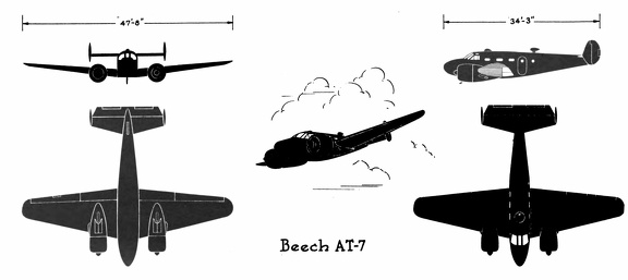 Beech AT-7
Beech AT-7 Front Side Perspective Bottom Top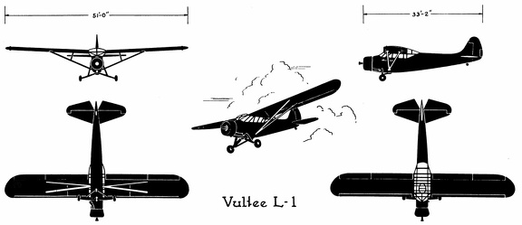 Vultee L-1
Vultee L-1 Front Side Perspective Bottom Top Vultee BT-15
Vultee BT-15 Front Side Perspective Bottom Top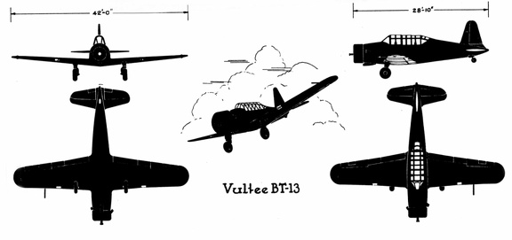 Vultee BT-13
Vultee BT-13 Front Side Perspective Bottom Top Vultee A-31
Front Side
...") Vultee A-31
Vultee A-31
Vultee A-31 Front Side Perspective Bottom Top Stearman PT-17 & 18
Front ...") Stearman PT-17 &18
Stearman PT-17 &18
Stearman PT-17 & 18 Front Side Perspective Bottom Top Ryan PT-22
Front Side
...") Ryan PT-22
Ryan PT-22
Ryan PT-22 Front Side Perspective Bottom Top Republic P-47B
Front Side ...") Republic P-47B
Republic P-47B
Republic P-47B Front Side Perspective Bottom Top Republic P43-A
Front Side ...") Republic P43-A
Republic P43-A
Republic P43-A Front Side Perspective Bottom Top Republic P-35
Front Side
...") Republic P-35
Republic P-35
Republic P-35 Front Side Perspective Bottom Top Republic AT-12
Front Side ...") Republic AT-12
Republic AT-12
Republic AT-12 Front Side Perspective Bottom Top Northrop A-17
Front Side
...") Northrop A-17
Northrop A-17
Northrop A-17 Front Side Perspective Bottom Top North American P-51
Front ...") North American P-51
North American P-51
North American P-51 Front Side Perspective Bottom Top North American O-47A & B
Front &...") North American O-47A& B
North American O-47A& B
North American O-47A & B Front Side Perspective Bottom Top North American B-25 C & D
Front ...") North American B-25 C & D
North American B-25 C & D
North American B-25 C & D Front Side Perspective Bottom Top North American AT-6A
Front  ...") North American AT-6A
North American AT-6A
North American AT-6A Front Side Perspective Bottom Top Martin B-26 B& C
Front Sid...") Martin B-26 B& C
Martin B-26 B& C
Martin B-26 B& C Front Side Perspective Bottom Top Martin B-10B
Front Side
...") Martin B-10B
Martin B-10B
Martin B-10B Front Side Perspective Bottom Top Martin A-30
Front Side
...") Martin A-30
Martin A-30
Martin A-30 Front Side Perspective Bottom Top Lockheed P-38D&E
Front Sid...") Lockheed P-38D&E
Lockheed P-38D&E
Lockheed P-38D&E Front Side Perspective Bottom Top Lockheed C60-A
Front Side ...") Lockheed C60-A
Lockheed C60-A
Lockheed C60-A Front Side Perspective Bottom Top Lockheed C-40A
Front Side ...") Lockheed C-40A
Lockheed C-40A
Lockheed C-40A Front Side Perspective Bottom Top Lockheed A-29&A
Front Side...") Lockheed A-29&A
Lockheed A-29&A
Lockheed A-29&A Front Side Perspective Bottom Top Grumman OA-9
Front Side
...") Grumman OA-9
Grumman OA-9
Grumman OA-9 Front Side Perspective Bottom Top Fairchild PT-19
Front Side...") Fairchild PT-19
Fairchild PT-19
Fairchild PT-19 Front Side Perspective Bottom Top