


 Fifty years later witnessed the full development of Mr. Bell’s ideal in the Columba, then as now t...") “Columba,” famous Clyde river steamer, 1875
“Columba,” famous Clyde river steamer, 1875
Fifty years later witnessed the full development of Mr. Bell’s ideal in the Columba, then as now the largest river steamer ever seen on the Clyde, and the swiftest. The Columba is built of steel, is 316 feet long and 50 feet wide. She has two oscillating engines of 220 horse-power, and attains a speed of twenty-two miles an hour. Her route is from Glasgow to Ardrishaig and back, daily in summer, when she carries from 2,000 to 3,000 persons through some of the finest scenery in Scotland. She is provided with steam machinery for steering and warping her into the piers, and with other modern appliances that make her as handy as a steam yacht. She resembles a little floating town, with shops and post-office where you can procure money orders and despatch telegrams And what is the Columba after all but an enlarged and perfected reproduction of Bell’s Comet! The Zulus, or more correctly the Amazulus, take the front `rank` amongst the native tribes of the Af...") Zulu Marimba
Zulu Marimba
The Zulus, or more correctly the Amazulus, take the front `rank` amongst the native tribes of the African continent. Their code of laws, military arrangements, and orderly settlements resemble those of civilised nations at many points. Their dances are a national feature, and a great company of young warriors performing a solemn war dance is a most impressive sight. One of their chief instruments is the 'Marimba' or 'Tyanbilo,' a form of harmonium. The keys are bars of wood called Intyari, of graduated size. These are suspended by strings from a light wooden frame, either resting on the ground, or hung round the neck of the player. Between every two keys is a wooden bar crossing the centre bar to which the keys are attached. On each key two shells of the fruit known as the Strychnos McKenzie, or Kaffir Orange, are placed as resonators, one large and one small. The use of resonators is to increase and deepen the sound. The Marimba is played with drum-sticks of rubber, and the tone is good and powerful. Zenith Telescope constructed for the International Stations at Mizusawa, Carloforte, Gaithersburg an...") Zenith Telescope
Zenith Telescope
Zenith Telescope constructed for the International Stations at Mizusawa, Carloforte, Gaithersburg and Ukiah, by Hermann Wanschaff, Berlin.") Yale 1910
Yale 1910 When the Wrights had built an engine, there was still the question how they should make it drive the...") Wright Motor and Propellers
Wright Motor and Propellers
When the Wrights had built an engine, there was still the question how they should make it drive their aeroplane. They inclined naturally to the idea of an aerial propeller. Two courses lay open to them; they could fit one propeller running at high speed and coupled directly to the motor, or they could use two propellers, revolving at slower speed and geared in some way to the engine. They decided upon the latter course, placing two propellers behind the main planes of their machine and driving them from the engine by means of light chains, these running in guiding tubes. This system of propulsion is shown. A. Motor; B. Gear-wheels upon motor crank-shaft; C.C. Tubes carrying driving chains; D.D. Sprocket-wheels over which chains pass; E.E. Propellers. A. Biplane; B. Rail; C. Rope passing from the aeroplane round the pulley-wheel (D.) and thence to th...") Wright Launching Rail
Wright Launching Rail
A. Biplane; B. Rail; C. Rope passing from the aeroplane round the pulley-wheel (D.) and thence to the derrick (E.); (F.) Falling weight. Details of propulsion and control being arranged, there remained the question of how the machine should be launched into the air. In their gliding tests, it will be remembered, the Wrights employed assistants, who held the machine by the wing-tips and ran forward with it. But the weight of the power-driven machine, and its greater size, prevented such a plan as this. They decided, therefore, to launch it from a rail, and to aid its forward speed, at the moment of taking the air, by a derrick and a falling weight. They found that a slight curve or camber in the wing section would cause the moving air to travel fa...") Wright Brothers' Wind tunnel
Wright Brothers' Wind tunnel
They found that a slight curve or camber in the wing section would cause the moving air to travel farther over the top of the wing surface than along the under side. This made the air pressure greater under the wing, gave a suction effect above the wing, and caused it to rise, creating lift. They discovered that a wing section of the proper camber would counteract the weight of gravity. Thus, a wing must be so designed that, with a certain amount of air flowing around it, it would lift a certain weight. They also discovered that air flow against any surface attached to the wing would cause a resistance or drag. Hundreds of experiments in their wind tunnel with various types of wing shapes gave the Wrights a series of tables from which to design a wing that would create the lift for a designed weight. Out in Dayton, Ohio, there were two small brothers, who dreamed, as countless other children before ...") Wright Brothers' Bicycle shop
Wright Brothers' Bicycle shop
Out in Dayton, Ohio, there were two small brothers, who dreamed, as countless other children before them had dreamed, of flying like birds through the air. Their dreams were heightened by a small toy given to them by their father, the pastor of a local church. This toy was to lead to an idea which had a profound effect on the world. You would probably call it a flying propeller. It consisted of a wooden propeller which slipped over a notched stick. By placing a finger against the propeller and rapidly pushing it up the notched stick, the propeller was made to whirl up off the end of the stick and fly into the air. The brothers, young as they were, never quite forgot this little toy as they continued to dream of flying like birds through the air. Though the brothers continued to dream of flying, they were not the kind of lads who spent all their time in dreaming. They made kites which flew a little better and a little higher than those made by the other boys in the neighborhood. They built a press to print their own little newspaper, and they dabbled in woodcuts. To carve out porch posts for their father’s home they built an eight-foot wood-turning lathe. Indeed, they were the sort of boys who caused the neighbors to say, “What will they think of next?” The brothers knew that if they ever wanted to see their dreams come true they must earn their own capital. In the early nineties America was in the midst of the bicycle craze. Everyone who could possibly afford to do so owned a bicycle of some sort and belonged to a cycle club. Being mechanically minded, the brothers did the logical thing. They set themselves up in a small bicycle shop in Dayton, next door to their home. The bicycle shop in Dayton prospered, for the brothers were careful and expert mechanics, and cyclists in need of repairs made their way to the Wright Brothers’ shop. By 1903 the Wright Brothers were ready to build a powered man-carrying flying machine. Their experim...") Wright Brothers first powered airplane
Wright Brothers first powered airplane
By 1903 the Wright Brothers were ready to build a powered man-carrying flying machine. Their experiments had shown them just how much moving air was necessary to create lift in such a machine. To create the needed thrust, an engine having eight horsepower and weighing not over 200 pounds had to be fitted into the machine. Such an engine was not available, so the Wrights built one in their shop at Dayton, Ohio. They were ready to ship their airplane to Kitty Hawk, N. C., in the fall of 1903. The Wright Brothers were not only inspired mechanics (as many people still believe today) but seriou...") Wright Brotherrs wind tunnel
Wright Brotherrs wind tunnel
The Wright Brothers were not only inspired mechanics (as many people still believe today) but serious scientists, working along the soundest lines. In their keen desire to know what air pressure on wings really was, they cleared a corner of their bicycle shop and built a small wind tunnel with spare lumber and an old electric fan. They built small wing sections of various shapes and experimented with them in their wind tunnel. The electric fan was used to create the moving air around the wing section. By attaching the wing sections to a supporting frame and connecting the frame with a pointer and dial, they were able to keep a record of the effect of moving air on each experimental wing section. Through their wind tunnel research the Wright Brothers discovered the four forces that control all heavier-than-air flight: lift, thrust, weight, and drag.") Workman fashioning a spectacle lens
Workman fashioning a spectacle lens") Woods Electric Tonneau
Woods Electric Tonneau") Woods Brougham
Woods Brougham Woman using leeches, 17th century. (From Guillaume van den Bossche, Historica Medica, Brussels, 1639...") Woman using leeches
Woman using leeches
Woman using leeches, 17th century. (From Guillaume van den Bossche, Historica Medica, Brussels, 1639.) Wolfe, Model A, 24 H.P. H. E. Wilcox Motor Car Company, Minneapolis, Minn.
PRICE: $1,800
BO...") Wolfe, Model A, 24 H.P
Wolfe, Model A, 24 H.P
Wolfe, Model A, 24 H.P. H. E. Wilcox Motor Car Company, Minneapolis, Minn. PRICE: $1,800 BODY: Side entrance, rear seat removable SEATS: 5 persons WEIGHT: 1,900 pounds WHEEL-BASE: 108 inches TREAD: 56 inches TIRES, FRONT: 34 × 3½ inches TIRES, REAR: 34 × 3½ inches STEERING: Worm and sector BRAKES: On rear hubs SPRINGS: Full elliptic FRAME: Pressed steel BORE: 4 in.; STROKE: 4 in. CYLINDERS: 4 vertical, tandem MOTOR SUSPENSION: On sub-frame COOLING: Air IGNITION: Jump spark CURRENT SUPPLY: Battery CARBURETER: Float-feed LUBRICATION: Mechanical force feed MOTOR-CONTROL: Spark and throttle CLUTCH: Cone CHANGE GEAR: Sliding type SPEEDS: 3 forward and reverse CHANGE-GEAR CONTROL: Side lever DRIVE: Side chain NOTE: Runabout body fitted to above chassis for a list of $1,700. Light delivery body also furnished on order.") White Steamer
White Steamer Whistling bouy
Less picturesque than lighthouses and lightships, and with far less of human inter...") Whistling bouy
Whistling bouy
Whistling bouy Less picturesque than lighthouses and lightships, and with far less of human interest about them, are the buoys of various sorts of which the Lighthouse Board has more than one thousand in place, and under constant supervision. Yet, among the sailor's safeguards, they `rank` near the head. They point out for him the tortuous pathway into different harbors; with clanging bell or dismal whistle, they warn him away from menacing shallows and sunken wrecks. The resources of science and inventive genius have been drawn upon to devise ways for making them more effective. At night they shine with electric lights fed from a submarine cable, or with steady gas drawn from a reservoir that needs refilling only three or four times a year. If sound is to be trusted rather than light, recourse is had to a bell-buoy which tolls mournfully as the waves toss it about above the danger spot, or to a whistling buoy which toots unceasingly a locomotive whistle, with air compressed by the Page 355action of the waves. The whistling buoy is the giant of his family, for the necessity for providing a heavy charge of compressed air compels the attachment to the buoy of a tube thirty-two feet or more deep, which reaches straight down into the water. The sea rising and falling in this, as the buoy tosses on the waves, acts as a sort of piston, driving out the air through the whistle, as the water rises, admitting more air as it falls. Whale sending boat flying
While the right whale usually takes the steel sullenly, and dies like a...") Whale sending boat flying
Whale sending boat flying
Whale sending boat flying While the right whale usually takes the steel sullenly, and dies like an overgrown seal, the cachalot fights fiercely, now diving with such a rush that he has been known to break his jaw by the fury with which he strikes the bottom at the depth of 200 fathoms; now raising his enormous bulk in air, to fall with an all-obliterating crash upon the boat which holds his tormentors, or sending boat and men flying into the air with a furious blow of his gristly flukes, or turning on his back and crunching his assailants between his cavernous jaws. Wet cupping for a headache. (From Frederik Dekkers, Exercitationes Practicae Circa Medendi Methodum,...") Wet Cupping for a headache
Wet Cupping for a headache
Wet cupping for a headache. (From Frederik Dekkers, Exercitationes Practicae Circa Medendi Methodum, Leyden, 1694.) In 1866, two decades after the flight of Stringfellow’s monoplane, Mr. F. H. Wenham, another Engli...") Wenham’s aëroplane, 1866
Wenham’s aëroplane, 1866
In 1866, two decades after the flight of Stringfellow’s monoplane, Mr. F. H. Wenham, another Englishman illustrious in the annals of aëronautics, patented the multiplane; that is, an aëroplane comprising two or more superposed surfaces. This proved to be a valuable contribution to the art of aviation, and continues in use at the present time. The device furnished an increase of sustaining surface without enlargement of the ground plan. It moreover lends itself conveniently to a strong and simple trussing of the surfaces. Some designers protest that superposed surfaces blanket one another; but the advantages just named seem amply to compensate for this objectionable feature. If the surfaces be properly spaced, very little interference is found; moreover, any blanketing that may occur diminishes the drift as well as the lift,[20] though not necessarily in the same proportion. Wenham’s aëroplane is illustrated. The rider lies underneath the multiple wings, so as to diminish the resistance to progression through the air. The apparatus could thus be used as an aërial toboggan for coasting down the atmosphere. To prolong the flights two flappers actuated by a treadle were to be employed, their ends being hinged at a point above the operator’s back. Though the device was patented, no very serious efforts were made to operate it practically. Once, indeed, the inventor took his glider to a meadow and mounted it, during a lull in the evening wind, but soon a gust caught him up, carried him some distance from the ground and toppled him over sidewise, breaking some of the surfaces. The machine disclosed some good working principles; but it was inadequately ruddered, and too feebly constructed, to weather the buffets of the prevailing ground currents.
Patent Iron Suspension Railroad Bridge.
The undersigned would inform the officers of Railroads ...") Wendell Bollmans Patent Bridge
Wendell Bollmans Patent Bridge
Patent Iron Suspension Railroad Bridge. The undersigned would inform the officers of Railroads and others, that he is prepared to furnish Drawings and Estimates for Bridges, Roofs, etc., on the plan of Bollman’s Patent. The performance of these bridges, some of which have been in use for six years, has given entire satisfaction. Their simplicity of construction renders repairs easy and cheap, and by a peculiar connection of the Main and Panel Rods at the bottom of the Posts, all danger from the effects of expansion, which has heretofore been the chief objection to Iron Bridges, is entirely removed. J. H. TEGMEYER, Baltimore, Md. The Waterfront of New York") Waterfront
Waterfront
The Waterfront of New York We must remember that travelling was no such simple and easy matter then as it is now. As the plante...") Washington's Coach
Washington's Coach
We must remember that travelling was no such simple and easy matter then as it is now. As the planters in Virginia usually lived on the banks of one of the many rivers, the simplest method of travel was by boat, up or down stream. There were cross-country roads, but these at best were rough, and sometimes full of roots and stumps. Often they were nothing more than forest paths. In trying to follow such roads the traveler at times lost his way and occasionally had to spend a night in the woods. But with even such makeshifts for roads, the planter had his lumbering old coach to which, on state occasions, he harnessed six horses and drove in great style.") Walther pistol
Walther pistol Waltham-Orient, Model B R., 4 H.P. Waltham Mfg. Co., Waltham, Mass.
PRICE: $400
BODY: Runab...") Waltham-Orient, Model B R., 4 H.P
Waltham-Orient, Model B R., 4 H.P
Waltham-Orient, Model B R., 4 H.P. Waltham Mfg. Co., Waltham, Mass. PRICE: $400 BODY: Runabout SEATS: 2 persons WEIGHT: 600 pounds WHEEL-BASE: 80 inches TREAD: 42 inches TIRES, FRONT: 26 × 2½ in. TIRES, REAR: 26 × 2½ in. STEERING: Tiller BRAKES: On rear hubs SPRINGS: Elliptical front and rear FRAME: Wood BORE: 3¼ in.; STROKE: 4¼ in. CYLINDERS: One in back VALVE ARRANGEMENT: Automatic inlet; mechanical exhaust MOTOR SUSPENSION: Rear on side members of frame COOLING: Air IGNITION: Jump spark CURRENT SUPPLY: Dry battery CARBURETER: Orient LUBRICATION: Oil pump MOTOR-CONTROL: Throttle and spark CLUTCH: Friction CHANGE GEAR: Friction SPEEDS: 5 forward, 2 reverse CHANGE-GEAR CONTROL: Side lever DRIVE: Friction drive NOTE: Furnished with 2 cylinder motor for $50 extra. W. D. Hooper’s patent cupping apparatus with tubular blades. (From patent specifications, U.S. pat...") W. D. Hooper’s patent cupping apparatus with tubular blades
W. D. Hooper’s patent cupping apparatus with tubular blades
W. D. Hooper’s patent cupping apparatus with tubular blades. (From patent specifications, U.S. patent no. 68985.)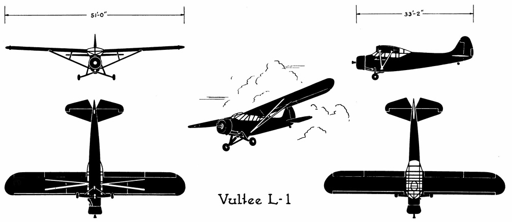 Vultee L-1
Vultee L-1 Front Side Perspective Bottom Top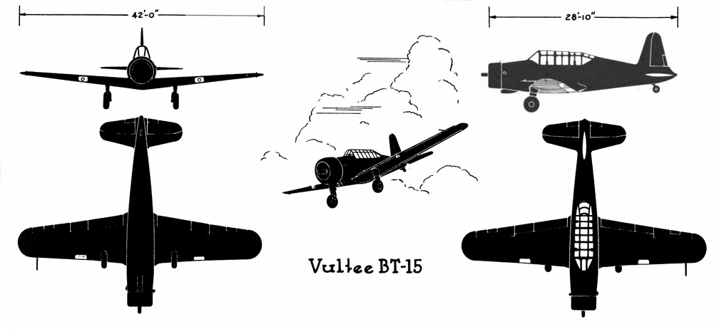 Vultee BT-15
Vultee BT-15 Front Side Perspective Bottom Top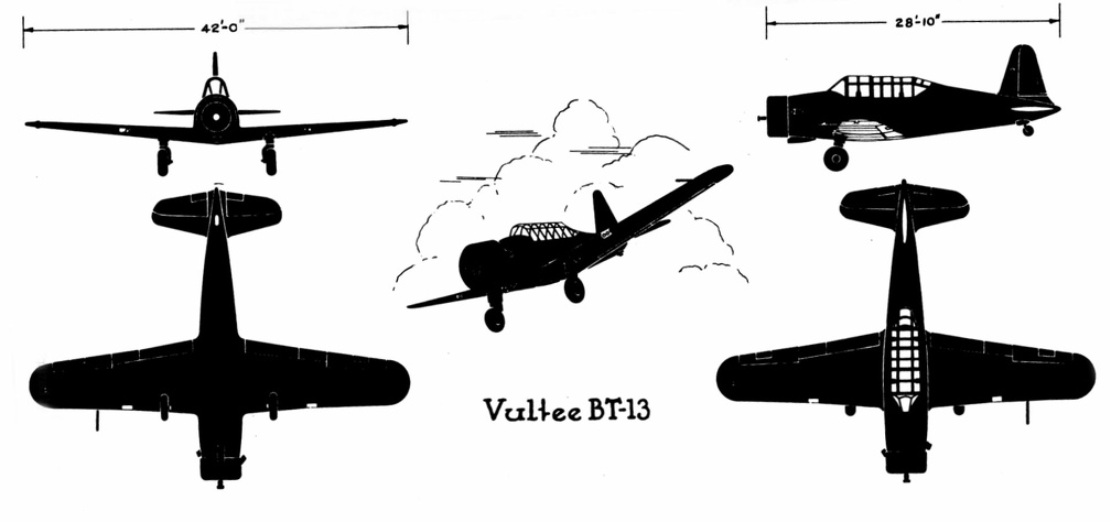 Vultee BT-13
Vultee BT-13 Front Side Perspective Bottom Top Vultee A-31
Front Side
...") Vultee A-31
Vultee A-31
Vultee A-31 Front Side Perspective Bottom Top In the launching of gliders, some French experimenters showed ingenuity. The brothers Voisin, for in...") Voisin Glider towed by a motor-car
Voisin Glider towed by a motor-car
In the launching of gliders, some French experimenters showed ingenuity. The brothers Voisin, for instance, who played a prominent part in the early tests in France, adopted the plan illustrated. The gilder was towed by a motor-car across an open stretch of ground; then, when its speed was sufficient for the planes to lift, it rose and flew behind the car like a kite. A form of glider, mounted upon hollow wooden floats—anticipating the sea-plane of to-day—and tow...") Voisin Glider on the river Seine
Voisin Glider on the river Seine
A form of glider, mounted upon hollow wooden floats—anticipating the sea-plane of to-day—and towed upon the river Seine by a motor-boat. This gilder also, when its speed became sufficient, rose into the air. In the construction of the machine, a biplane, one notes resemblances to the method of the Wrights; and yet generally the craft is dissimilar. Virginal
The instruments has mtal strings, one for each tone, whiched are twanged by means of smal...") Virginal
Virginal
Virginal The instruments has mtal strings, one for each tone, whiched are twanged by means of small portions of quill, attached to slips of wood called "jacks" and provided with thin metal springs. German. About 1600 Viola di Bardone
The finger-board is carved in open fret-work terminating in three lions' heads; ...") Viola di Bardone
Viola di Bardone
Viola di Bardone The finger-board is carved in open fret-work terminating in three lions' heads; above the bridge are two figures of negrose, carved and gilt. German 1686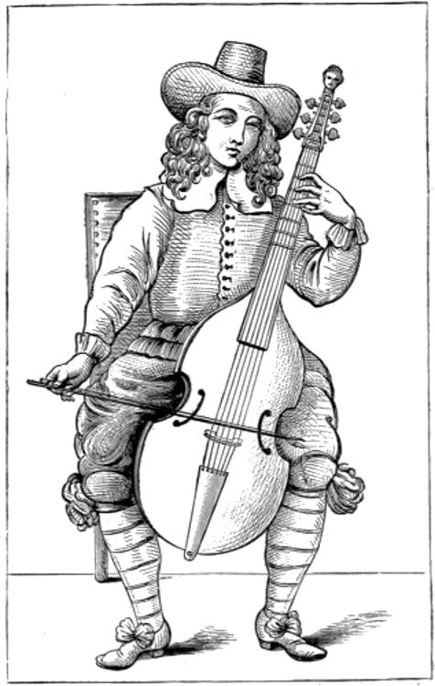 Viola da gamba
The player on the viola da gamba, shown in the engraving, is a reduced copy of an illustration in “The Division Violist,” London, 1659. It shows exactly how the frets were regulated, and how the bow was held. The most popular instruments played with a bow, at that time, were the treble-viol, the tenor-viol, and the bass-viol. It was usual for viol players to have “a chest of viols,” a case containing four or more viols, of different sizes. Thus, Thomas Mace in his directions for the use of the viol, “Musick’s Monument” 1676, remarks, “Your best provision, and most complete, will be a good chest of viols, six in number, viz., two basses, two tenors, and two trebles, all truly and proportionably suited.” The violist, to be properly furnished with his requirements, had therefore 119to supply himself with a larger stock of instruments than the violinist of the present day. The woodcut represents a very beautiful vielle; French, of about 1550, with monograms of Henry II. T...") Vielle
Vielle
The woodcut represents a very beautiful vielle; French, of about 1550, with monograms of Henry II. This is at South Kensington. The contrivance of placing a string or two at the side of the finger-board is evidently very old, and was also gradually adopted on other instruments of the violin class of a somewhat later period than that of the vielle; for instance, on the lira di braccio of the Italians. It was likewise adopted on the lute, to obtain a fuller power in the bass; and hence arose the theorbo, the archlute, and other varieties of the old lute. The earliest of Da Vinci’s aëronautic ideas to be practically realized was the parachute. The exa...") Veranzio’s parachute
Veranzio’s parachute
The earliest of Da Vinci’s aëronautic ideas to be practically realized was the parachute. The exact date of its first employment is not exactly known. In the year 1617 Fauste Veranzio published in Venice a good technical description of the construction and operation of the parachute, accompanied by a clear illustration. The article upon the Velocipede in the \" American Encyclopedia,\" commences by giving the well-known ...") Velocipedes
Velocipedes
The article upon the Velocipede in the " American Encyclopedia," commences by giving the well-known derivation of the word from the Latin velox, swift, and pes, a foot, and defines it as a carriage, by means of which the rider propels himself along the ground, and states that it was invented at Manheim. We present a bicycle for ladies, lately invented and patented by Messrs. Pickering & Davis of New Yo...") Velocipede for Ladies
Velocipede for Ladies
We present a bicycle for ladies, lately invented and patented by Messrs. Pickering & Davis of New York City. It will be seen that the reach or frame, instead of forming a nearly straight line from the front swivel to the hind axle, follows the curve of the front wheel until it reaches a line nearly as low as the hind axle when it runs horizontally to that point of the hind wheel. The two wheels being separated three or four inches, allow of an upright rod being secured to the reach; around this is a spiral spring, on which a comfortable, cane-seated, willow-backed chair is placed. This machine, with a moderate-sized wheel (of thirty to thirty-three inches), will allow being driven with a great deal of comfort and all the advantages of the two-wheel veloce. In mounting, a lady has to step over the reach, at a point only twelve inches from the floor, the height of an ordinary step in a flight of stairs.") Velocipede
Velocipede The German-developed V-1 was an automatically controlled pilotless aircraft for use against Allied c...") V1 Rocket
V1 Rocket
The German-developed V-1 was an automatically controlled pilotless aircraft for use against Allied cities during World War II. The missile was launched from ground ramps. Once in the air, automatic controls on board the craft took over. The V-1 climbed to a predetermined altitude, followed a compass course, and dove to the ground after a preset distance had been covered. This mid-wing monoplane was powered by a unique pulsejet engine above the rear portion of the fuselage. The relatively low speed of the missile made it easy prey for antiaircraft guns or fighters.") Using Bells phone
Using Bells phone This instrument was meant to improve on the cross staff. One man held it, when it was supposed to ha...") Using an Astrolabe
Using an Astrolabe
This instrument was meant to improve on the cross staff. One man held it, when it was supposed to hang with the horizon line horizontal. Another man sighted at the sun or the stars, and a third read and recorded the angle. Needless to say the instrument was very inaccurate. This apparatus consists of a movable plate marked with compass bearings, set in a stand. The observe...") Using a Pelorus
Using a Pelorus
This apparatus consists of a movable plate marked with compass bearings, set in a stand. The observer sets the plate to correspond to the standard compass, and then sights across it in determining the compass bearings of points ashore from which he wishes to learn his exact position. This crude instrument was used in an attempt to work out problems in latitude. After holding one end...") Using a Cross Staff
Using a Cross Staff
This crude instrument was used in an attempt to work out problems in latitude. After holding one end of the staff to the eye and sliding the cross staff along until the observer sighted over one end at the sun and under the other at the horizon, the instrument was placed on a circle marked in degrees, and the angle was determined. Ky, is the Key in its resting position.
c, wherever found, represents a cushion of felt or soft l...") Upright Piano Action
Upright Piano Action
Ky, is the Key in its resting position. c, wherever found, represents a cushion of felt or soft leather upon which the different parts of the action rest or come in contact with each other. Their purpose, as is readily seen, is that of rendering the action noiseless and easy of operation. Bnc R, shows the end of the balance rail, extending the entire length of the keyboard. B P, is the balance pin. This is a perfectly round pin driven firmly in the balance rail. The bottom of the hole in the key fits closely around the balance pin; at the top, it is the shape of a mortise, parallel with the key, which allows the key to move only in the direction intended. The mortise in the wooden cap on top of the key at this point is lined with bushing cloth which holds the key in position laterally, and prevents looseness and rattling, yet allows the key to move easily. Upright action showing lost-motion device, metallic regulating rail support, capstan screw, jack reg...") Upright action showing lost-motion device
Upright action showing lost-motion device
Upright action showing lost-motion device, metallic regulating rail support, capstan screw, jack regulating rail and metallic action brackets. 34. Hammer-rail lifter-wire. 35. Hammer-rail swing-lever. 36. Hammer-rail lifter rod. 37. Lifter-rod lever. 38. Compensation-lever. 39. Capstan-screw. 40. Rail for limiting return movement of jack. 41. Metallic regulating rail support. the figure shows the recording anemometer for speed and double direction constructed by the writer i...") Universal anemograph
Universal anemograph
the figure shows the recording anemometer for speed and double direction constructed by the writer in 1892. A large weather vane was firmly strapped to a vertical pipe which turned freely on ball bearings and, by means of a small crank actuating a chronograph pencil, recorded its fluctuations on a long sheet of paper winding on the drum from a roll behind. On top of the pipe and about fifteen feet from the ground, was mounted a carefully balanced horizontal vane, from which a fine steel wire ran down the axis of the pipe to a fixed pulley, thence to a second recording pencil. A third pencil recorded the beats of a pendulum, thus standardizing the speed of the paper. A fourth pencil, not shown, was designed to record the turns of an anemometer mounted near the top of the pipe. The records of the wind speed thus secured are omitted for lack of standardization, as the experiments were prematurely terminated. United States Carriage model of 1896") United States Carriage model of 1896
United States Carriage model of 1896
United States Carriage model of 1896 Conversion from Vibration to Voice Currents.
The figure illustrates a simple machine adapted to t...") Type of Magneto Telephone
Type of Magneto Telephone
Conversion from Vibration to Voice Currents. The figure illustrates a simple machine adapted to translate motion of a diaphragm into an alternating electrical current. The device is merely one form of magneto telephone chosen to illustrate the point of immediate conversion. 1 is a diaphragm adapted to vibrate in response to the sounds reaching it. 2 is a permanent magnet and 3 is its armature. The armature is in contact with one pole of the permanent magnet and nearly in contact with the other. The effort of the armature to touch the pole it nearly touches places the diaphragm under tension. The free arm of the magnet is surrounded by a coil 4, whose ends extend to form the line.") Tycho Brahe's House and Observatory
Tycho Brahe's House and Observatory Two early types of liquid-fuel, rocket motors. Left, the original ARS motor; right, a four-nozzle mo...") Two early types of liquid-fuel, rocket motors.
Two early types of liquid-fuel, rocket motors.
Two early types of liquid-fuel, rocket motors. Left, the original ARS motor; right, a four-nozzle motor for ARS No. 4 rocket. Thrust stud for fastening to rocket Blast chamber Fuel feed Oxygen feed Nozzle Water jacket Nozzles Thrust and fuel column attached to rocket Fuel feed The string telephones which for several years have been flooding the boulevards and the streets of t...") Twine phones
Twine phones
The string telephones which for several years have been flooding the boulevards and the streets of the different cities of Europe, and whose invention dates back, as we have seen, to the year 1667, are very interesting apparatuses by them themselves, and we are astonished that they did not appear rather in the physics cabinets. They consist of cylindrical-conical tubes of metal or cardboard, one end of which is closed by a stretched membrane of parchment, in the center of which is fixed by a knot the string or cord intended to bring them together. When two tubes of this kind are thus joined together and that the wire is tight, as shown, it suffices for a person to apply one of these tubes against the ear and for another person to speak very close to the opening of the other tube, so that all the words spoken by the latter are immediately transmitted to the other, and one can even converse in this manner in an almost low voice.") Twenty-Passenger Break for the World's Fair
Twenty-Passenger Break for the World's Fair If you have to take a side road on the right, keep your arm stretched out in horizontal direction o...") Turn Signal
Turn Signal
If you have to take a side road on the right, keep your arm stretched out in horizontal direction outside the car. [Translated online from the Dutch ]") Tudor Knox
Tudor Knox") Trepied
Trepied The trebuchet was another war machine used extensively during the Middle Ages. Essentially, it was a...") trebuchet
trebuchet
The trebuchet was another war machine used extensively during the Middle Ages. Essentially, it was a seesaw. Weights on the short arm swung the long throwing arm. There needs to be an equipment of spare machines also; and a number of travelling workshops with ski...") Travelling workshop for the repair of military aeroplanes
Travelling workshop for the repair of military aeroplanes
There needs to be an equipment of spare machines also; and a number of travelling workshops with skilled engineers, which can be rushed from place to place for the repair of damaged craft. A sketch of one of these workshops on wheels, which are vital to the organisation, is seen in the figure, 1750 (621 visits)") Travelling Posting Carriage (2), 1750
Travelling Posting Carriage (2), 1750