


« 2020
2022 »
January
February
March
April
May
June
July
August
September
October
November
December
All

 The Pedrail, as it has been named, signifies a rail moving on feet. Mr. Diplock, observing that a ho...") Pedrail
Pedrail
The Pedrail, as it has been named, signifies a rail moving on feet. Mr. Diplock, observing that a horse has for its weight a tractive force much in excess of the traction-engine, took a hint from nature, and conceived the idea of copying the horse's foot action. The reader must not imagine that here is a return to the abortive and rather ludicrous attempts at a walking locomotive made many years ago, when some engineers considered it proper that a railway engine should be propelled by legs. Mr. Diplock's device not merely propels, but also steps, i.e. selects the spot on the ground which shall be the momentary point at which propulsive force shall be exerted.") Fire Engine
Fire Engine An extreme instance of the pedrail's capacity would be afforded by the ascent of a flight of steps ....") Pedrail cimbing stairs
Pedrail cimbing stairs
An extreme instance of the pedrail's capacity would be afforded by the ascent of a flight of steps . In such a case the three "peds" carrying the weight of an axle would not be on the same level. That makes no difference, because the frame merely tilts on its top and bottom pivots, the front of the rail rising to a higher level than the back end, and the back spokes being projected by the rail much further than those in front, so that the engine is simply levered over its rollers up an inclined plane. Similarly, in descending, the front spokes are thrust out the furthest, and the reverse action takes place.") Piano
Piano The Jewish Shophar, a simple ram's horn, a woodcut of which, drawn from an interesting example prese...") Jewish Shophar
Jewish Shophar
The Jewish Shophar, a simple ram's horn, a woodcut of which, drawn from an interesting example preserved at the great Synagogue, Aldgate, London, figures at the end of this Introduction, is the oldest wind instrument in present use in the world. It is first named in the Bible as sounding when the Lord descended upon Mount Sinai, and there seems to be little doubt that it has been continuously used in the Mosaic Service from the time it was established until now. It is sounded in the synagogues at the New Year and on the Fast of the Day of Atonement. The Talmud gives ten reasons for sounding the Shophar at the New Year, which may be summed up as reminding those who hear it of the Creation, Penitence, and the Law, of the Prophets, who were as watchmen blowing trumpets, of the Temple and the Binding of Isaac, of Humility, the gathering together of Israel, the Resurrection, and the day of Judgment, when the trumpet shall sound for all. The embouchure of the Shophar is very difficult, and but three proper tones are usually obtained from it, although in some instances-xiii- higher notes can be got. The short rhythmic flourishes are common, with unimportant differences, to both the German and Portuguese Jews, and consequently date from before their separation.") Royal Mail Coach
Royal Mail Coach") A 'Fischer' Combination Omnibus
A 'Fischer' Combination Omnibus") A type of extemporised motor ambulance favoured by the French and Belgians
A type of extemporised motor ambulance favoured by the French and Belgians") Banked turn on a biplane
Banked turn on a biplane") Frankford arsenal centrifugal fuses
Frankford arsenal centrifugal fuses, 1750 (606 visits)") Travelling Posting Carriage (2), 1750
Travelling Posting Carriage (2), 1750") Travelling Post, 1825-35
Travelling Post, 1825-35") King George IV. in His Pony Phaeton
King George IV. in His Pony Phaeton") Construction of a Monoplane wing
Construction of a Monoplane wing") Block swings free to right of gun
Block swings free to right of gun (647 visits)") London Hackney Cab (Boulnois’ Patent)
London Hackney Cab (Boulnois’ Patent), 1750 (657 visits)") Travelling Posting Carriage (1), 1750
Travelling Posting Carriage (1), 1750") Breech in normal position—closed
Breech in normal position—closed") 36-inch searchlight and controller
36-inch searchlight and controller") An assembled mine
An assembled mine Langley built his plane without much difficulty, but could not find anyone to make an engine large e...") The Aerodrome
The Aerodrome
Langley built his plane without much difficulty, but could not find anyone to make an engine large enough for it. Finally, Charles Manley, an expert engineer, asked for permission to build the engine. Manley’s engine was a five-cylinder, radial gasoline engine that developed 51 horsepower and was far ahead of its time. It was years before American radial engines were used successfully in airplanes. Professor Langley called his machine the Aerodrome, and by October, 1903, the plane was ready for its test flight, with Manley to guide it. The Aerodrome was to be launched from a catapulting platform built on the roof of a houseboat. The houseboat was anchored on the Potomac River near Washington. As it left the platform the machine crashed into the river, and the trial was a dismal failure. The newspapers and the public ridiculed Langley, but he and Manley, who was unhurt in the crash, repaired the machine for another trial. This test took place on December 8, 1903, and again the Aerodrome crashed into the river. Manley once more escaped injury, but Langley and the government were abused by the public for wasting money. Langley was out of money himself, the government could not furnish funds for further trials, so the experiments were ended. The professor, discouraged and brokenhearted, gave up.") rotating crank-catch turned 90°
rotating crank-catch turned 90°") Frankford arsenal 21-second combination fuse
Frankford arsenal 21-second combination fuse") 5 inch R.F. gun and breech mechanism
5 inch R.F. gun and breech mechanism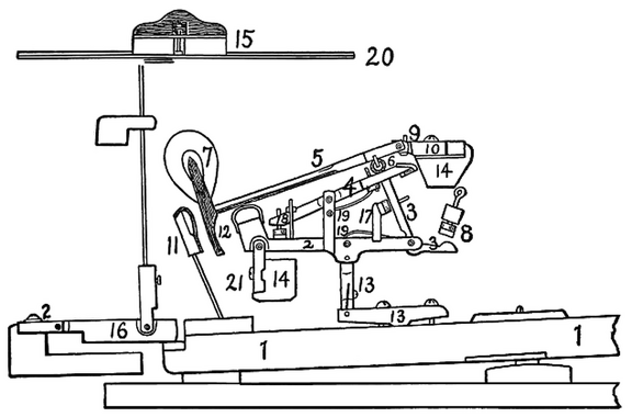 Standard modern American grand action
1. Key. 2. Wippen. 3. Jack. 4. Escapement lever. 5. Hammer-shank. 6. Roller. 7. Hammer-head. 8. Jack-regulating button. 9. Regulating button to limit rise of escapement lever. 10. Hammer-butt. 11. Check. 12. Molded tail of hammer-head to engage with check. 13. Key-rocker and sticker connecting wippen and key. 14. Action-rails. 15. Damper-head. 16. Damper operating device. 17. Device to limit travel of jack. 18. Regulating device for escapement lever. 19. Separate springs for jack and escapement lever. 20. String. 21. Flanges. 1. Key-rocker.
2. Abstract.
3. Abstract-lever.
4. Flange.
5. Action-rail.
6. Wip...") Standard American upright action
Standard American upright action
1. Key-rocker. 2. Abstract. 3. Abstract-lever. 4. Flange. 5. Action-rail. 6. Wippen. 7. Jack. 8. Jack-spring. 9. Check. 10. Check-wire. 11. Bridle-wire. 12. Tip of bridle-tape. 13. Bridle-tape. 14. Back-stop. 15. Regulating rail. 16. Regulating button. 17. Regulating screw. 18. Hammer-butt. 19. Hammer-shank. 20. Hammer-molding. 21. Hammer-head. 22. Hammer-rail. 23. Hammer-butt spring. 24. Hammer-spring rail. 25. Damper-spoon. 26. Damper-lifting rod. 27. Damper-lever. 28. Damper-lever spring. 29. Damper-wire. 30. Damper-block. 31. Damper-head. 32. String. 33. Continuous brass hammer-butt flange. During the Crimean War, Boydell’s traction machine was used to haul open trucks on the road and ac...") The 'Hercules' Traction Engine, as used during the Crimean War
The 'Hercules' Traction Engine, as used during the Crimean War
During the Crimean War, Boydell’s traction machine was used to haul open trucks on the road and across country. Its engine, the “Hercules,” was fitted with a curious arrangement, which, by means of rails attached in six sections to the wheels, enabled it to lay down and take up its own track as it went along.") the block released
the block released") Frankford arsenal time percussion or combination fuse - Model 1900
Frankford arsenal time percussion or combination fuse - Model 1900 A. Continuous bent rim.
B. Wooden struts.
C. Iron shoe holding struts and connecting with iron pla...") Modern method og grand pianoforte case construction
Modern method og grand pianoforte case construction
A. Continuous bent rim. B. Wooden struts. C. Iron shoe holding struts and connecting with iron plate. D. Main beam. Sketch of iron plate for concert grand, showing general arrangement of braces, belly-bridges and sys...") Sketch of iron plate for concert grand
Sketch of iron plate for concert grand
Sketch of iron plate for concert grand, showing general arrangement of braces, belly-bridges and system of bolts for fastening to case. A—B. Hammer line. 1. Body of plate. 2. Bass bridge. 3. Continuous treble bridge. 4. Agraffes. 5. Capo d’astro bar. Plate is cast in one piece and scale is overstrung. Grand pianoforte action with metallic action and damper frames, sostenuto pedal device and hammer ...") Grand pianoforte action with metallic action and damper frames
Grand pianoforte action with metallic action and damper frames
Grand pianoforte action with metallic action and damper frames, sostenuto pedal device and hammer swinging soft pedal attachment. 22. Sostenuto pedal-rod. 23. Attachment to damper-lever engaging with sostenuto pedal-rod. 24. Metallic action and damper-brackets. 25. Hammer swing-rail and cushion. 26. Hammer swing-rail rod. 27. Hammer swing-rail lifter. 28. Lifter-rod. 29. Lost motion compensating levers. 30. Lost motion compensating levers.") 36-inch searchlight and controller
36-inch searchlight and controller") A Krupp motor gun-carrying lorry
A Krupp motor gun-carrying lorry") boat-telephone
boat-telephone") Jonas Chickering’s full solid cast grand metal plate
Jonas Chickering’s full solid cast grand metal plate Upright action showing lost-motion device, metallic regulating rail support, capstan screw, jack reg...") Upright action showing lost-motion device
Upright action showing lost-motion device
Upright action showing lost-motion device, metallic regulating rail support, capstan screw, jack regulating rail and metallic action brackets. 34. Hammer-rail lifter-wire. 35. Hammer-rail swing-lever. 36. Hammer-rail lifter rod. 37. Lifter-rod lever. 38. Compensation-lever. 39. Capstan-screw. 40. Rail for limiting return movement of jack. 41. Metallic regulating rail support. The trouble was that the knuckles, being necessarily oiled, held dust and dirt which interfered with...") Cash Register 2
Cash Register 2
The trouble was that the knuckles, being necessarily oiled, held dust and dirt which interfered with their free movement. And again, a "five-cent" or "ten-cent" key would be used more than others, and hence would become more worn. As a practical result the tablets did not drop when wanted, and the whole operation was thrown into confusion. When one tablet went up the other tablet stayed up, leaving a false indication. The most valuable modification now made by these Dayton inventors was to cease to rely on the knuckle to move back the supporting bar, and to supply the place of this function by what became known as "connecting mechanism," especially designed for this purpose. This was placed at the other, or say the left, side of the machine as you faced it. Cut No. 2 shows this new connecting mechanism. The keys, when pressed, performed the functions as before, on the right side of the machine, viz. to ring an alarm-bell, etc.; but on the other, or left, side the key, when pressed, operated the connecting mechanism marked M, N, O, P, and Q. The key pressed down by its leverage pushed back a little lever (Q), the further end of which pressed back the supporting bar F, and released the previously exposed indicator G, without relying on the knuckle to perform this function. Back view of upright pianoforte, Knabe patents, showing ribbing of sound-board and construction of b...") Back view of upright pianoforte
Back view of upright pianoforte
Back view of upright pianoforte, Knabe patents, showing ribbing of sound-board and construction of back framing.") Crossbowman, about 1430
Crossbowman, about 1430 (784 visits) In the development of speed, some remarkable craft are built. Each year there is an international ai...") Racing Deperdussin Monoplane (side view)
Racing Deperdussin Monoplane (side view)
In the development of speed, some remarkable craft are built. Each year there is an international air race for the possession of the Gordon-Bennett trophy, and to win this designers build special craft. In tiny monoplanes, engines of high power are installed; and the sustaining wings are so reduced, to give a maximum speed, that the machines appear more like projectiles than flying craft. A purely racing-type monoplane is seen in figure.. It represents a Deperdussin, which, with an engine of 160 horse-power, reached a speed of 130 miles an hour. How small this machine was, in relation to its engine-power, will be realised from the fact that the sustaining surface of its wings amounted to only 104 square feet—far less lifting area, in fact, than Lilienthal used in his gliders. Wires and struts are reduced to a minimum; the body is tapered and smoothed. Such a machine, although it carries speed to an extreme, and is in reality a “freak,” teaches useful lessons. But though it provides data for the construction of high-speed scouts, a monoplane of this type would be useless for cross-country flying; and for the reason that it cannot be manœuvred, prior to an ascent, upon anything save the smoothest of ground. Its wings being so small, to ensure a maximum of speed, the machine will not rise until it has run forward a long distance across the ground; and during this run it attains a speed of nearly 90 miles an hour. At such a pace, unless the ground below its wheels was level, it would leap, swerve, and probably overturn. When alighting from a flight, also, again owing to the smallness of its wings, the craft has to plane down so fast that its pilot could not land safely unless he had below him a surface that was absolutely smooth. A. Propeller B. Shield to lessen wind resistance C. Sloping shield which encloses engine (also to minimise wind-pressure). Air passes between the shields B and C to cool the motor. D. Pilot’s seat E. Padded projection against which, when at high speed, the pilot rests his head F. Sustaining-plane Very slightly cambered G. Rudder H. Elevating-plane I. Landing wheels.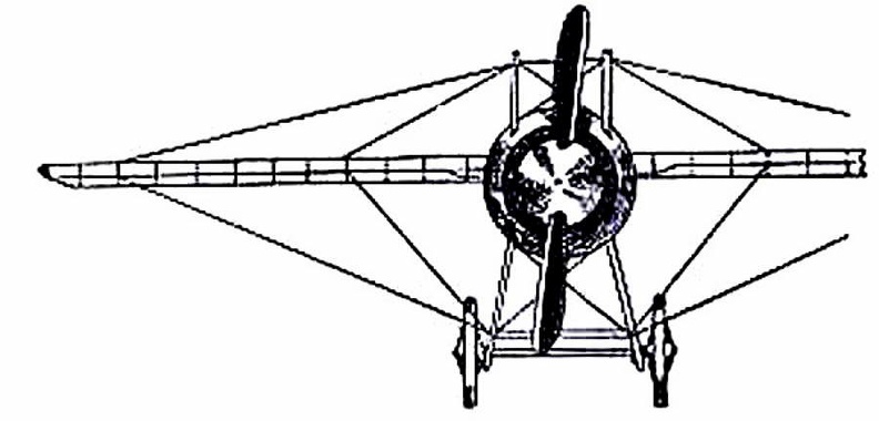
") Arrangement of iron plate, braces and scale of parlor size grand pianoforte
Arrangement of iron plate, braces and scale of parlor size grand pianoforte (793 visits)") Iron plate for upright pianoforte with Agraffes (Mehlin patents)
Iron plate for upright pianoforte with Agraffes (Mehlin patents) (799 visits) showing the “stream-line” effect which is gained by tapering the body, also the simplification o...") Racing Deperdussin Monoplane (front view)
Racing Deperdussin Monoplane (front view)
showing the “stream-line” effect which is gained by tapering the body, also the simplification of the landing chassis, and the use of a minimum of wires. photo id=7984] 1. Key.
2. Jack.
3. Jack-operating spring.
4. Cushion limiting rebound of jack.
5...") Cristofori’s action in its final form
Cristofori’s action in its final form
1. Key. 2. Jack. 3. Jack-operating spring. 4. Cushion limiting rebound of jack. 5. Under-hammer. 6. Hammer-butt. 7. Hinge of hammer-butt. 8. Hammer-shank. 9. Hammer head. 10. Check. 11. Damper-lifter. 12. Damper-head. 13. Action-beam. 14. Wrest-plank. 15. Tuning pins. 16. Bearing-bridge. 17. String. 1. Key.
2. Wippen.
3. Jack.
4. Escapement lever.
5. Hammer-shank.
6. Hammer-b...") The Erard grand action modified by Herz
The Erard grand action modified by Herz
1. Key. 2. Wippen. 3. Jack. 4. Escapement lever. 5. Hammer-shank. 6. Hammer-butt notch. 7. Hammer-head. 8. Jack regulating button. 9. Regulating button to limit rise of escapement lever. 10. Hammer-butt. 11. Check. 12. Molded tail of hammer-head to engage with check. 13. Capstan-screw connecting key and wippen. 14. Action-rails. 15. Damper-head. 16. Damper-operating device. 17. Device to limit travel of jack. 18. Regulating device for escapement lever. 19. Springs (2) for escapement lever and jack. 20. String. 21. Flange.") Map of Tank Operations, August–November, 1918
Map of Tank Operations, August–November, 1918 The Calabrian Bagpipe or Zampogna is a rudely carved instrument of the eighteenth century. It has fo...") Cornemuse, Calabrian Bagpipe, Musette
Cornemuse, Calabrian Bagpipe, Musette
The Calabrian Bagpipe or Zampogna is a rudely carved instrument of the eighteenth century. It has four drones attached to one stock, hanging downwards from the end of the bag: two of them are furnished with finger-holes. The reeds are double like those of the oboe and bassoon. The bag is large; it is inflated by the mouth and pressed by the left arm against the chest of the performer. The Zampogna is chiefly used as an accompaniment to a small reed melody pipe called by the same name, and played by another performer. The quality of the tone produced is not unpleasing. It has five holes only, and consequently the seventh of the scale is absent, but this can be easily got by octaving the open note of the pipe and covering part of the lower opening of the chanter with the little finger. The Musette, Zampogna, and Cornemuse here shown are from specimens belonging to Messrs. J. & R. Glen, Edinburgh., Streicher Viennese escapement (1794) (849 visits) 1. Key.
2. Jack.
3. Jack-operating spring.
4. Cushion limiting rebound of jack.
5...") Action by Andreas and Nanette (Stein), Streicher Viennese escapement (1794)
Action by Andreas and Nanette (Stein), Streicher Viennese escapement (1794)
1. Key. 2. Jack. 3. Jack-operating spring. 4. Cushion limiting rebound of jack. 5. Button and screw regulating escapement of hammer. 6. Hammer-butt and operating face. 7. Hammer-butt pivot. 8. Hammer-shank. 9. Hammer-head. 10. Check. 11. Damper-lifter. 12. Damper-head. 13. Action-rails. An experiment was made by Patrick Miller, a banker in Edinburgh, aided by Mr. Taylor, tutor in his f...") Miller’s twin boat on Loch Dalswinton, 1788
Miller’s twin boat on Loch Dalswinton, 1788
An experiment was made by Patrick Miller, a banker in Edinburgh, aided by Mr. Taylor, tutor in his family, and Alexander Symington, a practical engineer. Mr. Miller had a boat built and fitted with a small steam-engine, for his amusement, on Dalswinton Loch, Dumfriesshire. It was a twin-boat, the engine being placed on one side, the boiler on the other, and the paddle-wheel in the centre. It was launched in October, 1788, and attained a speed of five miles an hour. The engine, of one horse-power, is still to be seen in the Andersonian Museum, in Glasgow. Encouraged by his experiment, Mr. Miller bought one of the boats used on the Forth and Clyde Canal, and had a steam-engine constructed for it by the Carron Ironworks Company, under Symington’s superintendence. On December 26th, 1789, this steamboat towed a heavy load on the canal, at a speed of seven miles an hour; but, strange to say, the experiment was dropped as soon as it was tried.") Iron plate for upright pianoforte fitted with Capo D’astro bar
Iron plate for upright pianoforte fitted with Capo D’astro bar The origin of the cash register is rather nebulous, because twenty-five years ago several men were w...") Cash Register
Cash Register
The origin of the cash register is rather nebulous, because twenty-five years ago several men were working on the same idea. It first appeared as a practical machine in the offices of John and James Ritty, who owned stores and coalmines at Dayton, Ohio. James Ritty helped and largely paid for the first experiments. He needed a mechanical cashier for his own business, and says that, while on an ocean steamer en route to London the revolving machinery gave him the suggestion worked out, on his return to Dayton, in the first dial-machine. This gave way to the key-machine with its display tablet, or indicator, held up by a supporting bar moved back by knuckles on the vertical tablet rod. The cut shows the right side of this key register, the action of which is thus described by the National Cash Register Company. The key A, when pressed with the finger at its ordinary position—marked 1—went down to the point marked 2. Being a lever and pivoted to its centre, pressing down a key elevated its extreme point B. This pushed up the tablet-rod C, having on its upper part the knuckle D. This knuckle D, pushed up, took the position at E; that is, the knuckle pushed back the supporting-bar F, and was pushed past it and held above it. If the same operation were performed on another key, the knuckle on its vertical rod, going up, would again push the supporting bar back, which would release the first knuckled rod, and leave the last one in its place. This knuckled rod had on its upper end the display tablet, or indicator G (872 visits) 1. Key.
2. Jack.
3. Jack operating spring.
4. Rail and cushion limiting travel of jac...") English direct lever grand action, developed by Broadwood from Backers (1884)
English direct lever grand action, developed by Broadwood from Backers (1884)
1. Key. 2. Jack. 3. Jack operating spring. 4. Rail and cushion limiting travel of jack. 5. Button and screw regulating escapement of hammer. 6. Hammer-butt with operating notch. 7. Hammer-butt flange. 8. Hammer-shank. 9. Hammer-head. 10. Check. 13. Action-rails. The extreme length of the Lamont Harp is 38 inches, and the extreme width 18½ inches. The sound che...") Lamont Harp
Lamont Harp
The extreme length of the Lamont Harp is 38 inches, and the extreme width 18½ inches. The sound chest, as with other ancient harps, is hollowed out of one piece of wood, but the back has been in this instrument renewed, although probably a long time ago. The sound chest is 30 inches long, 4 inches in breadth at the top, and 17 at the bottom. The comb projects 15½ inches. The broken parts of the bow are held together by iron clamps.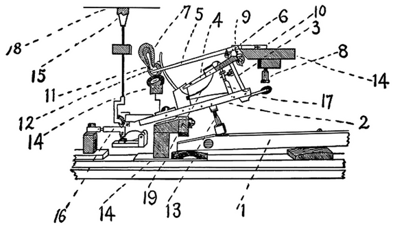 Double repetition action of Sebastian Erard as used by S. & P. Erard, Paris
1. Key. 2. Wippen. 3. Jack. 4. Escapement lever. 5. Hammer-shank. 6. Roller. 7. Hammer-head. 8. Jack regulating button. 9. Regulating button to limit rise of escapement lever. 10. Hammer-butt. 11. Check. 12. Felt cushion to engage with check. 13. Sticker connecting key and wippen. 14. Action-rails. 15. Damper-head. 16. Damper operating device. 17. Device to limit travel of jack. 18. String. 19. Spring (v-shaped) for escapement lever and jack.") A ‘Schneider’ armoured car with quick-firing gun
A ‘Schneider’ armoured car with quick-firing gun Fifty years later witnessed the full development of Mr. Bell’s ideal in the Columba, then as now t...") “Columba,” famous Clyde river steamer, 1875
“Columba,” famous Clyde river steamer, 1875
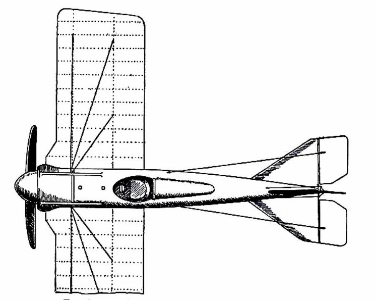
Fifty years later witnessed the full development of Mr. Bell’s ideal in the Columba, then as now the largest river steamer ever seen on the Clyde, and the swiftest. The Columba is built of steel, is 316 feet long and 50 feet wide. She has two oscillating engines of 220 horse-power, and attains a speed of twenty-two miles an hour. Her route is from Glasgow to Ardrishaig and back, daily in summer, when she carries from 2,000 to 3,000 persons through some of the finest scenery in Scotland. She is provided with steam machinery for steering and warping her into the piers, and with other modern appliances that make her as handy as a steam yacht. She resembles a little floating town, with shops and post-office where you can procure money orders and despatch telegrams And what is the Columba after all but an enlarged and perfected reproduction of Bell’s Comet! (903 visits)") Racing Deperdussin Monoplane (top view)
Racing Deperdussin Monoplane (top view)") An Italian design for a motor battery of quick-firing guns
An Italian design for a motor battery of quick-firing guns Beautiful horns of hammered and embossed bronze belonging to the Corporations of Canterbury and Dove...") Burgmote Horns
Burgmote Horns
Beautiful horns of hammered and embossed bronze belonging to the Corporations of Canterbury and Dover. The right-hand one is from Dover, where it was formerly used for the calling together of the Corporation at the order of the mayor. The minutes of the town proceedings were constantly headed "At a common Horn blowing" (comyne Horne Blowying). This practice continued until the year 1670, and is not yet entirely done away with, as it is still blown on the occasion of certain Municipal ceremonies. The motto on this horn is:— JOHANNES DE · ALLEMAINE · ME · FECIT · preceded by the talismanic letters A·G·L·A, which stand for the Hebrew אַתָּה גִּבּוֹר לְעוֹלָם אֲדֹנָי and mean, "Thou art mighty for ever, O Lord!" The horn, which is 31¾ inches long, with a circumference at the larger end of 15½ inches, is of brass, and is deeply chased with a spiral scrollwork of foliage chiefly on a hatched ground. The inscription is on a band that starts four inches from the mouth and continues spirally. The maker's name is now nearly effaced, but the inscription shows that he was a German, and the date is assigned to the thirteenth century.