


« 2020
2022 »
January
February
March
April
May
June
July
August
September
October
November
December
All

 By 1903 the Wright Brothers were ready to build a powered man-carrying flying machine. Their experim...") Wright Brothers first powered airplane
Wright Brothers first powered airplane
By 1903 the Wright Brothers were ready to build a powered man-carrying flying machine. Their experiments had shown them just how much moving air was necessary to create lift in such a machine. To create the needed thrust, an engine having eight horsepower and weighing not over 200 pounds had to be fitted into the machine. Such an engine was not available, so the Wrights built one in their shop at Dayton, Ohio. They were ready to ship their airplane to Kitty Hawk, N. C., in the fall of 1903. After a year of exhaustive study and experiments with models in their wind tunnel, the Wright Brothe...") The Wright Brothers experimental glider
The Wright Brothers experimental glider
After a year of exhaustive study and experiments with models in their wind tunnel, the Wright Brothers were ready to experiment with a man-carrying glider. With the thoroughness that was typical of every move of the Wrights, the brothers asked the government to let them have information on meteorological conditions all over the country. By studying the weather charts they were able to find a locality where there was a continual flow of wind. This would be nature’s wind tunnel where they could test their glider day after day. Through their study of the charts they found that the wind conditions at Kitty Hawk, on the North Carolina coast, seemed to offer the best possibilities for their glider test. Orville and Wilbur Wright began their experiments with a small man-carrying glider at Kitty Hawk in 1900. From that time until 1903 they made hundreds of successful glider flights and kept accurate records of each flight. They recorded wind velocity, angle of flight, duration of flight, time of day, temperature, humidity, and sky conditions overhead with the typical Wright attention to detail. Each year the Wrights constructed new gliders which embodied principles they had discovered for themselves during their flights at Kitty Hawk. Each glider was larger and had longer and narrower wings than the one before. During the fall of 1902 the brothers recorded nearly a thousand flights in a glider with a wingspan of thirty-two feet. It had a front elevator and a vertical tail which helped to maintain lateral stability. after testing more than 200 wing designs and plane surfaces in their wind tunnel, the Wright Brother...") The Four forces of flight
The Four forces of flight
after testing more than 200 wing designs and plane surfaces in their wind tunnel, the Wright Brothers found out how to figure correctly the amount of curve, or camber, that was essential to weight-carrying wings. They discovered, too, that before man could be flown through the air, he must have his wings attached firmly to a body or platform which was firm and controllable. The Wrights in their earliest experiments had realized that to be practical their machine must be built not only to fly in a straight line, but also in order that it could be steered to the right or to the left. One day, Orville was twisting a cardboard box in his hand when Wilbur noticed it. Immediately he saw the solution to the problem of steering their airplane. The result was a design which changed the lift of either end of the wing by warping its surface. If one end of the wing was warped to give it more lift, the machine would lift on that side and fall off into a turn. Thus the problem of steering was solved by the Wrights They found that a slight curve or camber in the wing section would cause the moving air to travel fa...") Wright Brothers' Wind tunnel
Wright Brothers' Wind tunnel
They found that a slight curve or camber in the wing section would cause the moving air to travel farther over the top of the wing surface than along the under side. This made the air pressure greater under the wing, gave a suction effect above the wing, and caused it to rise, creating lift. They discovered that a wing section of the proper camber would counteract the weight of gravity. Thus, a wing must be so designed that, with a certain amount of air flowing around it, it would lift a certain weight. They also discovered that air flow against any surface attached to the wing would cause a resistance or drag. Hundreds of experiments in their wind tunnel with various types of wing shapes gave the Wrights a series of tables from which to design a wing that would create the lift for a designed weight. The Wright Brothers were not only inspired mechanics (as many people still believe today) but seriou...") Wright Brotherrs wind tunnel
Wright Brotherrs wind tunnel
The Wright Brothers were not only inspired mechanics (as many people still believe today) but serious scientists, working along the soundest lines. In their keen desire to know what air pressure on wings really was, they cleared a corner of their bicycle shop and built a small wind tunnel with spare lumber and an old electric fan. They built small wing sections of various shapes and experimented with them in their wind tunnel. The electric fan was used to create the moving air around the wing section. By attaching the wing sections to a supporting frame and connecting the frame with a pointer and dial, they were able to keep a record of the effect of moving air on each experimental wing section. Through their wind tunnel research the Wright Brothers discovered the four forces that control all heavier-than-air flight: lift, thrust, weight, and drag. Out in Dayton, Ohio, there were two small brothers, who dreamed, as countless other children before ...") Wright Brothers' Bicycle shop
Wright Brothers' Bicycle shop
Out in Dayton, Ohio, there were two small brothers, who dreamed, as countless other children before them had dreamed, of flying like birds through the air. Their dreams were heightened by a small toy given to them by their father, the pastor of a local church. This toy was to lead to an idea which had a profound effect on the world. You would probably call it a flying propeller. It consisted of a wooden propeller which slipped over a notched stick. By placing a finger against the propeller and rapidly pushing it up the notched stick, the propeller was made to whirl up off the end of the stick and fly into the air. The brothers, young as they were, never quite forgot this little toy as they continued to dream of flying like birds through the air. Though the brothers continued to dream of flying, they were not the kind of lads who spent all their time in dreaming. They made kites which flew a little better and a little higher than those made by the other boys in the neighborhood. They built a press to print their own little newspaper, and they dabbled in woodcuts. To carve out porch posts for their father’s home they built an eight-foot wood-turning lathe. Indeed, they were the sort of boys who caused the neighbors to say, “What will they think of next?” The brothers knew that if they ever wanted to see their dreams come true they must earn their own capital. In the early nineties America was in the midst of the bicycle craze. Everyone who could possibly afford to do so owned a bicycle of some sort and belonged to a cycle club. Being mechanically minded, the brothers did the logical thing. They set themselves up in a small bicycle shop in Dayton, next door to their home. The bicycle shop in Dayton prospered, for the brothers were careful and expert mechanics, and cyclists in need of repairs made their way to the Wright Brothers’ shop. Langley built his plane without much difficulty, but could not find anyone to make an engine large e...") The Aerodrome
The Aerodrome
Langley built his plane without much difficulty, but could not find anyone to make an engine large enough for it. Finally, Charles Manley, an expert engineer, asked for permission to build the engine. Manley’s engine was a five-cylinder, radial gasoline engine that developed 51 horsepower and was far ahead of its time. It was years before American radial engines were used successfully in airplanes. Professor Langley called his machine the Aerodrome, and by October, 1903, the plane was ready for its test flight, with Manley to guide it. The Aerodrome was to be launched from a catapulting platform built on the roof of a houseboat. The houseboat was anchored on the Potomac River near Washington. As it left the platform the machine crashed into the river, and the trial was a dismal failure. The newspapers and the public ridiculed Langley, but he and Manley, who was unhurt in the crash, repaired the machine for another trial. This test took place on December 8, 1903, and again the Aerodrome crashed into the river. Manley once more escaped injury, but Langley and the government were abused by the public for wasting money. Langley was out of money himself, the government could not furnish funds for further trials, so the experiments were ended. The professor, discouraged and brokenhearted, gave up. Octave Chanute, born in France and reared in America, was one of the first men to make a scientific ...") Octave Chanute experimenting with his gliders on the Michigan sand dunes
Octave Chanute experimenting with his gliders on the Michigan sand dunes
Octave Chanute, born in France and reared in America, was one of the first men to make a scientific approach to the problem of flying machines. A thorough scientist, he had followed the progress of all flight experiments the world over. He built gliders with one, two, and even five pairs of wings and tested all of them on the sand dunes of Lake Michigan. His most successful glides were made with a biplane glider. In 1894, he published a book called Progress of Flying Machines, which covered all the efforts of men like himself who had experimented with man-carrying gliders and flying machines. Leonardo da Vinci, the great Italian artist and scientist, who lived in the fifteenth century, spent...") Leonardo da Vinci's Glider and Parachute Idea
Leonardo da Vinci's Glider and Parachute Idea
Leonardo da Vinci, the great Italian artist and scientist, who lived in the fifteenth century, spent years experimenting with the idea of flying. He made a number of sketches of wings to be fitted to the arms and legs of man. His plan for a parachute was soundly worked out and his idea that the wings of a flying machine should be patterned after the wings of the bat found expression in the doped fabric covering of our early airplanes. In 1678, Besnier, a French locksmith, constructed a curious flying machine consisting of two wooden ...") Besnier and his wings
Besnier and his wings
In 1678, Besnier, a French locksmith, constructed a curious flying machine consisting of two wooden bars which rested on his shoulders. At the ends of the bars he attached muslin wings, arranged to open on the down stroke and close on the up stroke. The wings were operated by moving the arms and legs. Although Besnier failed to realize that no man had sufficient muscular strength to fly as the bird flies, he did sense part of the truth—that gliding with the air currents was possible. During his experiments he is said to have jumped from a window sill, glided over the roof of a near-by cottage, and landed on a barge in the river. Historians have unearthed stories in cuneiform writing of man’s attempts to fly. Some of these ins...") The flight of Etana
The flight of Etana
Historians have unearthed stories in cuneiform writing of man’s attempts to fly. Some of these inscriptions date back more than five thousand years, to 3500 B.C. Perhaps the most famous of these stories is the ancient Babylonian tale of the shepherd boy, Etana, who rode on the back of an eagle. The story of Dædalus and Icarus also tells us that man believed flying was somehow possible. Dædal...") Daedalus and Icarus
Daedalus and Icarus
The story of Dædalus and Icarus also tells us that man believed flying was somehow possible. Dædalus was a very clever man who lived with his son Icarus on the Island of Crete. The king of this island requested Dædalus to build a labyrinth or maze for him. Dædalus constructed the labyrinth so cleverly that only the king, who had the clue to the winding passages, could find his way out. One day the king became very angry at Dædalus and threw both him and his son Icarus into the labyrinth, intending that they should perish. Dædalus, who had been dreaming of flying, fashioned wings from wax and feathers, with which he and Icarus could fly to freedom. He cautioned Icarus that he must not fly too high or the sun would melt the wax in his wings. Icarus, impatient to escape, scarcely listened. Like birds the two flew into the air, quickly leaving the walls of the labyrinth. Dædalus, flying low, safely crossed the sea and reached Sicily. Icarus, unfortunately, failed to heed his father’s warning. Flying was so much fun that he rose higher and higher. Suddenly feathers began to drop one by one. Too late Icarus realized that the sun had melted the wax in his wings. Down, down he fell into the sea.") Banked turn on a biplane
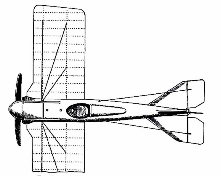
Banked turn on a biplane Put together scientifically and from sections of wood specially tested, a remarkable strength may be...") Testing the girder-built body of an aircraft
Testing the girder-built body of an aircraft
Put together scientifically and from sections of wood specially tested, a remarkable strength may be obtained by such a method of building. The figure shows how a girder aircraft body, supported by trestles only at its ends, may support from its centre, without yielding, a tray containing a number of heavy weights") Construction of a Monoplane wing
Construction of a Monoplane wing The driver of a modern-type aeroplane, sitting snugly within its hull, has a wheel and instrument-bo...") The Control of a Biplane
The Control of a Biplane
The driver of a modern-type aeroplane, sitting snugly within its hull, has a wheel and instrument-board before him, as sketched. As he flies across country he has many things to think of. Holding the control-wheel in both hands, his feet resting upon the rudder-bar, his eyes rove constantly among the instruments [Pg 163]on the dashboard before him. He glances at the compass often, for it is by this that he steers; and when the air is clear, and the earth below plainly seen, he will every now and then glance over the side of the hull, so as to be on the look-out for a landmark that may tell him he is on his course. A. Pilot’s seat B. Hand-wheel (pushed forward or backward operates elevator; twisted sideways works ailerons) C. Foot-bar actuating rudder D. Compass E. Dial showing number of revolutions per minute that engine is making F. Gauge showing pressure in petrol tank G. Speed indicator H. Dial showing altitude I. Clock J. Switch for cutting off ignition. (803 visits) In the development of speed, some remarkable craft are built. Each year there is an international ai...") Racing Deperdussin Monoplane (side view)
Racing Deperdussin Monoplane (side view)
In the development of speed, some remarkable craft are built. Each year there is an international air race for the possession of the Gordon-Bennett trophy, and to win this designers build special craft. In tiny monoplanes, engines of high power are installed; and the sustaining wings are so reduced, to give a maximum speed, that the machines appear more like projectiles than flying craft. A purely racing-type monoplane is seen in figure.. It represents a Deperdussin, which, with an engine of 160 horse-power, reached a speed of 130 miles an hour. How small this machine was, in relation to its engine-power, will be realised from the fact that the sustaining surface of its wings amounted to only 104 square feet—far less lifting area, in fact, than Lilienthal used in his gliders. Wires and struts are reduced to a minimum; the body is tapered and smoothed. Such a machine, although it carries speed to an extreme, and is in reality a “freak,” teaches useful lessons. But though it provides data for the construction of high-speed scouts, a monoplane of this type would be useless for cross-country flying; and for the reason that it cannot be manœuvred, prior to an ascent, upon anything save the smoothest of ground. Its wings being so small, to ensure a maximum of speed, the machine will not rise until it has run forward a long distance across the ground; and during this run it attains a speed of nearly 90 miles an hour. At such a pace, unless the ground below its wheels was level, it would leap, swerve, and probably overturn. When alighting from a flight, also, again owing to the smallness of its wings, the craft has to plane down so fast that its pilot could not land safely unless he had below him a surface that was absolutely smooth. A. Propeller B. Shield to lessen wind resistance C. Sloping shield which encloses engine (also to minimise wind-pressure). Air passes between the shields B and C to cool the motor. D. Pilot’s seat E. Padded projection against which, when at high speed, the pilot rests his head F. Sustaining-plane Very slightly cambered G. Rudder H. Elevating-plane I. Landing wheels.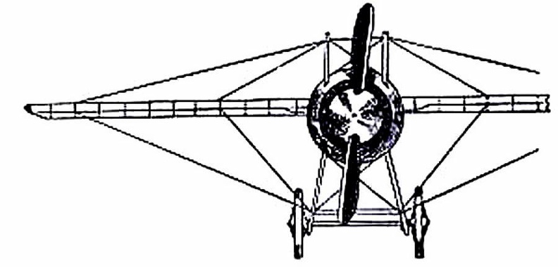
 (811 visits) showing the “stream-line” effect which is gained by tapering the body, also the simplification o...") Racing Deperdussin Monoplane (front view)
Racing Deperdussin Monoplane (front view)
showing the “stream-line” effect which is gained by tapering the body, also the simplification of the landing chassis, and the use of a minimum of wires. photo id=7984] (909 visits)") Racing Deperdussin Monoplane (top view)
Racing Deperdussin Monoplane (top view) An Old-fashioned Train of Cars") An Old-fashioned Train of Cars
An Old-fashioned Train of Cars
An Old-fashioned Train of Cars During the Crimean War, Boydell’s traction machine was used to haul open trucks on the road and ac...") The 'Hercules' Traction Engine, as used during the Crimean War
The 'Hercules' Traction Engine, as used during the Crimean War
During the Crimean War, Boydell’s traction machine was used to haul open trucks on the road and across country. Its engine, the “Hercules,” was fitted with a curious arrangement, which, by means of rails attached in six sections to the wheels, enabled it to lay down and take up its own track as it went along.") A 'Fischer' Combination Omnibus
A 'Fischer' Combination Omnibus But a means of adapting a mono-rail to every condition had some time before been thought out. In 188...") Plan of a Behr Mono-Railway Car
Plan of a Behr Mono-Railway Car
But a means of adapting a mono-rail to every condition had some time before been thought out. In 1883-4 Charles Lartigue, the eminent French engineer, developing the principle conceived by the great Telford, constructed some small lines in Tunis and Algeria for carrying esparto grass. The cars were drawn by animals in a special form of mono-rail, the model upon which Mr. F. B. Behr, ASS. INST. C.E.—who modestly disclaims all originality in the matter—has worked for years, greatly improving in practical details the original design, and constructing for the first time mono-rail trains that have been successful in the carriage of both goods and passengers by steam and electricity. Electrical Power House (the largest in the Old World), Lot’s Road, Chelsea, to supply the Metropol...") Electrical Power House
Electrical Power House
Electrical Power House (the largest in the Old World), Lot’s Road, Chelsea, to supply the Metropolitan District and other Railways with Current") A Krupp motor gun-carrying lorry
A Krupp motor gun-carrying lorry") A ‘Schneider’ armoured car with quick-firing gun
A ‘Schneider’ armoured car with quick-firing gun") A ‘Charron’ armoured car with machine gun
A ‘Charron’ armoured car with machine gun") An Italian design for a motor battery of quick-firing guns
An Italian design for a motor battery of quick-firing guns") A type of extemporised motor ambulance favoured by the French and Belgians
A type of extemporised motor ambulance favoured by the French and Belgians") Travelling Post, 1825-35
Travelling Post, 1825-35") Royal Mail Coach
Royal Mail Coach The coaches that travelled between London and distant towns were similar in construction to the hack...") The Machine, 1640-1700
The Machine, 1640-1700
The coaches that travelled between London and distant towns were similar in construction to the hackney coach, which plied for hire in the streets, but were built on a larger scale. They carried eight passengers inside, and behind, over the axle, was a great basket for baggage and outside passengers, who made themselves as comfortable as they might in the straw supplied. The “insides” were protected from rain and cold by leather curtains; neither passengers nor baggage were carried on the roof; and the coachman sat on a bar fixed between the two standard posts from which the body was hung in front, his feet being supported by a footboard on the perch. Mr. Thrupp states that in 1662 there were only six stage coaches in existence; which assertion does not agree with that of Chamberlayne, quoted on a previous page; the seventeenth century writer tells us that in his time—1649—stage coaches ran “from London to the principle towns in the country.” It seems, however, certain that the year 1662 saw a great increase in the number of “short stages”—that is to say, coaches running between London and towns twenty, thirty, forty miles distant. Bourn’s reference to the “narrow-wheel waggon” touches a matter which formed the subject of ho...") Mr. Daniel Bourn’s Roller Wheel Waggon -1763
Mr. Daniel Bourn’s Roller Wheel Waggon -1763
Bourn’s reference to the “narrow-wheel waggon” touches a matter which formed the subject of hot debate for generations. It was urged that the narrow wheels of waggons were largely the means of cutting up the roads, and no doubt these did contribute to the general condition of rut and ridge that characterised them. This view was adopted by Parliament, and to encourage the use of wide wheels a system of turnpike tolls was adopted which treated the wide tire far more leniently than the narrow; anything under 9 inches in width being considered narrow. Bourn was a warm advocate for wide wheels, and the book from which the above passage is taken describes an improved waggon invented by himself; the drawing is[80] from the inventor’s work. The wheels of this vehicle resemble small garden rollers; they are 2 feet high and 16 inches wide. Each is attached independently to the body of the waggon and the fore wheels being placed side by side in the centre, while the hind wheels are set wide apart, the waggon is practically designed to fulfil the functions of a road-roller. It does not appear that Bourn’s invention obtained any general acceptance, which is perhaps not very surprising. Queen Elizabeth travelled in a coach, either the one built by Walter Rippon or that brought by Boone...") Queen Elizabeth’s Travelling Coach
Queen Elizabeth’s Travelling Coach
Queen Elizabeth travelled in a coach, either the one built by Walter Rippon or that brought by Boonen (who, by the way, was appointed her coachman), on some of her royal progresses through the kingdom. When she visited Warwick in 1572, at the request of the High Bailiff she “caused every part and side of the coach to be opened that all her subjects present might behold her, which most gladly they desired.” The vehicle which could thus be opened on “every part and side” is depicted incidentally in a work executed by Hoefnagel in 1582, which Markland believed to be probably the first engraved representation of an English coach. As will be seen from the reproduction here given, the body carried a roof or canopy on pillars, and the intervening spaces could be closed by means of curtains. (656 visits)") London Hackney Cab (Boulnois’ Patent)
London Hackney Cab (Boulnois’ Patent)") King George IV. in His Pony Phaeton
King George IV. in His Pony Phaeton, 1750 (620 visits)") Travelling Posting Carriage (2), 1750
Travelling Posting Carriage (2), 1750, 1750 (667 visits)") Travelling Posting Carriage (1), 1750
Travelling Posting Carriage (1), 1750 From Engraving, A.D. 1750.") Going to Bury Fair
Going to Bury Fair
From Engraving, A.D. 1750. Carriage used about 1300-1350 in Flanders.
Carriages were in use on the continent long before they ...") Flight of Princess Ermengarde
Flight of Princess Ermengarde
Carriage used about 1300-1350 in Flanders. Carriages were in use on the continent long before they were employed in England. In 1294, Philip the Fair of France issued an edict whose aim was the suppression of luxury; under this ordinance the wives of citizens were forbidden to use carriages, and the prohibition appears to have been rigorously enforced. They were used in Flanders during the first half of the fourteenth century; an ancient Flemish chronicle in the British Museum (Royal MSS. 16,[9] F. III.) contains a picture of the flight of Ermengarde, wife of Salvard, Lord of Rouissillon. Showing near-side “Boot.”
Coaches with \"Boots\"
From Coach and Sedan, we obtain a quaint bu...") Coach of Queen Elizabeth’s Ladies
Coach of Queen Elizabeth’s Ladies
Showing near-side “Boot.” Coaches with "Boots" From Coach and Sedan, we obtain a quaint but fairly graphic description of the coach of this period:— “The coach was a thick, burly, square-set fellow in a doublet of black leather, brasse button’d down the breast, back, sleeves and wings, with monstrous wide boots, fringed at the top with a net fringe, and a round breech (after the old fashion) gilded, and on his back an atchievement of sundry coats [of arms], in their proper colours.” The “boots” were projections at the sides of the body between the front and back wheels, as shown in the drawing of the coach occupied by Queen Elizabeth’s ladies; and there is much evidence to support the opinion that these boots were not covered. Horse litters, carried between two horses, one in front and one behind, were used in early times by ...") Horse Litter
Horse Litter
Horse litters, carried between two horses, one in front and one behind, were used in early times by ladies of `rank`, by sick persons, and also on occasion to carry the dead. Similar vehicles of a lighter description, carried by men, were also in use. William of Malmesbury states that the body of William Rufus was brought from the spot where he was killed in the New Forest in a horse-litter (a.d. 1100). When King John fell ill at Swineshead Abbey, in 1216, he was carried in a horse-litter to Newark, where he died. For a man who was in good health to travel in such a conveyance was considered unbecoming and effeminate. In recording the death, in 1254, of Earl Ferrers, from injuries received in an accident to his conveyance, Matthew Paris deems it necessary to explain that the Earl suffered from gout, which compelled him to use a litter when moving from place to place. The accident was caused by the carelessness of the driver of the horses, who upset the conveyance while crossing a bridge. The illustration is copied from a drawing which occurs in a manuscript in the British Museum (Harl. 5256). Supposed to have been in use in England about
A.D.. 1100-1200.
Strutt states that the chariot ...") Hammock Waggon
Hammock Waggon
Supposed to have been in use in England about A.D.. 1100-1200. Strutt states that the chariot of the Anglo-Saxons was used by distinguished persons for travel. If the illustrations from which he describes them give a fair idea of their proportions and general construction, they must have been singularly uncomfortable conveyances. The drawing is taken from an illuminated manuscript of the Book of Genesis in the Cotton Library (Claud. B. iv.), which Strutt refers to the ninth century, but which a later authority considers a production of the earlier part of the eleventh. The original drawing shows a figure in the hammock waggon, which figure represents Joseph on his way to meet Jacob on the latter’s arrival in Egypt; this figure has been erased in order to give a clear view of the conveyance, which no doubt correctly represents a travelling carriage of the artist’s own time, viz., a.d. 1100-1200. Excessive number of Coaches in London.
The preamble of a patent granted Sir Saunders Duncombe in ...") Hackney Coaches in London, 1637
Hackney Coaches in London, 1637
Excessive number of Coaches in London. The preamble of a patent granted Sir Saunders Duncombe in 1634 to let Sedan chairs refers to the fact that the streets of London and Westminster “are of late time so much encumbered and pestered with the unnecessary multitude of coaches therein used”; and in 1635 Charles I. issued a proclamation on the subject. This document states that the “general and promiscuous use” of hackney coaches in great numbers causes “disturbance” to the King and Queen personally, to the nobility and others of place and degree; “pesters” the streets, breaks up the pavements and cause increase in the prices of forage. For which reasons the use of hackney coaches in London and Westminster and the suburbs is forbidden altogether, unless the passenger is making a journey of at least three miles. Within the city limits only private coaches were allowed to ply, and the owner of a coach was required to keep four good horses or geldings for the king’s service.") Locomotive of To-day
Locomotive of To-day A \"No. 2 flying boat,\" just built by Mr. Curtiss, and successfully tested on Lake Keuka, Hammondspor...") Diagram of the Curtiss Flying Boat no. 2
Diagram of the Curtiss Flying Boat no. 2
A "No. 2 flying boat," just built by Mr. Curtiss, and successfully tested on Lake Keuka, Hammondsport, in July, 1912, is the "last word" in aviation so far. An illustration in this book, made from photographs taken in mid-July, 1912, shows fully the bullet-shape of the "flying fish." It is a real boat, built with a fish-shaped body containing two comfortable seats for the pilot and passenger or observer, either of whom can operate the machine by a system of dual control, making it also available for teaching the art of flying. All the controls are fastened to the rear of the boat's hull, which makes them very rigid and strong, while the boat itself, made in stream-line form, offers the least possible resistance to the air, even less than that offered by the landing gear upon a standard land machine. Above the boat are mounted the wings and aeroplane surface. In the centre of this standard biplane construction is situated the eighty horse-power motor with its propeller in the rear, thus returning to the original practice, as in the standard Curtiss machines, of having a single propeller attached direct to the motor, thus doing away with all chains and transmission gearing which might give trouble, and differing from the earlier model flying boat built in San Diego, California, last winter (1911-12), which was equipped with "tractor" propellors propellers in front driven by chains. The new flying boat is twenty-six feet long and three feet wide. The planes are five and a half feet deep and thirty feet wide. It runs on the water at a speed of fifty miles an hour, and is driven by an eighty horse-power Curtiss motor. At a greater speed than this it cannot be kept on the water, but rises in the air and flies at from fifty to sixty miles per hour. Following the success of the \"White Wing\" we started in to build another machine, embodying all that...") Scientific American Trophy
Scientific American Trophy
Following the success of the "White Wing" we started in to build another machine, embodying all that we had learned from our experience with the two previous ones. Following our custom of giving each machine a name to distinguish it from the preceding one, we called this third aeroplane the "June Bug." The name was aptly chosen, for it was a success from the very beginning. Indeed, it flew so well that we soon decided it was good enough to win the trophy which had been offered by The Scientific American for the first public flight of one kilometer, or five-eights of a mile, straightaway. This trophy, by the way, was the first to be offered in this country for an aeroplane flight, and the conditions specified that it should become the property of the person winning it three years in succession. The "June Bug" was given a thorough try-out before we made arrangements to fly for the trophy, and we were confident it would fulfill the requirements. 1. Cylinder; 2. Engine Bed; 3. Fuel Tank: 4. Oil Pan; 5. Radiator; 6. Propeller; 7. Crank Case; 8. C...") Diagram of Curtiss motor, side and front views
Diagram of Curtiss motor, side and front views
1. Cylinder; 2. Engine Bed; 3. Fuel Tank: 4. Oil Pan; 5. Radiator; 6. Propeller; 7. Crank Case; 8. Carbureter; 9. Gasoline Pipe; 10. Air Intake; 11. Auxiliary Air-pipe; 12. Drain Cock; 13. Water Cooling System; 14. Gas Intake Pipe; 15. Rocker Arm; 16. Spring on Intake Valve; 17. Spring on Exhaust Valve; 18. Exhaust Port; 19. Rocker Arm Post; 20. Push Rod. 1. Motor; 2. Radiator; 3. Fuel Tank; 4. Upper Main Plane; 5. Lower Main Plane; 6. Aileron; 7. Vertic...") Diagram of Curtiss Aeroplane, side view
Diagram of Curtiss Aeroplane, side view
1. Motor; 2. Radiator; 3. Fuel Tank; 4. Upper Main Plane; 5. Lower Main Plane; 6. Aileron; 7. Vertical Rudder; 8. Tail Surface; 9. Horizontal Rudder, or Rear Elevator; 10. Front Elevator; 11. Vertical Fin; 12. Steering Wheel; 13. Propeller; 14. Foot Throttle Lever; 15. Hand Throttle Lever; 16. Foot Brake. Gearless, 75 H.P. Gearless Transmission Co., Rochester, N. Y.
PRICE: $3,750
BODY: Side entr...") Gearless, 75 H.P
Gearless, 75 H.P
Gearless, 75 H.P. Gearless Transmission Co., Rochester, N. Y. PRICE: $3,750 BODY: Side entrance tonneau SEATS: 7 persons WEIGHT: 3,000 pounds WHEEL-BASE: 128 inches TREAD: 56 inches TIRES, FRONT: 36 × 4 inches TIRES, REAR: 36 × 4½ inches STEERING: Worm and nut BRAKES: On transmission and 2 on each rear hub SPRINGS: Semi-elliptical FRAME: Pressed steel BORE: 413/16 in.; STROKE: 5⅝ in. CYLINDERS: 6 vertical in front VALVE ARRANGEMENT: Inlet and exhaust in side ports MOTOR SUSPENSION: From sub-frame COOLING: Water IGNITION: Jump spark, 2 sets of plugs CURRENT SUPPLY: Storage battery and magneto CARBURETER: Float-feed LUBRICATION: Pump driven by gears MOTOR-CONTROL: Spark and throttle CLUTCH: Expanding ring CHANGE GEAR: Gearless 1907 model, direct drive SPEEDS: 2 forward and reverse CHANGE-GEAR CONTROL: Foot pedal for forward speeds; side lever for back up DRIVE: Shaft Hercules, Model 101. James Macnaughtan Co., Buffalo, N. Y.
PRICE: $2,000
BODY: Closed deliv...") Hercules, Model 101
Hercules, Model 101
Hercules, Model 101. James Macnaughtan Co., Buffalo, N. Y. PRICE: $2,000 BODY: Closed delivery wagon CAPACITY: 1,000 pounds WEIGHT: 2,700 pounds TIRES, FRONT: 34 × 2 inches TIRES, REAR: 36 × 2 inches STEERING: Horizontal side lever BRAKES: Internal expanding hub SPRINGS: Front, half platform; rear, full elliptical MOTORS: Single equipment MOTOR SUSPENSION: From body MOTOR-CONTROL: Westinghouse CHANGE SPEEDS: 4 forward and reverse DRIVE: Double chain Frontenac, Model C, 40 H.P. Abendroth & Root Mfg. Co., Newburgh, N. Y.
PRICE: $3,500
BODY: ...") Frontenac, Model C, 40 H.P
Frontenac, Model C, 40 H.P
Frontenac, Model C, 40 H.P. Abendroth & Root Mfg. Co., Newburgh, N. Y. PRICE: $3,500 BODY: Side entrance tonneau SEATS: 5 to 7 persons WEIGHT: 2,800 pounds WHEEL-BASE: 123 inches TREAD: 56 inches TIRES, FRONT: 34 × 4 inches TIRES, REAR: 34 × 4½ inches STEERING: Bevel gear connecting to worm and nut BRAKES: Internal and external on rear wheels BORE: 4¾ in.; STROKE: 5 in. SPRINGS: Semi-elliptical FRAME: Pressed steel CYLINDERS: 4, vertical in pairs VALVE ARRANGEMENT: On same side MOTOR SUSPENSION: From sub-frame COOLING: Water, fin tube radiator IGNITION: Jump spark CURRENT SUPPLY: Storage battery and magneto CARBURETER: Automatic LUBRICATION: Splash MOTOR-CONTROL: Spark and throttle CHANGE GEAR: Sliding type SPEEDS: 3 forward and reverse CHANGE-GEAR CONTROL: Selective system DRIVE: Shaft Gearless, 50 H.P. Gearless Transmission Co., Rochester, N. Y.
PRICE: $3,000
BODY: Side entr...") Gearless, 50 H.P
Gearless, 50 H.P
Gearless, 50 H.P. Gearless Transmission Co., Rochester, N. Y. PRICE: $3,000 BODY: Side entrance tonneau SEATS: 5 persons WEIGHT: 2,600 pounds WHEEL-BASE: 124 inches TREAD: 56 inches TIRES, FRONT: 36 × 4 inches TIRES, REAR: 36 × 4 inches STEERING: Worm and nut BRAKES: On transmission and two on each rear hub SPRINGS: Semi-elliptical FRAME: Pressed steel BORE: 4⅝ in.; STROKE: 5 in. CYLINDERS: 4, vertical in front; two cycle MOTOR SUSPENSION: From sub-frame COOLING: Air jackets. Blower; copper fins cast on cylinders IGNITION: Jump spark CURRENT SUPPLY: Storage battery and dry cells CARBURETER: Float-feed LUBRICATION: Mechanical force feed oiler MOTOR-CONTROL: Spark and throttle CLUTCH: Expanding ring CHANGE GEAR: Gearless 1907 model, direct drive SPEEDS: 2 forward and reverse CHANGE-GEAR CONTROL: Foot pedal for forward speeds; ride lever for reverse DRIVE: Shaft Gearless, 60 H.P. Gearless Transmission Co., Rochester, N. Y.
PRICE: $3,250
BODY: Side entr...") Gearless, 60 H.P
Gearless, 60 H.P
Gearless, 60 H.P. Gearless Transmission Co., Rochester, N. Y. PRICE: $3,250 BODY: Side entrance tonneau SEATS: 5 persons WEIGHT: 2,800 pounds WHEEL-BASE: 124 inches TREAD: 56 inches TIRES, FRONT: 36 × 4 inches TIRES, REAR: 36 × 4 inches STEERING: Worm and nut BRAKES: On transmission and rear hubs SPRINGS: Semi-elliptical FRAME: Pressed steel BORE: 5 in.; STROKE: 5 in. CYLINDERS: 4 vertical in front, 2 cycle MOTOR SUSPENSION: From sub-frame COOLING: Water IGNITION: Double jump spark CURRENT SUPPLY: Magneto and battery CARBURETER: Float-feed LUBRICATION: Mechanical force feed MOTOR-CONTROL: Spark and throttle CLUTCH: Expanding ring CHANGE GEAR: Gearless direct drive SPEEDS: 2 forward and reverse CHANGE-GEAR CONTROL: Side lever and foot pedal DRIVE: Shaft Covert Commercial Car, 12 H.P. Covert Motor Vehicle Co., Lockport, N. Y.
PRICE: $1,000
BODY...") Covert Commercial Car, 12 H.P
Covert Commercial Car, 12 H.P
Covert Commercial Car, 12 H.P. Covert Motor Vehicle Co., Lockport, N. Y. PRICE: $1,000 BODY: Express (screen sides) CAPACITY: 1,000 pounds WEIGHT: 1,500 pounds WHEEL-BASE: 84 inches TREAD: 56 inches TIRES, FRONT: 32 × 2 inches TIRES, REAR: 32 × 2 inches SPRINGS: Full elliptic CYLINDERS: Double opposed MOTOR SUSPENSION: From side members of frame, under seat COOLING: Water; cellular radiator IGNITION: Jump spark CURRENT SUPPLY: Batteries CHANGE GEAR: Sliding type CHANGE-GEAR CONTROL: Side lever DRIVE: Shaft and bevel gears Frontenac Runabout, Model D, 40–45 H.P. Abendroth and Root M'f'g. Co., Newburgh, N. Y.
PRI...") Frontenac Runabout, Model D, 40–45 H.P
Frontenac Runabout, Model D, 40–45 H.P
Frontenac Runabout, Model D, 40–45 H.P. Abendroth and Root M'f'g. Co., Newburgh, N. Y. PRICE: $3,500 BODY: Runabout SEATS: 3 persons WEIGHT: 2,500 pounds WHEEL-BASE: 123 inches TREAD: 56 inches TIRES, FRONT: 36 × 3½ in. TIRES, REAR: 36 × 4½ in. STEERING: Bevel gear and shaft connecting to worm and nut BRAKES: External and internal on rear wheels SPRINGS: Semi-elliptical FRAME: Pressed steel BORE: 4¾ in.; STROKE: 5 in. CYLINDERS: 4 vertical, in pairs VALVE ARRANGEMENT: On one side MOTOR SUSPENSION: Sub-frame COOLING: Water; fin tube radiator IGNITION: Jump spark (double) CURRENT SUPPLY: Magneto and battery CARBURETER: Automatic float-feed LUBRICATION: Splash MOTOR-CONTROL: Spark and throttle CHANGE GEAR: Sliding type SPEEDS: 3 forward and reverse CHANGE-GEAR CONTROL: Selective system DRIVE: Shaft Chicago Coal or Gravel Truck. Chicago Commercial Auto Mfg. Co., Chicago, Ill.
BODY: Tilting
...") Chicago Coal or Gravel Truck
Chicago Coal or Gravel Truck
Chicago Coal or Gravel Truck. Chicago Commercial Auto Mfg. Co., Chicago, Ill. BODY: Tilting CAPACITY: 5 tons WHEEL-BASE: 126 inches TREAD: 64 inches TIRES, FRONT: 36 inches, solid rubber TIRES, REAR: 36 inches, solid rubber BRAKES: On transmission shaft and rear hubs SPRINGS: Platform type FRAME: Steel BORE: 6 inches STROKE: 6 inches CYLINDERS: 4, cast separate VALVE ARRANGEMENT: in cylinder heads on same side MOTOR SUSPENSION: Under seat COOLING: Water IGNITION: Jump spark CURRENT SUPPLY: Batteries or magneto CARBURETER: Float-feed type LUBRICATION: Mechanical force feed MOTOR-CONTROL: Spark and throttle CLUTCH: Cast steel bands with graphite inserts CHANGE GEAR: Sliding type SPEEDS: 3 forward and reverse CHANGE-GEAR CONTROL: Side lever DRIVE: Side chains Chicago Combination Pass. & Bagg. Car. Chicago Commercial Auto Mfg. Co., Chicago, Ill.
BODY:...") Chicago Combination Pass. & Bagg. Car
Chicago Combination Pass. & Bagg. Car
Chicago Combination Pass. & Bagg. Car. Chicago Commercial Auto Mfg. Co., Chicago, Ill. BODY: Passenger and baggage car SEATS: 16 persons WHEEL-BASE: 126 inches TREAD: 64 inches TIRES, FRONT: 36 inches, solid rubber TIRES, REAR: 36 inches, solid rubber BRAKES: On transmission shaft and rear wheels SPRINGS: Platform type FRAME: Steel BORE: 6 inches STROKE: 6 inches CYLINDERS: 4 vertical, separate VALVE ARRANGEMENT: In cylinder heads, on same side MOTOR SUSPENSION: Under seat COOLING: Water IGNITION: Jump spark CURRENT SUPPLY: Batteries or magneto CARBURETER: Float-feed LUBRICATION: Mechanical force feed MOTOR-CONTROL: Spark and throttle CLUTCH: Cast steel band with graphite inserts CHANGE GEAR: Sliding type SPEEDS: 3 forward and reverse CHANGE-GEAR CONTROL: Side lever DRIVE: Side chains Chicago Truck with Winch. Chicago Commercial Auto Mfg. Co., Chicago, Ill.
BODY: Platform tru...") Chicago Truck with Winch
Chicago Truck with Winch
Chicago Truck with Winch. Chicago Commercial Auto Mfg. Co., Chicago, Ill. BODY: Platform truck with winch CAPACITY: 5 tons WHEEL-BASE: 126 inches TREAD: 64 inches TIRES, FRONT: 36 inches, solid rubber TIRES, REAR: 36 inches, solid rubber STEERING: Vertical column BRAKES: On transmission and rear hubs SPRINGS: Platform type FRAME: Steel BORE: 6 inches STROKE: 6 inches CYLINDERS: 4, cast separate VALVE ARRANGEMENT: In cylinder heads, operated from one side MOTOR SUSPENSION: Under driver's seat COOLING: Water IGNITION: Jump spark CURRENT SUPPLY: Batteries or magneto CARBURETER: Float-feed type LUBRICATION: Forced feed oiler MOTOR-CONTROL: Spark and throttle CLUTCH: Cast steel bands with graphite inserts CHANGE GEAR: Sliding type SPEEDS: 3 forward and reverse CHANGE-GEAR CONTROL: Side lever DRIVE: Double side chain Chase 2-Ton Truck, Model I, 30–40 H.P. Chase Motor Truck Co., Syracuse, N.Y.
PRICE: $3,500...") Chase 2-Ton Truck, Model I, 30–40 H.P
Chase 2-Ton Truck, Model I, 30–40 H.P
Chase 2-Ton Truck, Model I, 30–40 H.P. Chase Motor Truck Co., Syracuse, N.Y. PRICE: $3,500 BODY: Express, stake cart or bus CAPACITY: 4,000 pounds WEIGHT: 3,500 pounds WHEEL-BASE: 108 inches TREAD: 56 inches TIRES, FRONT: 36 × 4 in. solid TIRES, REAR: 36 x 3 in. twin solid STEERING: Nut and screw BRAKES: Transmission and rear wheel hub SPRINGS: Front full elliptic, rear semi-elliptic FRAME: Wood BORE: 4½ in.; STROKE: 5 in. CYLINDERS: 4 vertical in front VALVE ARRANGEMENT: 2 cycle; no valves in cylinders MOTOR SUSPENSION: From side of frame COOLING: Forced air IGNITION: Jump spark CURRENT SUPPLY: Storage battery CARBURETER: Automatic LUBRICATION: Automatic MOTOR-CONTROL: Spark and throttle CLUTCH: Cone, cork inserts CHANGE GEAR: Sliding type SPEEDS: 3 forward speeds and reverse CHANGE-GEAR CONTROL: Side lever DRIVE: Side chains