


 After a year of exhaustive study and experiments with models in their wind tunnel, the Wright Brothe...") The Wright Brothers experimental glider
The Wright Brothers experimental glider
After a year of exhaustive study and experiments with models in their wind tunnel, the Wright Brothers were ready to experiment with a man-carrying glider. With the thoroughness that was typical of every move of the Wrights, the brothers asked the government to let them have information on meteorological conditions all over the country. By studying the weather charts they were able to find a locality where there was a continual flow of wind. This would be nature’s wind tunnel where they could test their glider day after day. Through their study of the charts they found that the wind conditions at Kitty Hawk, on the North Carolina coast, seemed to offer the best possibilities for their glider test. Orville and Wilbur Wright began their experiments with a small man-carrying glider at Kitty Hawk in 1900. From that time until 1903 they made hundreds of successful glider flights and kept accurate records of each flight. They recorded wind velocity, angle of flight, duration of flight, time of day, temperature, humidity, and sky conditions overhead with the typical Wright attention to detail. Each year the Wrights constructed new gliders which embodied principles they had discovered for themselves during their flights at Kitty Hawk. Each glider was larger and had longer and narrower wings than the one before. During the fall of 1902 the brothers recorded nearly a thousand flights in a glider with a wingspan of thirty-two feet. It had a front elevator and a vertical tail which helped to maintain lateral stability. In 1678, Besnier, a French locksmith, constructed a curious flying machine consisting of two wooden ...") Besnier and his wings
Besnier and his wings
In 1678, Besnier, a French locksmith, constructed a curious flying machine consisting of two wooden bars which rested on his shoulders. At the ends of the bars he attached muslin wings, arranged to open on the down stroke and close on the up stroke. The wings were operated by moving the arms and legs. Although Besnier failed to realize that no man had sufficient muscular strength to fly as the bird flies, he did sense part of the truth—that gliding with the air currents was possible. During his experiments he is said to have jumped from a window sill, glided over the roof of a near-by cottage, and landed on a barge in the river.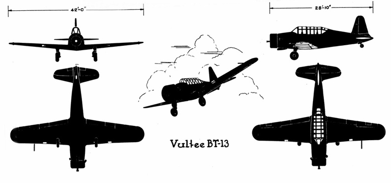 Vultee BT-13
Vultee BT-13 Front Side Perspective Bottom Top To meet the demand for a purely scouting machine, in which pilot and passenger shall have a clear fi...") Scouting Monoplane, with occupants below the wings.
Scouting Monoplane, with occupants below the wings.
To meet the demand for a purely scouting machine, in which pilot and passenger shall have a clear field for observation, both above and below, a monoplane has been designed which is called the “parasol.” This machine, a Morane-Saulnier, is shown. The two sustaining wings, forming a single surface, are raised above the body so that its occupants have nothing to impede their view earthward; and they can also see above them—an advantage of course in time of war, seeing that an enemy might be hovering overhead A. Engine and propeller B. Plane raised above hull C. Seats for pilot and passenger D. Rudder E. Elevating-plane. Douglas B-23
Front Side
...") Douglas B-23
Douglas B-23
Douglas B-23 Front Side Perspective Bottom Top (1506 visites) Scouting over the ruined region between the lines (no man’s land)") Scouting over the ruined region between the lines (no man’s land)
Scouting over the ruined region between the lines (no man’s land)
Scouting over the ruined region between the lines (no man’s land) The Bleriot Monoplane - top view showing its bird-like shape and the position of the pilot.") The Bleriot Monoplane - top view
The Bleriot Monoplane - top view
The Bleriot Monoplane - top view showing its bird-like shape and the position of the pilot. Gearless, 60 H.P. Gearless Transmission Co., Rochester, N. Y.
PRICE: $3,250
BODY: Side entr...") Gearless, 60 H.P
Gearless, 60 H.P
Gearless, 60 H.P. Gearless Transmission Co., Rochester, N. Y. PRICE: $3,250 BODY: Side entrance tonneau SEATS: 5 persons WEIGHT: 2,800 pounds WHEEL-BASE: 124 inches TREAD: 56 inches TIRES, FRONT: 36 × 4 inches TIRES, REAR: 36 × 4 inches STEERING: Worm and nut BRAKES: On transmission and rear hubs SPRINGS: Semi-elliptical FRAME: Pressed steel BORE: 5 in.; STROKE: 5 in. CYLINDERS: 4 vertical in front, 2 cycle MOTOR SUSPENSION: From sub-frame COOLING: Water IGNITION: Double jump spark CURRENT SUPPLY: Magneto and battery CARBURETER: Float-feed LUBRICATION: Mechanical force feed MOTOR-CONTROL: Spark and throttle CLUTCH: Expanding ring CHANGE GEAR: Gearless direct drive SPEEDS: 2 forward and reverse CHANGE-GEAR CONTROL: Side lever and foot pedal DRIVE: Shaft Martin B-10B
Front Side
...") Martin B-10B
Martin B-10B
Martin B-10B Front Side Perspective Bottom Top Douglas A-20B & C
Front Si...") Douglas A-20B & C
Douglas A-20B & C
Douglas A-20B & C Front Side Perspective Bottom Top Of famous aeroplanes at Rheims, five types stood out by themselves—the Farman, the Voisin, the Wri...") The Curtiss Biplane
The Curtiss Biplane
Of famous aeroplanes at Rheims, five types stood out by themselves—the Farman, the Voisin, the Wright, the Bleriot, and the Antoinette, all of which have been described. But there was one other, which few people had heard of before it appeared here. This was the Curtiss biplane, built by an American named Glenn H. Curtiss, and engined with a motor which also bore his name. Curtiss had experimented with many power-driven machines—motor-cycles, motor-cars, airships, and aeroplanes—and had won a prize in America with a small, light biplane, and it was a craft of this type—as seen in the figure —that he brought with him to Rheims, his idea being to compete for the speed prize. The machine had a front elevator and tail-planes, according to the practice in biplane construction; but an innovation was the setting of the ailerons midway between the main-planes—a position that will be noted in the sketch; another novelty was the way these ailerons operated. At the pilot’s back, as he sat in his driving seat, was an upright rod with two shoulder-pieces—by means of which, should he shift his body, he could swing the rod from side to side. Wires ran from the rod to the ailerons; and if the pilot leaned over, say, to the right, he drew down the ailerons on the left side of the machine. The merit of such a control was that it was instinctive; that is to say, should the biplane tip down on one side, it was natural for the pilot to lean away from the plane-ends that were sinking; and he operated the ailerons automatically, as he did this, and so brought the machine level again. A. Elevating-planes B. Pilot’s seat and control-wheel C.C. Main-planes D. Ailerons E. Motor and propeller F. Tail-plane and rudder. An aeroplpane in war") An aeroplpane in war
An aeroplpane in war
An aeroplpane in war Fairchild PT-19
Front Side...") Fairchild PT-19
Fairchild PT-19
Fairchild PT-19 Front Side Perspective Bottom Top R & L Stanhope. Rauch and Lang Carriage Co., Cleveland, Ohio
PRICE: $1,850
BODY: Stanhope
...") R & L Stanhope
R & L Stanhope
R & L Stanhope. Rauch and Lang Carriage Co., Cleveland, Ohio PRICE: $1,850 BODY: Stanhope SEATS: 2 persons WEIGHT: 1,600 pounds WHEEL-BASE: 73 inches TIRES, FRONT: 32 in., pneumatic TIRES, REAR: 32 in., pneumatic STEERING: Side lever BRAKES: On rear wheels and emergency SPRINGS: Semi-elliptic front; full elliptic rear FRAME: Steel HORSE-POWER: 1½ MOTOR: Hertner MOTOR SUSPENSION: Under body SPEED: 1–22 m. p. h. DISTANCE: 75 to 80 miles MOTOR-CONTROL: Lever at left of seat DRIVE: Double chain from countershaft A. Lower part of aeroplane’s hull
B. Revolving barrel to which bombs are clipped
C. Bombs
D. Re...") Bomb-releasing mechanism
Bomb-releasing mechanism
A. Lower part of aeroplane’s hull B. Revolving barrel to which bombs are clipped C. Bombs D. Releasing mechanism operated by marksman in machine. Bombs may be carried and dropped when opportunity offers; and as an improvement upon the early method, which was simply to throw these from the machine, there are releasing mechanisms now devised which carry a number of projectiles and drop them one by one as a lever is moved. The bombs, which are long, pointed, and balanced so that they will fall head first, are clipped round a barrel rather like that of a revolver, which is fixed beneath the aeroplane’s hull just below the occupants’ seat. Mechanism causes the carrying chamber to revolve and bring each bomb against a releasing catch, which—at a movement of the marksman’s lever—throws it outwards and downward. Plane going down in flames") Plane going down in flames
Plane going down in flames
Plane going down in flames Bell P-39C & D
Front Side ...") Bell P-39C & D
Bell P-39C & D
Bell P-39C & D Front Side Perspective Bottom Top Showing near-side “Boot.”
Coaches with \"Boots\"
From Coach and Sedan, we obtain a quaint bu...") Coach of Queen Elizabeth’s Ladies
Coach of Queen Elizabeth’s Ladies
Showing near-side “Boot.” Coaches with "Boots" From Coach and Sedan, we obtain a quaint but fairly graphic description of the coach of this period:— “The coach was a thick, burly, square-set fellow in a doublet of black leather, brasse button’d down the breast, back, sleeves and wings, with monstrous wide boots, fringed at the top with a net fringe, and a round breech (after the old fashion) gilded, and on his back an atchievement of sundry coats [of arms], in their proper colours.” The “boots” were projections at the sides of the body between the front and back wheels, as shown in the drawing of the coach occupied by Queen Elizabeth’s ladies; and there is much evidence to support the opinion that these boots were not covered. Republic P-35
Front Side
...") Republic P-35
Republic P-35
Republic P-35 Front Side Perspective Bottom Top") Plan of typical New Haven sharpie showing design and construction characteristics
Plan of typical New Haven sharpie showing design and construction characteristics Hercules, Model 101. James Macnaughtan Co., Buffalo, N. Y.
PRICE: $2,000
BODY: Closed deliv...") Hercules, Model 101
Hercules, Model 101
Hercules, Model 101. James Macnaughtan Co., Buffalo, N. Y. PRICE: $2,000 BODY: Closed delivery wagon CAPACITY: 1,000 pounds WEIGHT: 2,700 pounds TIRES, FRONT: 34 × 2 inches TIRES, REAR: 36 × 2 inches STEERING: Horizontal side lever BRAKES: Internal expanding hub SPRINGS: Front, half platform; rear, full elliptical MOTORS: Single equipment MOTOR SUSPENSION: From body MOTOR-CONTROL: Westinghouse CHANGE SPEEDS: 4 forward and reverse DRIVE: Double chain Douglas A-24
Front Side
...") Douglas A-24
Douglas A-24
Douglas A-24 Front Side Perspective Bottom Top Northrop A-17
Front Side
...") Northrop A-17
Northrop A-17
Northrop A-17 Front Side Perspective Bottom Top Air raid siren in Paris") Tooting the sirens of warning
Tooting the sirens of warning
Air raid siren in Paris By 1903 the Wright Brothers were ready to build a powered man-carrying flying machine. Their experim...") Wright Brothers first powered airplane
Wright Brothers first powered airplane
By 1903 the Wright Brothers were ready to build a powered man-carrying flying machine. Their experiments had shown them just how much moving air was necessary to create lift in such a machine. To create the needed thrust, an engine having eight horsepower and weighing not over 200 pounds had to be fitted into the machine. Such an engine was not available, so the Wrights built one in their shop at Dayton, Ohio. They were ready to ship their airplane to Kitty Hawk, N. C., in the fall of 1903. Belden, 30 H.P. Belden Auto Co., Pittsburgh, Pa.
PRICE: $4,500
BODY: Side entrance tonneau
...") Belden, 30 H.P
Belden, 30 H.P
Belden, 30 H.P. Belden Auto Co., Pittsburgh, Pa. PRICE: $4,500 BODY: Side entrance tonneau SEATS: 7 persons WEIGHT: 2,450 pounds WHEEL-BASE: 124 inches TREAD: 56 inches TIRES, FRONT: 36 × 3½ inches TIRES, REAR: 36 × 4½ inches STEERING: Worm and sector BRAKES: Two on rear hubs SPRINGS: Semi-elliptical front; platform rear FRAME: Pressed steel BORE: 5⅛ in.; STROKE: 5½ in. CYLINDERS: 4 vertical, in front VALVE ARRANGEMENT: Mechanical intake and exhaust MOTOR SUSPENSION: From side members of frame COOLING: Water; cellular radiator IGNITION: Jump spark CURRENT SUPPLY: Magneto and battery CARBURETER: Automatic LUBRICATION: Force feed MOTOR-CONTROL: Spark and throttle CLUTCH: Multiple disc CHANGE GEAR: Belden selective SPEEDS: 3 forward and reverse CHANGE-GEAR CONTROL: Side lever DRIVE: Shaft Republic P43-A
Front Side ...") Republic P43-A
Republic P43-A
Republic P43-A Front Side Perspective Bottom Top At the beginning of 1909 there were two types of successful aeroplane—the Wright and the Voisin. B...") The Voisin Biplane
The Voisin Biplane
At the beginning of 1909 there were two types of successful aeroplane—the Wright and the Voisin. Bleriot had flown with his monoplane and flown well; but he was still in the process of evolving a practical machine, and several other inventors were in a similar stage. It was the Wright and the Voisin which had proved their worth; and the Wright, as has been said, was the better of the two. Of the Voisin, as flown in 1909, a reproduction is given in the figure. It was a heavier aeroplane than the Wrights’, owing largely to the weight of its alighting gear (250 lbs.) and of its big balancing tail (more than 100 lbs.); hence the necessity for using a 50-h.p. motor, which drove a two-bladed metal propeller at the rate of 1200 revolutions a minute. The Voisin brothers, and other French makers, did not approve of the two-propeller system of the Wrights: they preferred one screw, revolving at high speed. But there was no doubt—at any rate in this stage of aviation—that the Wright method was more efficient than that of the Frenchmen. It was calculated, indeed, that the Wright biplane, when actually in the air, could be driven at an expenditure of only 15 h.p.; whereas the Voisin, even with its 50-h.p. motor running at full speed, had only just enough power to fly. A. Elevating plane B. Pilot’s seat C.C. Main-planes D. Engine and propeller E. Landing chassis F. Balancing tail G. Rudder. Ryan PT-22
Front Side
...") Ryan PT-22
Ryan PT-22
Ryan PT-22 Front Side Perspective Bottom Top North American P-51
Front ...") North American P-51
North American P-51
North American P-51 Front Side Perspective Bottom Top Sledges have played an important part in polar exploration, and were used,in varying degree, by Sir ...") The Man-drawn sledge
The Man-drawn sledge
Sledges have played an important part in polar exploration, and were used,in varying degree, by Sir W.E.Parry , Sir John Franklin, and other early explorers of the Arctic. Douglas O-46A
Front Side
...") Douglas O-46A
Douglas O-46A
Douglas O-46A Front Side Perspective Bottom Top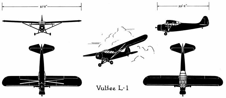 Vultee L-1
Vultee L-1 Front Side Perspective Bottom Top The seaplane shoots off the catapult") The seaplane shoots off the catapult
The seaplane shoots off the catapult
The seaplane shoots off the catapult Frontenac Runabout, Model D, 40–45 H.P. Abendroth and Root M'f'g. Co., Newburgh, N. Y.
PRI...") Frontenac Runabout, Model D, 40–45 H.P
Frontenac Runabout, Model D, 40–45 H.P
Frontenac Runabout, Model D, 40–45 H.P. Abendroth and Root M'f'g. Co., Newburgh, N. Y. PRICE: $3,500 BODY: Runabout SEATS: 3 persons WEIGHT: 2,500 pounds WHEEL-BASE: 123 inches TREAD: 56 inches TIRES, FRONT: 36 × 3½ in. TIRES, REAR: 36 × 4½ in. STEERING: Bevel gear and shaft connecting to worm and nut BRAKES: External and internal on rear wheels SPRINGS: Semi-elliptical FRAME: Pressed steel BORE: 4¾ in.; STROKE: 5 in. CYLINDERS: 4 vertical, in pairs VALVE ARRANGEMENT: On one side MOTOR SUSPENSION: Sub-frame COOLING: Water; fin tube radiator IGNITION: Jump spark (double) CURRENT SUPPLY: Magneto and battery CARBURETER: Automatic float-feed LUBRICATION: Splash MOTOR-CONTROL: Spark and throttle CHANGE GEAR: Sliding type SPEEDS: 3 forward and reverse CHANGE-GEAR CONTROL: Selective system DRIVE: Shaft Sovereign, Model M. Matthews Motor Co., Camden, N. J.
BODY: Side entrance tonneau
SEATS: 8 ...") Sovereign, Model M
Sovereign, Model M
Sovereign, Model M. Matthews Motor Co., Camden, N. J. BODY: Side entrance tonneau SEATS: 8 persons WHEEL-BASE: 124 inches TREAD: 56 inches TIRES, FRONT: 36 × 4 inches TIRES, REAR: 36 × 5 inches BRAKES: 2 double internal on rear hubs SPRINGS: Semi-elliptic, front; platform type rear FRAME: Pressed steel BORE: 5½ in.; STROKE: 6 in. CYLINDERS: 4 vertical MOTOR SUSPENSION: From frame COOLING: Water IGNITION Jump spark (double plugs) CURRENT SUPPLY: Magneto and batteries CARBURETER: Automatic LUBRICATION: Mechanical pump MOTOR-CONTROL: Spark and throttle CHANGE GEAR: Sliding type SPEEDS: 4 forward and reverse CHANGE-GEAR CONTROL: Side lever DRIVE: Double side chain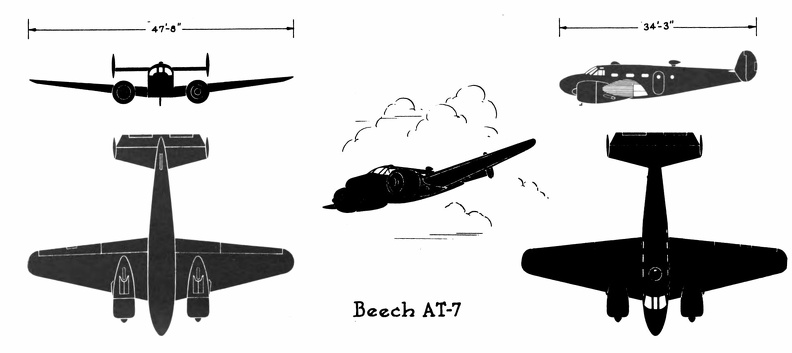 Beech AT-7
Beech AT-7 Front Side Perspective Bottom Top Beech AT-10
Front Side
Perspective
Bottom ...") Beech AT-10
Beech AT-10
Beech AT-10 Front Side Perspective Bottom Top Republic AT-12
Front Side ...") Republic AT-12
Republic AT-12
Republic AT-12 Front Side Perspective Bottom Top Curtiss C-46
Front Side
...") Curtiss C-46
Curtiss C-46
Curtiss C-46 Front Side Perspective Bottom Top Consolidated OA-10
Front S...") Consolidated OA-10
Consolidated OA-10
Consolidated OA-10 Front Side Perspective Bottom Top The Dreadnaught") The Dreadnaught
The Dreadnaught
The Dreadnaught North American AT-6A
Front  ...") North American AT-6A
North American AT-6A
North American AT-6A Front Side Perspective Bottom Top The Snow. an obsolete type") The Snow. an obsolete type
The Snow. an obsolete type
The Snow. an obsolete type Hercules, Model 139. James Macnaughtan Co., Buffalo, N. Y.
PRICE: $2,250
BODY: Express wago...") Hercules, Model 139
Hercules, Model 139
Hercules, Model 139. James Macnaughtan Co., Buffalo, N. Y. PRICE: $2,250 BODY: Express wagon CAPACITY: 2,000 pounds WEIGHT: 3,200 pounds TIRES, FRONT: 34 × 3½ inches TIRES, REAR: 36 × 4 inches STEERING: Horizontal side lever BRAKES: Internal expanding hub SPRINGS: Front, half platform; rear, full elliptic MOTORS: Single equipment MOTOR SUSPENSION: From body DISTANCE: 50 miles MOTOR-CONTROL: Westinghouse SPEED: 9 m.p.h. CHANGE SPEEDS: 4 speeds ahead and reverse DRIVE: Double chain Aviators taking photographs") Aviators taking photographs
Aviators taking photographs
Aviators taking photographs The Waterfront of New York") Waterfront
Waterfront
The Waterfront of New York Martin A-30
Front Side
...") Martin A-30
Martin A-30
Martin A-30 Front Side Perspective Bottom Top A Stage Coach of the Eighteenth Century") A Stage Coach of the Eighteenth Century
A Stage Coach of the Eighteenth Century
A Stage Coach of the Eighteenth Century For the fisheries a multitude of smaller types were constructed—such as the lugger, the shallop, t...") The Bug-Eye
The Bug-Eye
For the fisheries a multitude of smaller types were constructed—such as the lugger, the shallop, the sharpie, the bug-eye, the smack. showing the spread of the planes and tail, and the delicate taper of the long, canoe-shaped body.") The Antoinette Monoplane - top view
The Antoinette Monoplane - top view
showing the spread of the planes and tail, and the delicate taper of the long, canoe-shaped body. Taking it in his jaws") Taking it in his jaws
Taking it in his jaws
Taking it in his jaws North American O-47A & B
Front &...") North American O-47A& B
North American O-47A& B
North American O-47A & B Front Side Perspective Bottom Top Douglas XB-19
Front Side
...") Douglas XB-19
Douglas XB-19
Douglas XB-19 Front Side Perspective Bottom Top The Train Ferry carries entire trains across rivers where there are no bridges. Some of the largest ...") The Train Ferry
The Train Ferry
The Train Ferry carries entire trains across rivers where there are no bridges. Some of the largest train boats have several tracks and carry a train on each. The boats are tied in slips at the shore so that the tracks meet exactly those on the land. The story of Dædalus and Icarus also tells us that man believed flying was somehow possible. Dædal...") Daedalus and Icarus
Daedalus and Icarus
The story of Dædalus and Icarus also tells us that man believed flying was somehow possible. Dædalus was a very clever man who lived with his son Icarus on the Island of Crete. The king of this island requested Dædalus to build a labyrinth or maze for him. Dædalus constructed the labyrinth so cleverly that only the king, who had the clue to the winding passages, could find his way out. One day the king became very angry at Dædalus and threw both him and his son Icarus into the labyrinth, intending that they should perish. Dædalus, who had been dreaming of flying, fashioned wings from wax and feathers, with which he and Icarus could fly to freedom. He cautioned Icarus that he must not fly too high or the sun would melt the wax in his wings. Icarus, impatient to escape, scarcely listened. Like birds the two flew into the air, quickly leaving the walls of the labyrinth. Dædalus, flying low, safely crossed the sea and reached Sicily. Icarus, unfortunately, failed to heed his father’s warning. Flying was so much fun that he rose higher and higher. Suddenly feathers began to drop one by one. Too late Icarus realized that the sun had melted the wax in his wings. Down, down he fell into the sea. It is also important to know, if you have to go through or along somewhere close with your car, what...") Room to pass
Room to pass
It is also important to know, if you have to go through or along somewhere close with your car, what width you need. That can become such a certainty for you that it will look like virtuosity to the uninitiated. It's a matter of routine, of course, but it can be extremely practiced. It must be started with calculating the extreme points of the fenders. Later on, even this aid is often redundant. The best way to learn this is to place two blocks of wood on the ground, or to drive two posts, which are measured just the width of the wagon apart. Riding on that is the means of learning to estimate a narrow passage. Is the width wide enough to pass, but what When measured tight, keep flat on the side of the traffic obstruction, which is on your and steering wheel side. After all, here you can see exactly how close you can get without the risk of a collision. The other side will then be free of itself. [Translated online from the Dutch ] Schooner rigged Sharpie
For the fisheries a multitude of smaller types were constructed—such as ...") Schooner rigged Sharpie
Schooner rigged Sharpie
Schooner rigged Sharpie For the fisheries a multitude of smaller types were constructed—such as the lugger, the shallop, the sharpie, the bug-eye, the smack. Naval battle with planes launched from ships") Naval battle with planes launched from ships
Naval battle with planes launched from ships
Naval battle with planes launched from ships Chicago 6-Ton Coal Truck. Chicago Commercial Auto Mfg. Co., Chicago, Ill.
BODY: Side deliver...") Chicago 6-Ton Coal Truck
Chicago 6-Ton Coal Truck
Chicago 6-Ton Coal Truck. Chicago Commercial Auto Mfg. Co., Chicago, Ill. BODY: Side delivery CAPACITY: 12,000 pounds WHEEL-BASE: 126 inches TREAD: 64 inches TIRES, FRONT: 36 inches, solid rubber TIRES, REAR: 36 inches, solid rubber STEERING: Vertical column BRAKES: On transmission shaft and rear wheels SPRINGS: Platform type FRAME: Steel BORE: 6 inches STROKE: 6 inches CYLINDERS: 4, cast separate VALVE ARRANGEMENT: In cylinder heads, operated from one side MOTOR SUSPENSION: Under cab COOLING: Water IGNITION: Jump Spark CURRENT SUPPLY: Batteries or magneto CARBURETER: Float-feed type LUBRICATION: Mechanical force feed MOTOR-CONTROL: Spark and throttle CLUTCH: Cast steel bands with graphite inserts CHANGE GEAR: Sliding type SPEEDS: 3 forward and reverse CHANGE-GEAR CONTROL: Side lever DRIVE: Side chains