


 Consolidated OA-10
Front S...") Consolidated OA-10
Consolidated OA-10
Consolidated OA-10 Front Side Perspective Bottom Top Naval battle with planes launched from ships") Naval battle with planes launched from ships
Naval battle with planes launched from ships
Naval battle with planes launched from ships A deckload of cotton") A deckload of cotton
A deckload of cotton
A deckload of cotton Beech AT-10
Front Side
Perspective
Bottom ...") Beech AT-10
Beech AT-10
Beech AT-10 Front Side Perspective Bottom Top showing the spread of the planes and tail, and the delicate taper of the long, canoe-shaped body.") The Antoinette Monoplane - top view
The Antoinette Monoplane - top view
showing the spread of the planes and tail, and the delicate taper of the long, canoe-shaped body. North American O-47A & B
Front &...") North American O-47A& B
North American O-47A& B
North American O-47A & B Front Side Perspective Bottom Top Martin A-30
Front Side
...") Martin A-30
Martin A-30
Martin A-30 Front Side Perspective Bottom Top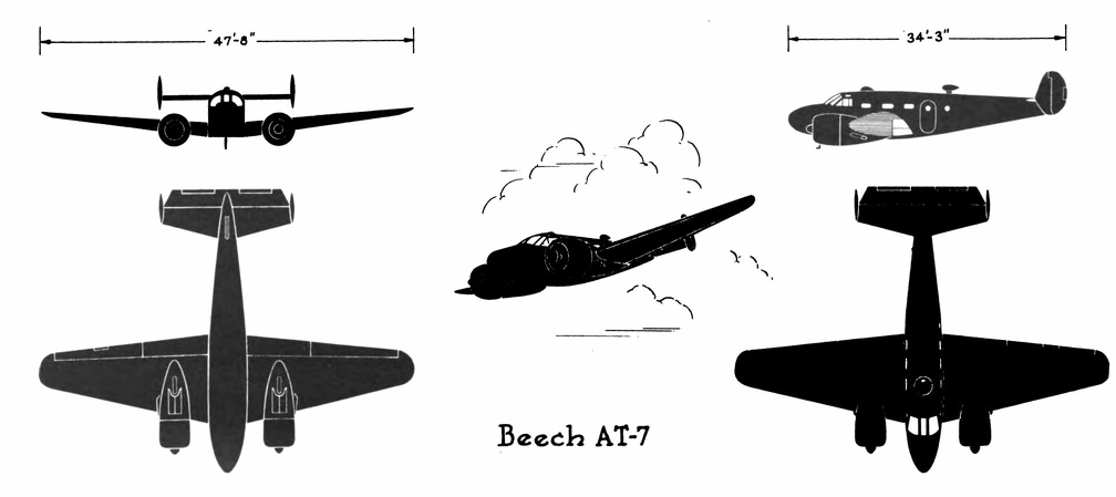 Beech AT-7
Beech AT-7 Front Side Perspective Bottom Top Curtiss C-46
Front Side
...") Curtiss C-46
Curtiss C-46
Curtiss C-46 Front Side Perspective Bottom Top Republic AT-12
Front Side ...") Republic AT-12
Republic AT-12
Republic AT-12 Front Side Perspective Bottom Top Ryan PT-22
Front Side
...") Ryan PT-22
Ryan PT-22
Ryan PT-22 Front Side Perspective Bottom Top Bell P-39C & D
Front Side ...") Bell P-39C & D
Bell P-39C & D
Bell P-39C & D Front Side Perspective Bottom Top North American AT-6A
Front  ...") North American AT-6A
North American AT-6A
North American AT-6A Front Side Perspective Bottom Top Aviators taking photographs") Aviators taking photographs
Aviators taking photographs
Aviators taking photographs A Stage Coach of the Eighteenth Century") A Stage Coach of the Eighteenth Century
A Stage Coach of the Eighteenth Century
A Stage Coach of the Eighteenth Century Dropping off in parachute from flaming balloon") Dropping off in parachute from flaming balloon
Dropping off in parachute from flaming balloon
Dropping off in parachute from flaming balloon Republic P43-A
Front Side ...") Republic P43-A
Republic P43-A
Republic P43-A Front Side Perspective Bottom Top The Waterfront of New York") Waterfront
Waterfront
The Waterfront of New York North American P-51
Front ...") North American P-51
North American P-51
North American P-51 Front Side Perspective Bottom Top At the beginning of 1909 there were two types of successful aeroplane—the Wright and the Voisin. B...") The Voisin Biplane
The Voisin Biplane
At the beginning of 1909 there were two types of successful aeroplane—the Wright and the Voisin. Bleriot had flown with his monoplane and flown well; but he was still in the process of evolving a practical machine, and several other inventors were in a similar stage. It was the Wright and the Voisin which had proved their worth; and the Wright, as has been said, was the better of the two. Of the Voisin, as flown in 1909, a reproduction is given in the figure. It was a heavier aeroplane than the Wrights’, owing largely to the weight of its alighting gear (250 lbs.) and of its big balancing tail (more than 100 lbs.); hence the necessity for using a 50-h.p. motor, which drove a two-bladed metal propeller at the rate of 1200 revolutions a minute. The Voisin brothers, and other French makers, did not approve of the two-propeller system of the Wrights: they preferred one screw, revolving at high speed. But there was no doubt—at any rate in this stage of aviation—that the Wright method was more efficient than that of the Frenchmen. It was calculated, indeed, that the Wright biplane, when actually in the air, could be driven at an expenditure of only 15 h.p.; whereas the Voisin, even with its 50-h.p. motor running at full speed, had only just enough power to fly. A. Elevating plane B. Pilot’s seat C.C. Main-planes D. Engine and propeller E. Landing chassis F. Balancing tail G. Rudder.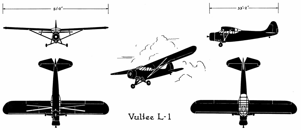 Vultee L-1
Vultee L-1 Front Side Perspective Bottom Top Republic P-35
Front Side
...") Republic P-35
Republic P-35
Republic P-35 Front Side Perspective Bottom Top Douglas O-46A
Front Side
...") Douglas O-46A
Douglas O-46A
Douglas O-46A Front Side Perspective Bottom Top Taking it in his jaws") Taking it in his jaws
Taking it in his jaws
Taking it in his jaws For the fisheries a multitude of smaller types were constructed—such as the lugger, the shallop, t...") The Bug-Eye
The Bug-Eye
For the fisheries a multitude of smaller types were constructed—such as the lugger, the shallop, the sharpie, the bug-eye, the smack. Schooner rigged Sharpie
For the fisheries a multitude of smaller types were constructed—such as ...") Schooner rigged Sharpie
Schooner rigged Sharpie
Schooner rigged Sharpie For the fisheries a multitude of smaller types were constructed—such as the lugger, the shallop, the sharpie, the bug-eye, the smack. The seaplane shoots off the catapult") The seaplane shoots off the catapult
The seaplane shoots off the catapult
The seaplane shoots off the catapult Northrop A-17
Front Side
...") Northrop A-17
Northrop A-17
Northrop A-17 Front Side Perspective Bottom Top Douglas A-24
Front Side
...") Douglas A-24
Douglas A-24
Douglas A-24 Front Side Perspective Bottom Top The Snow. an obsolete type") The Snow. an obsolete type
The Snow. an obsolete type
The Snow. an obsolete type Fairchild PT-19
Front Side...") Fairchild PT-19
Fairchild PT-19
Fairchild PT-19 Front Side Perspective Bottom Top Douglas A-20B & C
Front Si...") Douglas A-20B & C
Douglas A-20B & C
Douglas A-20B & C Front Side Perspective Bottom Top The Dreadnaught") The Dreadnaught
The Dreadnaught
The Dreadnaught To meet the demand for a purely scouting machine, in which pilot and passenger shall have a clear fi...") Scouting Monoplane, with occupants below the wings.
Scouting Monoplane, with occupants below the wings.
To meet the demand for a purely scouting machine, in which pilot and passenger shall have a clear field for observation, both above and below, a monoplane has been designed which is called the “parasol.” This machine, a Morane-Saulnier, is shown. The two sustaining wings, forming a single surface, are raised above the body so that its occupants have nothing to impede their view earthward; and they can also see above them—an advantage of course in time of war, seeing that an enemy might be hovering overhead A. Engine and propeller B. Plane raised above hull C. Seats for pilot and passenger D. Rudder E. Elevating-plane. Of famous aeroplanes at Rheims, five types stood out by themselves—the Farman, the Voisin, the Wri...") The Curtiss Biplane
The Curtiss Biplane
Of famous aeroplanes at Rheims, five types stood out by themselves—the Farman, the Voisin, the Wright, the Bleriot, and the Antoinette, all of which have been described. But there was one other, which few people had heard of before it appeared here. This was the Curtiss biplane, built by an American named Glenn H. Curtiss, and engined with a motor which also bore his name. Curtiss had experimented with many power-driven machines—motor-cycles, motor-cars, airships, and aeroplanes—and had won a prize in America with a small, light biplane, and it was a craft of this type—as seen in the figure —that he brought with him to Rheims, his idea being to compete for the speed prize. The machine had a front elevator and tail-planes, according to the practice in biplane construction; but an innovation was the setting of the ailerons midway between the main-planes—a position that will be noted in the sketch; another novelty was the way these ailerons operated. At the pilot’s back, as he sat in his driving seat, was an upright rod with two shoulder-pieces—by means of which, should he shift his body, he could swing the rod from side to side. Wires ran from the rod to the ailerons; and if the pilot leaned over, say, to the right, he drew down the ailerons on the left side of the machine. The merit of such a control was that it was instinctive; that is to say, should the biplane tip down on one side, it was natural for the pilot to lean away from the plane-ends that were sinking; and he operated the ailerons automatically, as he did this, and so brought the machine level again. A. Elevating-planes B. Pilot’s seat and control-wheel C.C. Main-planes D. Ailerons E. Motor and propeller F. Tail-plane and rudder. Plane going down in flames") Plane going down in flames
Plane going down in flames
Plane going down in flames A. Lower part of aeroplane’s hull
B. Revolving barrel to which bombs are clipped
C. Bombs
D. Re...") Bomb-releasing mechanism
Bomb-releasing mechanism
A. Lower part of aeroplane’s hull B. Revolving barrel to which bombs are clipped C. Bombs D. Releasing mechanism operated by marksman in machine. Bombs may be carried and dropped when opportunity offers; and as an improvement upon the early method, which was simply to throw these from the machine, there are releasing mechanisms now devised which carry a number of projectiles and drop them one by one as a lever is moved. The bombs, which are long, pointed, and balanced so that they will fall head first, are clipped round a barrel rather like that of a revolver, which is fixed beneath the aeroplane’s hull just below the occupants’ seat. Mechanism causes the carrying chamber to revolve and bring each bomb against a releasing catch, which—at a movement of the marksman’s lever—throws it outwards and downward. Douglas B-23
Front Side
...") Douglas B-23
Douglas B-23
Douglas B-23 Front Side Perspective Bottom Top Republic P-47B
Front Side ...") Republic P-47B
Republic P-47B
Republic P-47B Front Side Perspective Bottom Top Martin B-10B
Front Side
...") Martin B-10B
Martin B-10B
Martin B-10B Front Side Perspective Bottom Top Douglas B-18A
Front Side
...") Douglas B-18A
Douglas B-18A
Douglas B-18A Front Side Perspective Bottom Top Air raid siren in Paris") Tooting the sirens of warning
Tooting the sirens of warning
Air raid siren in Paris Cessna AT-8
Front Side
...") Cessna AT-8
Cessna AT-8
Cessna AT-8 Front Side Perspective Bottom Top The Bleriot Monoplane - top view showing its bird-like shape and the position of the pilot.") The Bleriot Monoplane - top view
The Bleriot Monoplane - top view
The Bleriot Monoplane - top view showing its bird-like shape and the position of the pilot.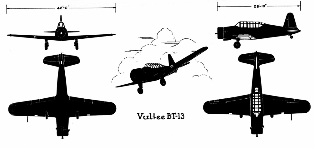 Vultee BT-13
Vultee BT-13 Front Side Perspective Bottom Top (1390 visits) Scouting over the ruined region between the lines (no man’s land)") Scouting over the ruined region between the lines (no man’s land)
Scouting over the ruined region between the lines (no man’s land)
Scouting over the ruined region between the lines (no man’s land) An aeroplpane in war") An aeroplpane in war
An aeroplpane in war
An aeroplpane in war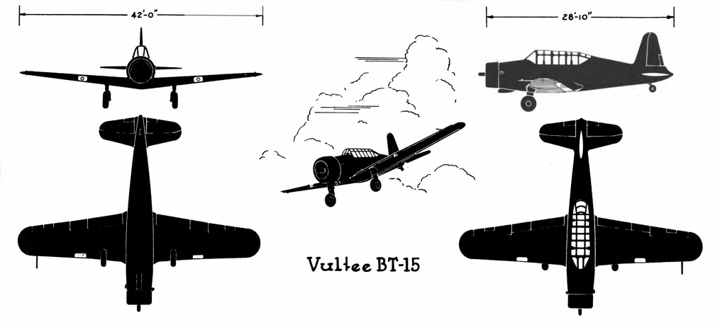 Vultee BT-15
Vultee BT-15 Front Side Perspective Bottom Top Martin B-26 B& C
Front Sid...") Martin B-26 B& C
Martin B-26 B& C
Martin B-26 B& C Front Side Perspective Bottom Top Douglas C-47
Front Side
...") Douglas C-47
Douglas C-47
Douglas C-47 Front Side Perspective Bottom Top Vultee A-31
Front Side
...") Vultee A-31
Vultee A-31
Vultee A-31 Front Side Perspective Bottom Top North American B-25 C & D
Front ...") North American B-25 C & D
North American B-25 C & D
North American B-25 C & D Front Side Perspective Bottom Top Shortly after the Harpers Ferry bridge reconstruction, Bollman was made foreman of bridges. It is ap...") Plan of Harpers Ferry Bridge
Plan of Harpers Ferry Bridge
Shortly after the Harpers Ferry bridge reconstruction, Bollman was made foreman of bridges. It is apparent that, on the basis of his practical ability, enhanced by the theoretical knowledge gained by intense self-study, he eventually came to assist Chief Engineer Benjamin H. Latrobe in bridge design. He later took this work over entirely as Latrobe’s attentions and talents were demanded in the location and extension of the line between Cumberland and Wheeling. While in Paris, President Yerkes, of the North Chicago Street Railway Company, purchased a noiseless...") A Steam Street Railway Motor
A Steam Street Railway Motor
While in Paris, President Yerkes, of the North Chicago Street Railway Company, purchased a noiseless steam motor, the results in experimenting with which will be watched with great interest. The accompanying engraving, for which we are indebted to the Street Railway Review, gives a very accurate idea of the general external appearance. The car is all steel throughout, except windows, doors, and ceiling. It is 12 ft. long, 8 ft. wide, and 9 ft. high, and weighs about seven tons. The engines, which have 25 horsepower and are of the double cylinder pattern, are below the floor and connected directly to the wheels. The wheels are four in number and 31 in. in diameter. The internal appearance and general arrangement of machinery, etc., is about that of the ordinary steam dummy. It will run in either direction, and the exhaust steam is run through a series of mufflers which suppress the sound, condense the steam and return the water to the boiler, which occupies the center of the car. The motor was built in Ghent, Belgium, and cost about $5,000, custom house duties amounting to about $2,000 more. Beech AT-11
Front Side
Perspective
Bottom ...") Beech AT-11
Beech AT-11
Beech AT-11 Front Side Perspective Bottom Top Douglas B-18
Front Side
...") Douglas B-18
Douglas B-18
Douglas B-18 Front Side Perspective Bottom Top I will now give you a sectional division of a first-rate line-of-battle ship. Such a ship, carrying ...") Section of First-rate Man-of-War
Section of First-rate Man-of-War
I will now give you a sectional division of a first-rate line-of-battle ship. Such a ship, carrying 120 or more guns, has four decks on which her guns are placed. The highest is open to the air, and is called the UPPER DECK At the after part, extending a little way beyond the mizen-mast, there is a raised platform, called the POOP. It has no guns on it. On the main deck is the steering-wheel, with the binnacle in front of it. The after part of this deck between the poop and the main-mast is called the quarter-deck, and is the place where the officers especially walk. The part under the poop is divided into cabins, appropriated to the use of the captain. Here, also, is a clerk's office and a pantry. Between the main and fore-mast the large boats are stowed, and on either side are the gangways at which sentries are stationed. The next deck under this is called the MAIN DECK. In the after part is the admiral's cabin. Immediately under the boats is a pen for the officers' live-stock ; and just abaft the fore-mast is the galley, or kitchen. The third deck from the upper is called the MIDDLE DECK. The after part is fitted up for the lieutenants, chaplain, surgeon, paymaster, marine officers, &c., and called the WARD-ROOM. In the fore part of the deck is placed the sick-bay, a compartment fitted up as a hospital ; about the centre of this deck is one of the capstans. The fourth from the upper is called the LOWER or GUN DECK. In the after part is the GUN-ROOM, where the midshipmen, and other junior officers, mess. The tiller of the rudder works through the gun-room just above their heads. A second capstan is placed on this deck ; and forward are the riding-bitts for securing the cables. It is the lowest deck on which guns are carried. The ORLOP DECK is the fifth deck from the upper. It has no guns or ports, though lighted up by bull's eyes or scuttles. In the after part is the purser's issue-room ; next to it is the after cockpit, where the midshipmen and other junior officers sleep in hammocks. Before it again will be found the sail-room, where the sails are kept, and the cable-tiers, where the cables are stowed. Before it again, just abaft the fore-mast, is the fore cockpit, and the warrant officers' cabins, while right in the head of the ship are the carpenter's and boatswain's stores. Low as we have got, we have still further to go down to the HOLD, which, if it may be so called, is the sixth deck from the highest. It is often divided into two decks for the greater convenience of stowage. Here are the FORE AND AFTER MAGAZINES, WATER TANKS, WINE AND SPIRIT ROOM, CHAIN CABLE LOCKERS, SHOT LOCKERS, BREAD ROOM, SHELL ROOM, GUNNER'S STORE ROOM, DRY PROVISION, and BEEF AND PORK IN CASKS. Since the introduction of auxiliary steam-power into ships of war, a large portion of the hold is devoted to the steam-engine and boilers, coal bunkers, and the shaft of the screw, while the funnel runs up through all the decks ; but it is wonderful, comparatively, how little space these are allowed to occupy, considering the great aid the steam-engine affords to the movements of the ship. A coastal sea-plane, as now planned, is a craft having, say, two engines, each devolving 120 h.p., w...") Sea-plane to carry a crew of seven
Sea-plane to carry a crew of seven
A coastal sea-plane, as now planned, is a craft having, say, two engines, each devolving 120 h.p., with a wing span of some 80 feet, and an accommodation in its hull for three men—the pilot, a combatant with a machine-gun, and an observer with an installation of wireless. But types are changing constantly, and the tendency is to build larger craft. A machine weighing a couple of tons is shown, and a novelty in regard to it is that it has wheels upon either side of its boat-shaped car, upon which it can move on land, and which fold upward when it rests upon the water. A. Hull upon which the machine floats when in the sea B.B.B. Wheels upon which it may move when on land, and which fold upward when it is on the water C. Pilot’s controlling wheel D.D. Main sustaining planes E. Four-bladed propeller driven by chain-gearing from engine within the hull. The ketch was a two-master, sometimes rigged with lanteen sails, but more often with the foremast sq...") The Ketch
The Ketch
The ketch was a two-master, sometimes rigged with lanteen sails, but more often with the foremast square-rigged, like a ship's foremast, and the mainmast like the mizzen of a modern bark, with a square topsail surmounting a fore-and-aft mainsail. The foremast was set very much aft—often nearly amidships. Already, anticipating war in the air, a fighting aeroplane has been evolved; and a machine of this t...") The Vickers
The Vickers
Already, anticipating war in the air, a fighting aeroplane has been evolved; and a machine of this type is shown in Figure. The body, in which pilot and gunner sit, is armoured lightly with plates which will resist the penetration of a bullet. Such armouring was found necessary after the use of aeroplanes in Tripoli and the Balkans. When flying unavoidably low in these campaigns, and when fired at from the ground, the wooden bodies of machines were pierced by shot, and in several instances their occupants wounded. A fighting aeroplane A. Machine-gun projecting from opening in bow B. Gunner’s position C. Pilot’s seat D.D. Side windows for observation E. Engine and propeller.