


 Curtiss AT-9
Front Side
...") Curtiss AT-9
Curtiss AT-9
Curtiss AT-9 Front Side Perspective Bottom Top Curtiss C-46
Front Side
...") Curtiss C-46
Curtiss C-46
Curtiss C-46 Front Side Perspective Bottom Top Curtiss P-40E
Front Side
...") Curtiss P-40E
Curtiss P-40E
Curtiss P-40E Front Side Perspective Bottom Top Biplane (537 visites) A. Hull, which is steel-built, containing pilot and passenger
B. Main-planes—the lower at a dihed...") D.F.W. (German-designed) Biplane
D.F.W. (German-designed) Biplane
A. Hull, which is steel-built, containing pilot and passenger B. Main-planes—the lower at a dihedral angle C. Uptilted stabilising ailerons, which may be locked in position D. Stabilising fin E. Rudder F. Elevating-plane G. 100-h.p. motor (which is enclosed) and propeller. A method of flying was suggested as long ago as 1744, by the inventor De Bacqueville; his plan was ...") De Bacqueville
De Bacqueville
A method of flying was suggested as long ago as 1744, by the inventor De Bacqueville; his plan was to fix four planes or wings to his hands and feet, and then propel himself through the air by vigorous motions of his arms, and kickings of his legs. He made a flight from a balcony overlooking a river, but finished his trial ingloriously by falling into a barge. Such schemes, indeed, were doomed to failure; and they are only interesting because they show how, even in those far-off days, men were ready to risk their lives in attempts to conquer the air. Diagram comparing the Pioneer (shaded drawing) with the Columbia, a standard 8-wheel engine of 1851....") Diagram comparing the Pioneer with the Columbia
Diagram comparing the Pioneer with the Columbia
Diagram comparing the Pioneer (shaded drawing) with the Columbia, a standard 8-wheel engine of 1851. (Drawing by J. H. White.) Columbia Hudson River Railroad Lowell Machine Shop, 1852 Wt. 271/2 tons (engine only) Cyl. 161/2 x 22 inches Wheel diam. 84 inches Pioneer Cumberland Valley Railroad Seth Wilmarth, 1851 121/2 tons 81/2 x 14 inches 54 inches Douglas A-20B & C
Front Si...") Douglas A-20B & C
Douglas A-20B & C
Douglas A-20B & C Front Side Perspective Bottom Top Douglas A-24
Front Side
...") Douglas A-24
Douglas A-24
Douglas A-24 Front Side Perspective Bottom Top Douglas B-18
Front Side
...") Douglas B-18
Douglas B-18
Douglas B-18 Front Side Perspective Bottom Top Douglas B-18A
Front Side
...") Douglas B-18A
Douglas B-18A
Douglas B-18A Front Side Perspective Bottom Top Douglas B-23
Front Side
...") Douglas B-23
Douglas B-23
Douglas B-23 Front Side Perspective Bottom Top Douglas C-39
Front Side
...") Douglas C-39
Douglas C-39
Douglas C-39 Front Side Perspective Bottom Top Douglas C-47
Front Side
...") Douglas C-47
Douglas C-47
Douglas C-47 Front Side Perspective Bottom Top Douglas C-54A
Front Side
...") Douglas C-54A
Douglas C-54A
Douglas C-54A Front Side Perspective Bottom Top Douglas O-46A
Front Side
...") Douglas O-46A
Douglas O-46A
Douglas O-46A Front Side Perspective Bottom Top Douglas XB-19
Front Side
...") Douglas XB-19
Douglas XB-19
Douglas XB-19 Front Side Perspective Bottom Top Drasina
This novel vehicle, under the name of \" Drasina was introduced into England in 1818, and, a...") Drasina
Drasina
Drasina This novel vehicle, under the name of " Drasina was introduced into England in 1818, and, at first, the greatest possible expectations were created, with regard to its usefulness and speed. It was maintained, that it would travel up-hill on a post-road as fast as a man could walk ; that on a level, even after a heavy rain, it would average six or seven miles an hour ; and that, on a descent, it would equal a horse at fall speed. It was described in the advertisements of the day as " consisting of two wheels, one behind the other, connected by a perch, on which a saddle is placed as a seat. The front wheel is made to turn on a pivot, guided by a circular lever or rudder, which comes op to the hand; the fore-arms rest on a cushion in front ; in this position, both hands holding the rudder firmly, the machine and traveller are preserved in equilibrio. In 1821 Lewis Gomperta of Surrey, introduced some decided improvements upon the Drasina , as will be seen from the accompanying engraving. The object of the improvement of Gomperta was to bring the arms of the rider into action, in assist-ance to his legs. It consisted " in the application of a handle, C, which is to be worked backwards and forwards, to which is attached a circular rack, D G, which works in a pinion, E, with ratch wheel on the ont wheel of the velocipede, and which, on being pulled by the rider with both hands, sends the machine forward; and when thrust from him does not send it back again, on account of the ratch, which allows the pinion to turn in that direction, free of the wheel. H is the saddle, and the rest, B is so made that the breast of the rider bears against it, while the sides come around him at some distance below the arms, and is stuffed." The rider could with this machine either propel it entirely without the feet, or he could use the feet, while the arms were free. The beam, A, was made of beech wood, and a pivot at F, allowed the front wheel to be turned to the right or left at the will of the rider. Drawing of 1885 Benz engine, showing
similarity in general appearance to Duryea engine. From
Karl ...") Drawing of 1885 Benz engine
Drawing of 1885 Benz engine
Drawing of 1885 Benz engine, showing similarity in general appearance to Duryea engine. From Karl Benz und sein Lebenswerk, Stuttgart, 1953. (Daimler-Benz Company publication.) Car driving by horses on the road") Driving on the road
Driving on the road
Car driving by horses on the road In the picture the operator is seen in the driving seat; and near him will be observed the motor whi...") Driving seat of Wright Biplane
Driving seat of Wright Biplane
In the picture the operator is seen in the driving seat; and near him will be observed the motor which drives the craft. In his left hand—that is to say in the one nearest us—he grasps the lever which operates the elevating planes. The rod from lever to plane can be seen, and the motions the pilot makes are these: should he wish to rise, he draws the lever towards him and tilts up the elevating planes in the manner already described, increasing the lifting power of the main-planes and so causing the machine to ascend; by a reverse movement of the lever—by pushing it away from him, that is to say—he makes the craft glide downward.") Driving-seat of a touring plane
Driving-seat of a touring plane Dropping off in parachute from flaming balloon") Dropping off in parachute from flaming balloon
Dropping off in parachute from flaming balloon
Dropping off in parachute from flaming balloon Another machine which is stable in flight, owing to the peculiar formation of its wings, which resis...") Dunne inherently stable Biplane
Dunne inherently stable Biplane
Another machine which is stable in flight, owing to the peculiar formation of its wings, which resist a diving or plunging movement, or a lateral swing, is the Dunne biplane—as designed by Lieutenant J. W. Dunne. This craft is seen in the figure. Using such a machine, pilots have flown for long distances with the control levers locked, the biplane adapting itself automatically to the wind-gusts and preserving its equilibrium without aid of any kind. It has neither fore-plane nor tail; it is made to ascend by elevators which are in the form of hinged flaps, or ailerons, and is steered by two rudders at the extremities of the main-planes. A. Hull containing pilot and passenger B.B. Main-planes C.C.C.C. Flaps used as elevators D.D. Side-planes which act as rudders E. Engine and propeller F. Alighting gear. Description of first trip in the car
When I got this car ready to run one night, I took it out a...") Duryea Automobile
Duryea Automobile
Description of first trip in the car When I got this car ready to run one night, I took it out and I had a young fellow with me; I thought I might need him to help push in case the car didn't work…. We ran from the area of the shop where it was built down on Taylor Street. We started out and ran up Worthington Street hill, on top of what you might call "the Bluff" in Springfield. Then we drove along over level roads from there to the home of Mr. Markham , and there we refilled this tank with water. [At this point he was asked if it was pretty well emptied by then.] Yes, I said in my account of it that when we got up there the water was boiling furiously. Well, no doubt it was. We refilled it and then we turned it back and drove down along the Central Street hill and along Maple, crossed into State Street, dropped down to Dwight, went west along Dwight to the vicinity where we had a shed that we could put the car in for the night. During that trip we had run, I think, just about six miles, maybe a little bit more. That was the first trip with this vehicle. It was the first trip of anything more than a few hundred yards that the car had ever made. Early type of Smack
For the fisheries a multitude of smaller types were constructed—such as the...") Early type of Smack
Early type of Smack
Early type of Smack For the fisheries a multitude of smaller types were constructed—such as the lugger, the shallop, the sharpie, the bug-eye, the smack. A typical craft, representing the first of those navigated with any certainty, is shown in Figure. A...") Early-type Airship
Early-type Airship
A typical craft, representing the first of those navigated with any certainty, is shown in Figure. A gas-containing envelope, made of a light, strong, varnished fabric, is kept taut by the pressure of the gas within; the car, constructed of wood or metal tubing, is suspended by ropes from the envelope, and contains engine and crew, with a two-bladed propeller revolving astern. Such a machine, in its control, had an elevating-plane and rudder, upon the same principle as those of the aeroplane. One of the difficulties to be overcome was the expansion and contraction of gas in the envelope owing to differences in altitude and temperature. When the craft ascended, its envelope completely inflated, the gas began to dilate owing to the outer air becoming less dense; and some had to be allowed to escape through automatic valves. Then, should the machine descend to a lower level, there was not sufficient gas in the envelope to keep it tightly stretched, and it tended to sag at the bow as it was driven through the air. A. Gas envelope B. Car suspended below envelope C. Motor, which drives propeller (D) through a shaft E. Small horizontal plane for rising or descending F. Fixed fin, or keel plane, to give stability G. Rudder. We present an engraving of an English one-wheeled velocipede. The feet are placed on short stilts, c...") English one-wheeled Velocipede
English one-wheeled Velocipede
We present an engraving of an English one-wheeled velocipede. The feet are placed on short stilts, connected with the cranks, one on either side of the rim, while the rider sits upon a steel spring saddle over the whole wheel. The inventor modestly limits the diameter of the wheel to twelve feet, and the number of revolutions to fifty per minute. Twenty-five miles per hour is the speed expected to be reached. The riders of this machine, without the ability to overcome the laws of gravity, would be very likely to get broken bones and noses. It is not likely to come into general use. Fairchild PT-19
Front Side...") Fairchild PT-19
Fairchild PT-19
Fairchild PT-19 Front Side Perspective Bottom Top Fast mail-carrying aeroplanes will make postal deliveries everywhere") Fast mail-carrying aeroplanes will make postal deliveries everywhere
Fast mail-carrying aeroplanes will make postal deliveries everywhere
Fast mail-carrying aeroplanes will make postal deliveries everywhere Fighting Zeppelin raiders") Fighting Zeppelin raiders
Fighting Zeppelin raiders
Fighting Zeppelin raiders Of the doings of another of these brave but reckless men—a Saracen who tried to fly in the twelfth...") First attempts
First attempts
Of the doings of another of these brave but reckless men—a Saracen who tried to fly in the twelfth century—there is fuller information. He provided himself with wings which he stiffened with wooden rods, and held out upon either side of his body. Wearing these, he mounted to the top of a tower in Constantinople and stood waiting for a favourable gust of wind. When this came and caught his wings, he “rose into the air like a bird.” And then, of course, seeing that he had no idea of balancing himself when actually aloft, he fell pell-mell and “broke his bones.” People who had gathered to watch, seeing this inglorious ending to the flight, burst into laughter: ridicule rather than praise, indeed, was the fate of the pioneers, even to the days when the first real flights were made. First flight engine, 1903") First flight engine, 1903
First flight engine, 1903
First flight engine, 1903 First flight engine, 1903 rear view") First flight engine, 1903 rear view
First flight engine, 1903 rear view
First flight engine, 1903 rear view First flight engine, 1903, assembly") First flight engine, 1903, assembly
First flight engine, 1903, assembly
First flight engine, 1903, assembly First flight engine, 1903, cross section") First flight engine, 1903, cross section
First flight engine, 1903, cross section
First flight engine, 1903, cross section A favorite trick of the slaver, fleeing from a man-of-war, was to throw over slaves a few at a time ...") Fleeing Slaver
Fleeing Slaver
A favorite trick of the slaver, fleeing from a man-of-war, was to throw over slaves a few at a time in the hope that the humanity of the pursuers would impel them to stop and rescue the struggling negroes, thus giving the slave-ship a better chance of escape. Sometimes these hapless blacks thus thrown out, as legend has it Siberian peasants sometimes throw out their children as ransom to pursuing wolves, were furnished with spars or barrels to keep them afloat until the pursuer should come up; and occasionally they were even set adrift by boat-loads. It was hard on the men of the navy to steel their hearts to the cries of these castaways as the ship sped by them; but if the great evil was to be broken up it could not be by rescuing here and there a slave, but by capturing and punishing the traders. HEMMING'S UNICYCLE, or \"FLYING YANKEE VELOCIPEDE.\"
The single-wheeled velocipede has at length ...") Flying Yankee Velocipede
Flying Yankee Velocipede
HEMMING'S UNICYCLE, or "FLYING YANKEE VELOCIPEDE." The single-wheeled velocipede has at length received a palpable body, and " a local habitation and a name." Richard C. Hemming of New Haven, Conn., invented the machine herewith represented, two years ago; but has only recently brought it into the market and applied it to practical purposes.. The main wheel has a double rim, or has two concentric rims, the inner face of the inner one having a projecting lip for keeping the friction rollers and the friction driver in place; each of these being correspondingly grooved on their peripheries. The frame on which the rider sits, sustains these friction wheels in double parallel arms, on the front one of which is mounted a double pulley, with belts passing to small pulleys on the axis of the driving wheel. This double wheel driven, as seen, by cranks turned by the hands. The friction of the lower wheel on the surface of the inner rim of the main wheel is the immediate means of propulsion. A small binding wheel, seen between the rider's legs, serves to keep the bands or belts tight. The steering is effected either by inclining the body to one side or the other, or by the foot impinging on the ground, the stirrups being hung low for this purpose. By throwing the weight on these stirrups, the binding wheel may be brought more powerfully down on the belts. Over the rider's head is an awning, and there is also a shield in front of his body to keep the clothes from being soiled by mud and wet. When going forward, the driving wheel is kept slightly forward of the centre of gravity by the position of the rider. By this means the power exerted is comparatively small. Every turn of the crank is equivalent to a rotation of the great wheel. Mr. Hemming says that this machine can be manufactured for fifty dollars, of a weight of only thirty pounds;- that it will ascend steep grades, and that it can be driven on the roads with but little exertion, at the rate of twenty or even twenty-five miles an hour. This wheel is of a diameter of from six to eight feet. Mr. Hemming's boy of thirteen has one five feet in diameter, the first manufactured, crude in construction, and heavier than necessary, which he propels at the rate of a mile in three minutes. showing shape and spread of planes and tail, and position of pilot and passenger.") Grahame-White Military Biplane
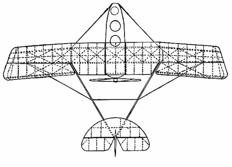
Grahame-White Military Biplane
showing shape and spread of planes and tail, and position of pilot and passenger.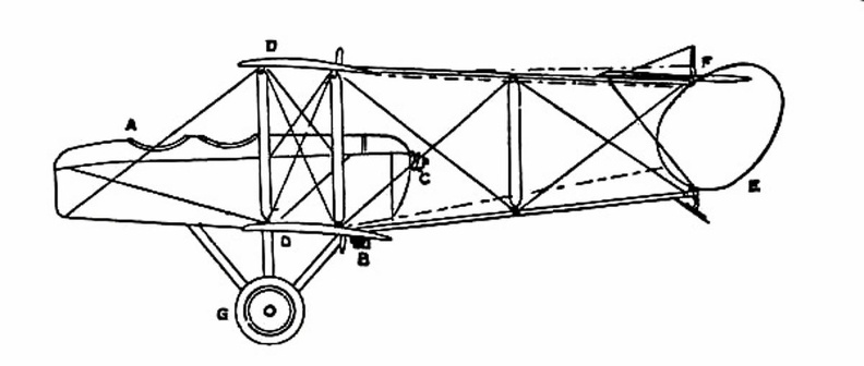
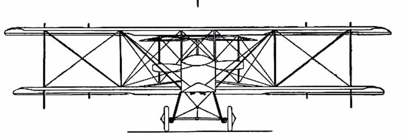
 showing the position of the body and the construction of the landing gear.") Grahame-White Military Biplane - front view
Grahame-White Military Biplane - front view
showing the position of the body and the construction of the landing gear.
 Once the value of aerial reconnaissance had been proved, France proceeded to the development of a sc...") Grahame-White Military Biplane - side view
Grahame-White Military Biplane - side view
Once the value of aerial reconnaissance had been proved, France proceeded to the development of a scouting aeroplane; and the need, in such a machine, is that the observer shall have a clear view ahead and below. The construction of machines was, for this reason, modified. The front elevating plane was moved to the rear, where it was fitted in the form of a flap—as in the case of monoplanes—and the pilot and observer placed in a covered-in body, which projected in front of the main-planes, as shown in the figure. By placing the body before the planes, the observer has a clear view ahead and on either side; and even when he leans over the side, and looks directly downward, there is no surface to obstruct him. A. Covered-in body, with seats for pilot and passenger B. Motor (to minimise wind resistance, only the lower cylinders are exposed to the air) C. Propeller D. Main-planes E. Rudder F. Elevator G. Landing gear.
") Group of French Aviators
Group of French Aviators Grumman OA-9
Front Side
...") Grumman OA-9
Grumman OA-9
Grumman OA-9 Front Side Perspective Bottom Top Henson and Stringfellow built in 1845 a model which weighed about 30 lbs.; and although its stabilit...") Henson and Stringfellow’s Model
Henson and Stringfellow’s Model
Henson and Stringfellow built in 1845 a model which weighed about 30 lbs.; and although its stability was not perfect, it was an interesting machine—a forecast of the monoplane of the future. Here one saw the lifting planes take shape; the body between the wings; the tail-planes at the rear; and, above all, a suggestion of the means by which machines would be driven through the air: the fitting to the model, that is to say, of revolving propellers or screws. When an inventor has fitted an engine to an aircraft, means must be devised for using its power to drive the machine through the air; and to make the wings flap like those of a bird, has been found so complicated, owing to the mechanism necessary to imitate natural movements, that much of the power is wasted. Inventors such as Henson and Stringfellow, realising this difficulty, made wings that were outstretched and immovable, like those of a bird when it is soaring, and relied upon screw propellers—which they set spinning at great speed by means of their engines—to thrust their craft forward through the air. One of the first to work upon Sir George Cayley’s theories was an experimenter
named Henson. H...") Henson's Proposed machine
Henson's Proposed machine
One of the first to work upon Sir George Cayley’s theories was an experimenter named Henson. He planned an ambitious machine weighing about a ton. It was to have planes of canvas stretched over a rigidly trussed frame of bamboo rods and hollow wooden spars; and these planes were to contain 4500 square feet of lifting surface, and be driven by screws operated by a steam engine of 30 h.p. But this craft did not take practical shape, although in its appearance and many of its details it bore a resemblance to machines which ultimately were to fly. In the specification of the patent he took out for his invention, Henson indicated that it was for “Improvements in locomotive apparatus and machinery for conveying letters, goods, and passengers from place to place through the air.” Hull of a Zeppelin during construction.
Craft of the semi-rigid type provide a link between small...") Hull of a Zeppelin during construction
Hull of a Zeppelin during construction
Hull of a Zeppelin during construction. Craft of the semi-rigid type provide a link between small, non-rigid ships and the very large machine which is built with an entirely rigid framework, and has its example in the Zeppelin. The maker forms a skeleton hull of aluminium or some light metal alloy, a method that is shown in figure. The hull of a Zeppelin, slightly more than 500 feet in length, is sheathed with tightly stretched fabric; and within it are the gas-containers—a row of seventeen separate balloons, each in a compartment by itself, and containing a total of nearly 1,000,000 cubic feet of gas—which give these airships a lifting power of close upon 30 tons. Illustration from U.S. patent 385087,
issued to Carl Benz, showing the horizontal plane
of the fly...") Illustration from U.S. patent 385087
Illustration from U.S. patent 385087
Illustration from U.S. patent 385087, issued to Carl Benz, showing the horizontal plane of the flywheel, a feature utilized by the Duryeas in their machine. One of the largest sailing-ships afloat is the French five-master, La France, launched in 1890 on th...") La France
La France
One of the largest sailing-ships afloat is the French five-master, La France, launched in 1890 on the Clyde, and owned by Messrs A. D. Bordes et Fils, who possess a large fleet of sailing-vessels. In 1891 she came from Iquique to Dunkirk in one hundred and five days with 6000 tons of nitrate; yet she was stopped on the Tyne when proceeding to sea with 5500 tons of coal, and compelled to take out 500 tons on the ground that she was overladen.") LA Motordrome
LA Motordrome Lady driving in a horse and cart") Lady driving in a horse and cart
Lady driving in a horse and cart
Lady driving in a horse and cart One of the men who thus laboured, without himself seeing his work brought to the goal of success, wa...") Langley’s Steam-driven Model
Langley’s Steam-driven Model
One of the men who thus laboured, without himself seeing his work brought to the goal of success, was Professor S. P. Langley, an American scientist connected with the Smithsonian Institution, and a man of original ideas and great resource. He made a methodical investigation of the action of lifting planes and the shape of propellers, using a large revolving table so that he could test the latter while they were moving through the air. Then he began building models which took a double monoplane form, as indicated in picture, with wings set at dihedral or upturned angle. This uptilting of the wings was to give the models stability while in flight: and the fixing of planes at the dihedral angle was tested, by later experimenters, in regard to full-sized machines. By another method, shown in figure, the sea-plane is launched from a cable suspended between two mas...") Launching a sea-plane from a wire
Launching a sea-plane from a wire
By another method, shown in figure, the sea-plane is launched from a cable suspended between two masts, and can come to rest upon the cable again after a flight has been made. The machine is hung upon the cable prior to making an ascent; then the pilot starts his engine, and as his machine glides forward along the cable he releases a catch and soars into the air. Upon returning he flies beneath the cable, and makes his craft rise until the “V”-shaped apparatus above his head is caught by the cable and the catch becomes operative; then he stops his motor, and his craft hangs from the cable as it did before. A. Sea-plane B. Cable C. The “V”-shaped apparatus which guides the cable into the clip (D.) and so suspends the machine from the wire. There is a type of aeroplane which will be carried to sea when a fleet sails, stowed in sections wit...") Launching sea-planes from a ship’s deck
Launching sea-planes from a ship’s deck
There is a type of aeroplane which will be carried to sea when a fleet sails, stowed in sections within the hull of a transport ship. This machine—a light, high-speed craft—will be assembled upon the deck of its parent ship, and launched into the air by special mechanism, as there is not room for a machine to run upon wheels, and leave the ship’s deck as it might do upon land; the vessel, besides, might be rolling in a high sea. In some cases a platform is built upon the deck, either at the bow or stern, and along this the aircraft moves, so as to gain speed for its planes to lift. In one device, seen in Figure, the machine is mounted upon a light wheeled cradle, and this is placed upon the starting-rail. Then, driven by its propeller, the plane runs forward upon the cradle till it reaches the end of the rail, when it glides into the air, the cradle falling from it and dropping into the sea, from which it is retrieved and drawn back on board the ship. The sea-plane (A.) is seen taking flight, having glided upon its cradle along the platform (B.). The cradle (C.) is just falling away below the aircraft’s hull. Two assistants took the machine by its plane-ends and ran forward with it, the pilot assuming before...") Launching the Wright Glider
Launching the Wright Glider
Two assistants took the machine by its plane-ends and ran forward with it, the pilot assuming beforehand his position upon the plane; then, when they had gained a pace sufficient for the machine to soar, they released their hold and it glided forward. Beneath the glider, under the centre of the lower plane, there were two wooden skates or runners, and these took the weight of the machine when it alighted, and allowed it to slide forward across the ground before coming to rest. By the use of these landing skids, and by steering at as fine an angle as possible, the Wrights found they could touch ground, even at 20 miles an hour and lying across the machine, without injury either to themselves or the craft. Now, patient and assiduous, he (Lilienthal) began to teach himself the art of aerial balance. Raisin...") Lilienthal gliding
Lilienthal gliding
Now, patient and assiduous, he (Lilienthal) began to teach himself the art of aerial balance. Raising his wings to his shoulders he would face the wind—which in his first tests he did not care to be blowing at more than ten or fifteen miles an hour. Then, running against the wind to increase the pressure beneath his wings, he would raise his legs and begin to glide, moving forward and at the same time downward. How he appeared when in flight is indicated by the picture. Lilienthal was fascinated by the mechanism of the bird’s wing. He and his brother built one machin...") Lilienthal's Experiments
Lilienthal's Experiments
Lilienthal was fascinated by the mechanism of the bird’s wing. He and his brother built one machine after another to determine the exact amount of lifting effort that a man could obtain by imitating the wing-beat of a bird. One such apparatus is illustrated. This had a double set of wings; a wide pair in the centre and narrower ones in front and at the rear. These wings beat alternately, by movements of the operator’s legs; and the machine was suspended by a rope and pulleys from a beam, being counterbalanced by a weight. The tests showed this: that, after some practice in working the wings, a man could raise with them just half the weight of himself and of the machine; but the muscular effort proved so great that he could only maintain this rate of wing-beating for a few seconds. Here, incidentally, a fact may be mentioned: the energy a man can produce, at all events for a prolonged effort, has been estimated at about a quarter of a horse-power; and this—in tests so far made—has been insufficient for the purpose of wing-flapping flight. Lockheed A-29&A
Front Side...") Lockheed A-29&A
Lockheed A-29&A
Lockheed A-29&A Front Side Perspective Bottom Top Lockheed C-40A
Front Side ...") Lockheed C-40A
Lockheed C-40A
Lockheed C-40A Front Side Perspective Bottom Top Lockheed C60-A
Front Side ...") Lockheed C60-A
Lockheed C60-A
Lockheed C60-A Front Side Perspective Bottom Top Lockheed P-38D&E
Front Sid...") Lockheed P-38D&E
Lockheed P-38D&E
Lockheed P-38D&E Front Side Perspective Bottom Top “Looping the loop,” which has made so great a sensation, has taught airmen one definite lesson; ...") Looping the loop
Looping the loop
“Looping the loop,” which has made so great a sensation, has taught airmen one definite lesson; and it is this: no matter how their machines may be beaten and tossed by the wind, they need not fear a fall—provided they are high enough above ground. The movements of a machine, as it makes a series of “loops,” are shown in the figure. The pilot reaches a high speed before he rears up his machine to begin the “loop,” and this downward velocity is attained by diving; then, when he estimates his pace sufficient, he pulls his elevating-lever back and the machine leaps upward, rearing itself vertically towards the sky, turning over on its back, then diving again and coming right-side-up—thus achieving a complete somersault. A skilled trick-flyer, also, will allow his machine to drop sideways or tail first, deliberately working the controls so that it shall do so. Then, just as it seems to spectators that he is falling to destruction, he will dive or twist, regain the mastery of his machine, and descend in a normal glide.