


 When the Wrights had built an engine, there was still the question how they should make it drive the...") Wright Motor and Propellers
Wright Motor and Propellers
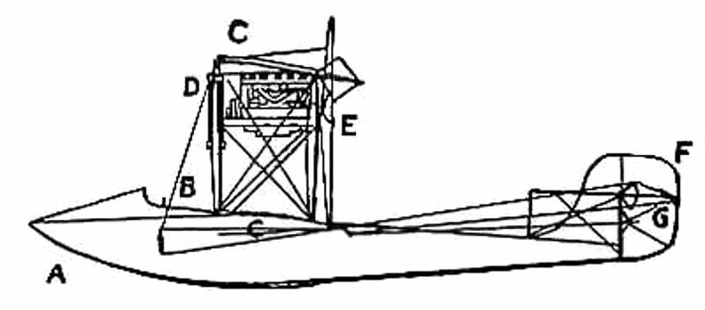
When the Wrights had built an engine, there was still the question how they should make it drive their aeroplane. They inclined naturally to the idea of an aerial propeller. Two courses lay open to them; they could fit one propeller running at high speed and coupled directly to the motor, or they could use two propellers, revolving at slower speed and geared in some way to the engine. They decided upon the latter course, placing two propellers behind the main planes of their machine and driving them from the engine by means of light chains, these running in guiding tubes. This system of propulsion is shown. A. Motor; B. Gear-wheels upon motor crank-shaft; C.C. Tubes carrying driving chains; D.D. Sprocket-wheels over which chains pass; E.E. Propellers. A. Biplane; B. Rail; C. Rope passing from the aeroplane round the pulley-wheel (D.) and thence to th...") Wright Launching Rail
Wright Launching Rail
A. Biplane; B. Rail; C. Rope passing from the aeroplane round the pulley-wheel (D.) and thence to the derrick (E.); (F.) Falling weight. Details of propulsion and control being arranged, there remained the question of how the machine should be launched into the air. In their gliding tests, it will be remembered, the Wrights employed assistants, who held the machine by the wing-tips and ran forward with it. But the weight of the power-driven machine, and its greater size, prevented such a plan as this. They decided, therefore, to launch it from a rail, and to aid its forward speed, at the moment of taking the air, by a derrick and a falling weight.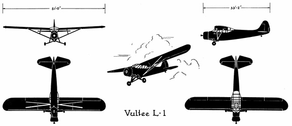 Vultee L-1
Vultee L-1 Front Side Perspective Bottom Top Vultee BT-15
Vultee BT-15 Front Side Perspective Bottom Top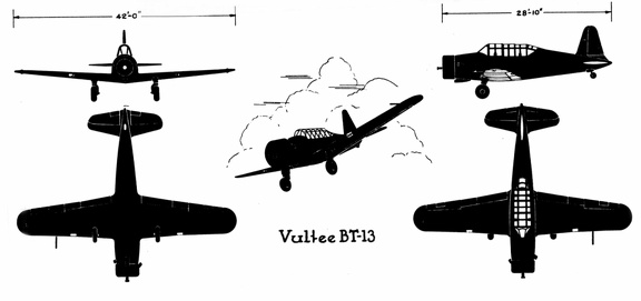 Vultee BT-13
Vultee BT-13 Front Side Perspective Bottom Top Vultee A-31
Front Side
...") Vultee A-31
Vultee A-31
Vultee A-31 Front Side Perspective Bottom Top In the launching of gliders, some French experimenters showed ingenuity. The brothers Voisin, for in...") Voisin Glider towed by a motor-car
Voisin Glider towed by a motor-car
In the launching of gliders, some French experimenters showed ingenuity. The brothers Voisin, for instance, who played a prominent part in the early tests in France, adopted the plan illustrated. The gilder was towed by a motor-car across an open stretch of ground; then, when its speed was sufficient for the planes to lift, it rose and flew behind the car like a kite. A form of glider, mounted upon hollow wooden floats—anticipating the sea-plane of to-day—and tow...") Voisin Glider on the river Seine
Voisin Glider on the river Seine
A form of glider, mounted upon hollow wooden floats—anticipating the sea-plane of to-day—and towed upon the river Seine by a motor-boat. This gilder also, when its speed became sufficient, rose into the air. In the construction of the machine, a biplane, one notes resemblances to the method of the Wrights; and yet generally the craft is dissimilar. There needs to be an equipment of spare machines also; and a number of travelling workshops with ski...") Travelling workshop for the repair of military aeroplanes
Travelling workshop for the repair of military aeroplanes
There needs to be an equipment of spare machines also; and a number of travelling workshops with skilled engineers, which can be rushed from place to place for the repair of damaged craft. A sketch of one of these workshops on wheels, which are vital to the organisation, is seen in the figure Air raid siren in Paris") Tooting the sirens of warning
Tooting the sirens of warning
Air raid siren in Paris British plane flying over the trenches in the great war") They swoop down over the trenches
They swoop down over the trenches
British plane flying over the trenches in the great war Apart from governing the ascending or descending movement, there was the question of preventing a ma...") The Wright Wing-warp
The Wright Wing-warp
Apart from governing the ascending or descending movement, there was the question of preventing a machine from slipping sideways; and this the Wrights solved ingeniously. They saw, of course, that when their glider lurched to one side or the other, they would need some power to tilt it back again. So they devised a system by which the plane-ends of their machine—being made flexible—might be warped, or caused to shift up and down. This action the operator controlled, as he lay across the lower plane, by a movement of cords, and its operation is shown in Figure. The effect upon the machine may be described thus: should a wind-gust tilt down one plane-end, the “warp” upon that side of the machine was drawn down also, and the effect of this—seeing that it caused the plane to assume a steeper angle to the air and exercise a greater lift—was to raise the plane-ends that had been driven down by the gust. By a system of connecting the control cords, this balancing influence was made to act with double force; when one wing warped down, the other moved up; and, in this way, while the side of the machine tilted down was made to rise, the other plane-ends, which had been lifted, were made to descend. A dual righting influence was thus obtained. This system, which imitates the flexing movements made by a bird, was an important device; the Wrights patented it—combining the movement with an action of the rudder—and brought cases at law to enforce their rights. The Wright Brothers Aero Engine") The Wright Brothers Aero Engine
The Wright Brothers Aero Engine
The Wright Brothers Aero Engine A.A.—Main-planes; B. Double front elevator; C. Rudder (two narrow vertical planes); D. Motor; E. P...") The Wright Biplane
The Wright Biplane
A.A.—Main-planes; B. Double front elevator; C. Rudder (two narrow vertical planes); D. Motor; E. Propellers; F. Pilot’s lever; G. Skids upon which machine landed. It is now possible to describe, as a completed craft, the Wright power-driven plane; The picture shows its appearance; and in looking at it one is struck by the fact that, save for one or two modifications, and the fitting of motor and propellers, the machine is practically a glider, such as the Wrights used for soaring tests. Of the changes to be observed, the most interesting concern the elevator and rear-rudder. The former, it will be seen, has a double plane; it is, in fact, a smaller biplane on the principle of the main-planes. Needing to increase the surface of the elevator, the brothers fixed one plane above another so as to make the construction stronger and occupy less space. The rear-rudder, acting like that of a ship. The Voisin Biplane - top view") The Voisin Biplane - top view
The Voisin Biplane - top view
The Voisin Biplane - top view At the beginning of 1909 there were two types of successful aeroplane—the Wright and the Voisin. B...") The Voisin Biplane
The Voisin Biplane
At the beginning of 1909 there were two types of successful aeroplane—the Wright and the Voisin. Bleriot had flown with his monoplane and flown well; but he was still in the process of evolving a practical machine, and several other inventors were in a similar stage. It was the Wright and the Voisin which had proved their worth; and the Wright, as has been said, was the better of the two. Of the Voisin, as flown in 1909, a reproduction is given in the figure. It was a heavier aeroplane than the Wrights’, owing largely to the weight of its alighting gear (250 lbs.) and of its big balancing tail (more than 100 lbs.); hence the necessity for using a 50-h.p. motor, which drove a two-bladed metal propeller at the rate of 1200 revolutions a minute. The Voisin brothers, and other French makers, did not approve of the two-propeller system of the Wrights: they preferred one screw, revolving at high speed. But there was no doubt—at any rate in this stage of aviation—that the Wright method was more efficient than that of the Frenchmen. It was calculated, indeed, that the Wright biplane, when actually in the air, could be driven at an expenditure of only 15 h.p.; whereas the Voisin, even with its 50-h.p. motor running at full speed, had only just enough power to fly. A. Elevating plane B. Pilot’s seat C.C. Main-planes D. Engine and propeller E. Landing chassis F. Balancing tail G. Rudder. Already, anticipating war in the air, a fighting aeroplane has been evolved; and a machine of this t...") The Vickers
The Vickers
Already, anticipating war in the air, a fighting aeroplane has been evolved; and a machine of this type is shown in Figure. The body, in which pilot and gunner sit, is armoured lightly with plates which will resist the penetration of a bullet. Such armouring was found necessary after the use of aeroplanes in Tripoli and the Balkans. When flying unavoidably low in these campaigns, and when fired at from the ground, the wooden bodies of machines were pierced by shot, and in several instances their occupants wounded. A fighting aeroplane A. Machine-gun projecting from opening in bow B. Gunner’s position C. Pilot’s seat D.D. Side windows for observation E. Engine and propeller. A. Enclosed body
B. Driver’s position
C. Steering wheel
D. Foot-controlled throttle lever for e...") The single-seated 'air-car'—a suggested type
The single-seated 'air-car'—a suggested type
A. Enclosed body B. Driver’s position C. Steering wheel D. Foot-controlled throttle lever for engine E.E. The two sustaining-planes F. The motor G. Propeller H. Rudder I. Elevating-plane J. Landing gear. First probably for mails, and after this for passenger-carrying, will aeroplanes of the future be employed; and they will find a scientific use, too, in exploring remote corners of the earth, and in passing above forests which are now impenetrable. Small, fast machines, much cheaper than those of to-day, will be bought also for private use—many of them, as suggested by the figure, having room for only one man within their hulls. Then there will be flying clubs; and to these, after their day’s work, will come a city’s toilers. Through the cheapening of craft, as time goes on, practically all members of the community will experience the joys of flight. Thus, say on a summer’s evening, the doors of the sheds will be pushed aside, and the machines wheeled out and overhauled; then, one by one, these small, fast-moving craft will rise into the air and dart here and there—circling, manœuvring, dipping, and diving. The difficulty with air-cooling—although it had obvious advantages over water-cooling—was to bri...") The seven-cylinder 50-h.p. Gnome motor.
The seven-cylinder 50-h.p. Gnome motor.
The difficulty with air-cooling—although it had obvious advantages over water-cooling—was to bring enough air to play upon the surfaces of the cylinders; and it was here that the Gnome won so complete a success. In other engines the cylinders were stationary, and their pistons, moving up and down in the cylinders, turned a crank-shaft to the end of which the propeller was fixed. Therefore the only air the cylinders obtained was what rushed upon them through the speed of the machine in flight. But in the Gnome, instead of the cylinders remaining stationary and the crank-shaft revolving, the cylinders themselves spun round, and the crank-shaft did not move. An illustration of this motor with one end of the crank-chamber removed, so that the piston-rods can be seen, is given in the figure. It will be noted that there are seven cylinders, set in the form of a star, and that the seven piston-rods projecting from them come together upon a single crank-pin, which is attached to the stationary crank-shaft and turns round it. The propeller, instead of being fitted to the crank-shaft, as was the case with other motors, was bolted to a plate upon the engine itself, so that when this turned around its crank-shaft, it carried the propeller with it. The seaplane shoots off the catapult") The seaplane shoots off the catapult
The seaplane shoots off the catapult
The seaplane shoots off the catapult An experimenter who braved this apathy and won his way until he became a constructor of aircraft, wa...") The Roe Triplane
The Roe Triplane
An experimenter who braved this apathy and won his way until he became a constructor of aircraft, was Mr. A. V. Roe. For some time he was an advocate of the triplane form of machine—a craft, that is to say, with three main-planes fitted one above another. The machine with which he obtained flights, although they were very brief, is seen in the figure. Subsequently, however, Mr. Roe adopted the biplane form. His distinction in the pioneer days was that he managed to make his triplane lift into the air and fly a short distance, with the aid of a motor-cycle engine developing no more than 9 h.p. A.A.A. Three main-planes B. Motor C. Four-bladed propeller D.D.D. Triplane tail E. Rudder F. Landing gear. The engines drove two canvas-covered wooden screws, each 18 feet in length, and the general appearan...") The Maxim Machine
The Maxim Machine
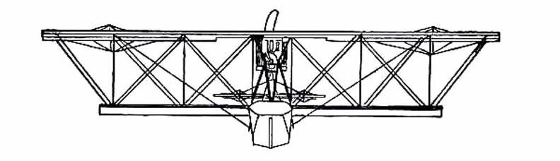
The engines drove two canvas-covered wooden screws, each 18 feet in length, and the general appearance of the machine is indicated by the picture. In these trials, although it was always captive, the aeroplane demonstrated much that its inventor had set himself to prove. In Sir Hiram Maxim’s own words, it showed that it had “a lifting effect of more than a ton, in addition to the weight of three men and 600 lbs. of water.” He adds: “My machine demonstrated one very important fact, and that was that very large aeroplanes had a fair degree of lifting power for their area.” A. Pilot’s seat and controlling wheel
B. Passenger’s seat
C. Movable flap to facilitate enteri...") The hull of a Flying-Boat
The hull of a Flying-Boat
A. Pilot’s seat and controlling wheel B. Passenger’s seat C. Movable flap to facilitate entering the hull D. Handle, like that of a car, for starting the engine E. The engine F. Fuel tanks G. The propeller.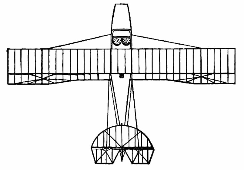
 showing the span of main-planes, elevator, and tail, also the positions of landing gear and pilot’...") The Farman Biplane - top view
The Farman Biplane - top view
showing the span of main-planes, elevator, and tail, also the positions of landing gear and pilot’s seat.
In July, at Rheims, there was to be the great flying meeting; and Farman had made up his mind to...") The Farman Biplane
The Farman Biplane
In July, at Rheims, there was to be the great flying meeting; and Farman had made up his mind to wait for this. Aided by the experience he had gained with the Voisin machine, he had designed a craft which should be generally more efficient and faster in flight, and more quickly responsive to its controls. The biplane he produced, marking as it did a step forward in construction, is a machine that needs description. The general appearance of the craft is indicated by Fig. 46, while an illustration of this type of machine in flight will be found on Plate VII. A feature of the Voisin that Farman discarded was the vertical panel fitted between the main-planes to give sideway stability. An objection to these planes was that they added to the weight of the machine and checked its speed, tending also to drive it from its course should there be a side wind. But in taking away such fixed balancing-planes, Farman had to substitute another device; and what he did was to work upon the same theory as the Wrights had done, and obtain a similar result in a different way. They, it will be remembered, had warped the rear portions of their main-planes. Farman kept his planes rigid, but fitted to their rear extremities four narrow, hinged planes, or flaps, which could be moved up and down and were called ailerons. Their effect was the same as with the Wright wing-warp. When a gust tilted the machine, the pilot drew down the ailerons upon the side that was inclined downward; whereupon the air-pressure, acting upon the drawn-down surfaces, restored the machine to an even keel. A. Elevating-plane; B.B. Main-planes; C. Pilot’s seat; D. Motor and propeller; E. Petrol tank; F.F. Hinged balancing-planes, or ailerons; G.G. Tail-planes; H.H. Twin vertical rudders; I. Landing wheels and skid The depth bomb destroys a U-Boat") The depth bomb destroys a U-Boat
The depth bomb destroys a U-Boat
The depth bomb destroys a U-Boat The Curtiss Biplane making a turn") The Curtiss Biplane making a turn
The Curtiss Biplane making a turn
The Curtiss Biplane making a turn The Curtiss Biplane in flight") The Curtiss Biplane in flight
The Curtiss Biplane in flight
The Curtiss Biplane in flight showing the chassis and the position between the planes of the two ailerons (A.A.).") The Curtiss Biplane front view
The Curtiss Biplane front view
showing the chassis and the position between the planes of the two ailerons (A.A.). Of famous aeroplanes at Rheims, five types stood out by themselves—the Farman, the Voisin, the Wri...") The Curtiss Biplane
The Curtiss Biplane
Of famous aeroplanes at Rheims, five types stood out by themselves—the Farman, the Voisin, the Wright, the Bleriot, and the Antoinette, all of which have been described. But there was one other, which few people had heard of before it appeared here. This was the Curtiss biplane, built by an American named Glenn H. Curtiss, and engined with a motor which also bore his name. Curtiss had experimented with many power-driven machines—motor-cycles, motor-cars, airships, and aeroplanes—and had won a prize in America with a small, light biplane, and it was a craft of this type—as seen in the figure —that he brought with him to Rheims, his idea being to compete for the speed prize. The machine had a front elevator and tail-planes, according to the practice in biplane construction; but an innovation was the setting of the ailerons midway between the main-planes—a position that will be noted in the sketch; another novelty was the way these ailerons operated. At the pilot’s back, as he sat in his driving seat, was an upright rod with two shoulder-pieces—by means of which, should he shift his body, he could swing the rod from side to side. Wires ran from the rod to the ailerons; and if the pilot leaned over, say, to the right, he drew down the ailerons on the left side of the machine. The merit of such a control was that it was instinctive; that is to say, should the biplane tip down on one side, it was natural for the pilot to lean away from the plane-ends that were sinking; and he operated the ailerons automatically, as he did this, and so brought the machine level again. A. Elevating-planes B. Pilot’s seat and control-wheel C.C. Main-planes D. Ailerons E. Motor and propeller F. Tail-plane and rudder. showing the large size of the elevators, the position of the pilot, and the placing of the propeller...") The Cody Biplane from above
The Cody Biplane from above
showing the large size of the elevators, the position of the pilot, and the placing of the propellers. Another ardent worker in England, and one destined to become famous, was Mr. S. F. Cody. After devel...") The Cody Biplane
The Cody Biplane
Another ardent worker in England, and one destined to become famous, was Mr. S. F. Cody. After developing a system of man-lifting kites which the British War Office acquired, he joined the military aircraft factory that had been established at Farnborough. Here, after tests with dirigible balloons, he began the construction of experimental biplanes—all machines of large size. Early in 1909 he made brief flights—the longest being one of about 250 yards. Then, after alterations to his machine, he managed in July to fly a distance of 4 miles. This he increased afterwards to 8 miles; and then on 1st September flew for 1 hour 3 minutes, rising to a height of 300 feet. Cody’s biplane was a very large machine, having 1000 square feet of lifting surface—twice that of the Farman or Voisin. Driving it was an 80-h.p. engine, which operated two propellers on the system used by the Wrights. With its pilot on board the machine weighed 2170 lbs. A. Elevating-planes and vertical-plane B. Pilot’s control lever C.C. Main-planes D. Motor E. Propellers F. Rudder G. Landing gear H. Rear skid. A.A. Ballast bags filled with sand
B. Instruments (such as a statoscope, which shows at any moment ...") The car of a modern Balloon
The car of a modern Balloon
A.A. Ballast bags filled with sand B. Instruments (such as a statoscope, which shows at any moment whether the balloon is rising or falling; and an altitude meter) C. Ring by which car is attached to balloon. The Bleriot Monoplane - top view showing its bird-like shape and the position of the pilot.") The Bleriot Monoplane - top view
The Bleriot Monoplane - top view
The Bleriot Monoplane - top view showing its bird-like shape and the position of the pilot. A. Propeller
B. Motor
C. Sustaining-plane
D. Pilot’s seat
E. Landing chassis
F. Combined tail...") The Bleriot Monoplane
The Bleriot Monoplane
A. Propeller B. Motor C. Sustaining-plane D. Pilot’s seat E. Landing chassis F. Combined tail and elevating-planes G. Rudder. It was on June 5, 1783 that Stephen and Joseph Montgolfier, two French brothers, sent up the first b...") The ascension of Montgolfier’s balloon
The ascension of Montgolfier’s balloon
It was on June 5, 1783 that Stephen and Joseph Montgolfier, two French brothers, sent up the first balloon. You can just imagine the amazement it caused when it arose from the ground. showing the spread of the planes and tail, and the delicate taper of the long, canoe-shaped body.") The Antoinette Monoplane - top view
The Antoinette Monoplane - top view
showing the spread of the planes and tail, and the delicate taper of the long, canoe-shaped body. At the beginning of 1909 a new monoplane made its appearance in France—a powerful, finely construc...") The Antoinette Monoplane
The Antoinette Monoplane
At the beginning of 1909 a new monoplane made its appearance in France—a powerful, finely constructed, and very stable machine. It was the Antoinette, designed by a famous engineer, and it was this craft which interested Latham. M. Levavasseur was the designer of it and of a specially lightened motor, first applied to motor-boats, and afterwards to the experimental biplane of M. Santos-Dumont and also to the aeroplane with which Farman first flew. The Antoinette, which M. Levavasseur also fitted with one of his motors, was a large monoplane—far larger than the Bleriot; and built not with the idea of being a fair-weather machine, but to fly in winds. The span of its wings was 46 feet, and they contained 365 square feet of sustaining surface, while the total weight was 1040 lbs. A. Propeller B. Motor C. Sustaining-plane D. Pilot’s seat and controlling wheel E.E. Vertical rudders F. Elevating-plane G. Landing gear. (649 visits) Their first glider was a biplane, with 165 square feet of lifting surface, as illustrated in figure;...") The 1900 Wright Glider (operator’s position)
The 1900 Wright Glider (operator’s position)
Their first glider was a biplane, with 165 square feet of lifting surface, as illustrated in figure; several of its features need explanation. First there is the position of the operator; he can be seen lying prone across the centre of the lower plane. This attitude was adopted by the Wrights to minimise wind-pressure. Should a man be upright in his machine, they calculated that his body would, as the glider passed through the air, offer an appreciable resistance; while, in lying flat, he would offer scarcely any resistance at all. Stearman PT-17 & 18
Front ...") Stearman PT-17 &18
Stearman PT-17 &18
Stearman PT-17 & 18 Front Side Perspective Bottom Top A machine that has achieved success, owing to its power of varying speed, is the Sopwith military bi...") Sopwith Military Biplane
Sopwith Military Biplane
A machine that has achieved success, owing to its power of varying speed, is the Sopwith military biplane. Adopting a practice that has become general, its wings are fitted upon what is practically a monoplane body. Tail-planes and rudder are the same as in a monoplane. The top main-plane, as will be seen, is set slightly in advance of the lower. The system is called “staggering”; and the idea is that, by placing the upper plane ahead of the lower, the total lifting power will be increased. It has been proved a disadvantage of the biplane that, when the main-planes are placed one above another, there is a slight loss of lift owing to the fact that, acting upon the air as they do quite close to each other, a certain amount of interference occurs between them—one tending to disturb the air-stream in which the other moves. By “staggering” the two planes this interference is overcome; but some makers regard it as a small consideration, and build their planes in the ordinary way, allowing as large a gap as possible between them. In the Sopwith military machine, engine and propeller are in front of the main-planes; then come the places for pilot and observer. The pilot sits first, and the body of the machine is so high that only his head appears above it, while just in front of his face, to deflect the wind-rush from the propeller, there is a raised section of the hull which acts as a screen. Behind the pilot, sitting in a second opening in the hull, is the observer. He has a view forward, rendered the better by setting back the lower-plane; while at the point at which it joins the body of the machine, immediately below him, this plane is hollowed out, so that he can look directly upon the earth below. Small windows are also fitted upon either side of the hull. Through those in front the pilot may glance when descending from a flight, so as to judge his distance from the ground, while the others are utilised by the observer, as he turns to look from side to side. This biplane, and many others, is balanced against sideway roll by ailerons, and not by warping the wings. Constant warping, such as is necessary in the everyday use of machines, has been declared to strain a plane and render it weak; therefore the use of ailerons is now favoured. A. Propeller B. Motor, partly hidden by shield C.C. Main-planes D. Pilot’s seat E. Observer’s seat F. Outlook windows in side of hull G. Rudder H. Elevating-plane I. Landing gear. Some types of American and foreign aeroplanes") Some types of American and foreign aeroplanes
Some types of American and foreign aeroplanes
Some types of American and foreign aeroplanes Some types of American and foreign aeroplanes") Some types of American and foreign aeroplanes
Some types of American and foreign aeroplanes
Some types of American and foreign aeroplanes Hence there is a type of fast scouting monoplane, in which a pilot can ascend alone, and fly at 100 ...") Single-seated Air Scout
Single-seated Air Scout
Hence there is a type of fast scouting monoplane, in which a pilot can ascend alone, and fly at 100 miles an hour. With such a craft, sweeping rapidly above an enemy’s position, the pilot-observer can return with his information at surprising speed. In the figure an air-scout of this type is seen. The tapering, covered-in body will be observed; this is to reduce wind resistance as the machine rushes through the air. The Gnome engine is, for the same reason, covered by an aluminium shield, which only allows the lower cylinders to project; they must, of course, be exposed in some way to the air, or they would not cool themselves. The landing-carriage has been reduced to its simplest form; this, again, is to reduce wind resistance; and the pilot, sitting deep in the body, shows only his head as the machine flies. Here, again, apart from the greater comfort in being so shielded, the placing of the pilot within the machine spells a lessening of pressure. A. Propeller B. Motor (partly hidden by shield) C. Pilot’s seat D. Sustaining plane E. Rudder F. Elevating-plane G. Chassis. Shop engine, 1901") Shop engine, 1901
Shop engine, 1901
Shop engine, 1901 Ship saved by life line thrown from a rescue airship
[Not sure what it did to save the boat]") Ship saved by life line thrown from a rescue airship
Ship saved by life line thrown from a rescue airship
Ship saved by life line thrown from a rescue airship [Not sure what it did to save the boat] But as airships were built larger, and greater speeds were obtained, it became necessary to strength...") Semi-rigid Airship
Semi-rigid Airship
But as airships were built larger, and greater speeds were obtained, it became necessary to strengthen the envelopes with some form of keel; and this led to a type which is known as the semi-rigid, and is developed successfully in France. The figure illustrates an airship of this build. Along the lower side of its envelope is placed a light, rigid framework or keel, and from this is suspended the car which contains engines and crew. A. Gas-containing envelope B. Strengthening keel C.C. Stabilising-planes D. Rudder E. Car carrying engines, propeller, and crew. A coastal sea-plane, as now planned, is a craft having, say, two engines, each devolving 120 h.p., w...") Sea-plane to carry a crew of seven
Sea-plane to carry a crew of seven
A coastal sea-plane, as now planned, is a craft having, say, two engines, each devolving 120 h.p., with a wing span of some 80 feet, and an accommodation in its hull for three men—the pilot, a combatant with a machine-gun, and an observer with an installation of wireless. But types are changing constantly, and the tendency is to build larger craft. A machine weighing a couple of tons is shown, and a novelty in regard to it is that it has wheels upon either side of its boat-shaped car, upon which it can move on land, and which fold upward when it rests upon the water. A. Hull upon which the machine floats when in the sea B.B.B. Wheels upon which it may move when on land, and which fold upward when it is on the water C. Pilot’s controlling wheel D.D. Main sustaining planes E. Four-bladed propeller driven by chain-gearing from engine within the hull. (1403 visits) Scouting over the ruined region between the lines (no man’s land)") Scouting over the ruined region between the lines (no man’s land)
Scouting over the ruined region between the lines (no man’s land)
Scouting over the ruined region between the lines (no man’s land) To meet the demand for a purely scouting machine, in which pilot and passenger shall have a clear fi...") Scouting Monoplane, with occupants below the wings.
Scouting Monoplane, with occupants below the wings.
To meet the demand for a purely scouting machine, in which pilot and passenger shall have a clear field for observation, both above and below, a monoplane has been designed which is called the “parasol.” This machine, a Morane-Saulnier, is shown. The two sustaining wings, forming a single surface, are raised above the body so that its occupants have nothing to impede their view earthward; and they can also see above them—an advantage of course in time of war, seeing that an enemy might be hovering overhead A. Engine and propeller B. Plane raised above hull C. Seats for pilot and passenger D. Rudder E. Elevating-plane. It was not until 1906, at a time when the Wright aeroplane was capable of long flights, that a real ...") Santos-Dumont’s Biplane which flew at Bagetelle
Santos-Dumont’s Biplane which flew at Bagetelle
It was not until 1906, at a time when the Wright aeroplane was capable of long flights, that a real French success was obtained; and then the flights made were brief, and carried out with a craft that was admittedly crude. It was a biplane of curious construction, built by the Voisin brothers for M. Santos-Dumont—a rich Brazilian who had spent money freely upon airships, and had been occupied, for some time before the Voisins made him this machine, with a craft having propellers to lift it vertically from the ground. Abandoning this idea, he devoted himself to the machine the Voisins built, which is seen in the picture. When petrol engines became available, they gave an impetus to the building of airships; for, like th...") Santos-Dumont’s Airship
Santos-Dumont’s Airship
When petrol engines became available, they gave an impetus to the building of airships; for, like the aeroplane, the airship needed a motive agent which gives a high power for a low weight. One of the first to use a petrol motor in an airship with success was M. Santos-Dumont, whose name has been mentioned in connection with aeroplanes. He tested small, light airships, driven by petrol engines and two-bladed propellers—as illustrated in figure; and with one of these, on a calm, still day, he flew over Paris and round the Eiffel Tower. A. Gas envelope B. Wheeled framework which carried motor, propeller, and pilot’s seat C. Elevating-plane D. Horizontal rear-plane E. Rudder. Ryan PT-22
Front Side
...") Ryan PT-22
Ryan PT-22
Ryan PT-22 Front Side Perspective Bottom Top Republic P43-A
Front Side ...") Republic P43-A
Republic P43-A
Republic P43-A Front Side Perspective Bottom Top Republic P-47B
Front Side ...") Republic P-47B
Republic P-47B
Republic P-47B Front Side Perspective Bottom Top Republic P-35
Front Side
...") Republic P-35
Republic P-35
Republic P-35 Front Side Perspective Bottom Top Republic AT-12
Front Side ...") Republic AT-12
Republic AT-12
Republic AT-12 Front Side Perspective Bottom Top Plane going down in flames") Plane going down in flames
Plane going down in flames
Plane going down in flames Pilot and passenger") Pilot and passenger
Pilot and passenger
Pilot and passenger Phillips built the strange-looking machine. It resembled, more than anything else, a huge Venetian b...") Phillips’s Experimental Craft
Phillips’s Experimental Craft
Phillips built the strange-looking machine. It resembled, more than anything else, a huge Venetian blind; and he adopted this form so as to introduce as many narrow planes as possible. There were, as a matter of fact, fifty in the machine, each 22 feet long and only 1½ inch wide. The craft, as can be seen, was mounted on a light carriage which, having wheels fitted to it, ran round and round upon a railed track. A steam engine was used as motive power, driving a two-bladed propeller at the rate of 400 revolutions a minute. The machine was so arranged on its metals that, although the rear wheels could raise themselves and show whether the planes exercised a lift, the front one was fixed to its track—thus preventing the apparatus from leaping into the air, overturning, and perhaps wrecking itself. Tests with the machine were successful. The lifting influence of the planes, when the engine drove them forward, was sufficient to raise the rear wheels from the track; and they did so even when a weight of 72 lbs., in addition to that of the apparatus, had been placed upon the carriage. In his main object, then, Phillips succeeded; and that was to show the lifting power of his planes. But his apparatus had not the makings of a practical aeroplane. He gained for himself, nevertheless, a name that has lived and will live.