


 A \"No. 2 flying boat,\" just built by Mr. Curtiss, and successfully tested on Lake Keuka, Hammondspor...") Diagram of the Curtiss Flying Boat no. 2
Diagram of the Curtiss Flying Boat no. 2
A "No. 2 flying boat," just built by Mr. Curtiss, and successfully tested on Lake Keuka, Hammondsport, in July, 1912, is the "last word" in aviation so far. An illustration in this book, made from photographs taken in mid-July, 1912, shows fully the bullet-shape of the "flying fish." It is a real boat, built with a fish-shaped body containing two comfortable seats for the pilot and passenger or observer, either of whom can operate the machine by a system of dual control, making it also available for teaching the art of flying. All the controls are fastened to the rear of the boat's hull, which makes them very rigid and strong, while the boat itself, made in stream-line form, offers the least possible resistance to the air, even less than that offered by the landing gear upon a standard land machine. Above the boat are mounted the wings and aeroplane surface. In the centre of this standard biplane construction is situated the eighty horse-power motor with its propeller in the rear, thus returning to the original practice, as in the standard Curtiss machines, of having a single propeller attached direct to the motor, thus doing away with all chains and transmission gearing which might give trouble, and differing from the earlier model flying boat built in San Diego, California, last winter (1911-12), which was equipped with "tractor" propellors propellers in front driven by chains. The new flying boat is twenty-six feet long and three feet wide. The planes are five and a half feet deep and thirty feet wide. It runs on the water at a speed of fifty miles an hour, and is driven by an eighty horse-power Curtiss motor. At a greater speed than this it cannot be kept on the water, but rises in the air and flies at from fifty to sixty miles per hour. Douglas A-20B & C
Front Si...") Douglas A-20B & C
Douglas A-20B & C
Douglas A-20B & C Front Side Perspective Bottom Top Douglas A-24
Front Side
...") Douglas A-24
Douglas A-24
Douglas A-24 Front Side Perspective Bottom Top Douglas B-18
Front Side
...") Douglas B-18
Douglas B-18
Douglas B-18 Front Side Perspective Bottom Top Douglas B-18A
Front Side
...") Douglas B-18A
Douglas B-18A
Douglas B-18A Front Side Perspective Bottom Top Douglas B-23
Front Side
...") Douglas B-23
Douglas B-23
Douglas B-23 Front Side Perspective Bottom Top Douglas C-39
Front Side
...") Douglas C-39
Douglas C-39
Douglas C-39 Front Side Perspective Bottom Top Douglas C-47
Front Side
...") Douglas C-47
Douglas C-47
Douglas C-47 Front Side Perspective Bottom Top Douglas C-54A
Front Side
...") Douglas C-54A
Douglas C-54A
Douglas C-54A Front Side Perspective Bottom Top Douglas O-46A
Front Side
...") Douglas O-46A
Douglas O-46A
Douglas O-46A Front Side Perspective Bottom Top Douglas XB-19
Front Side
...") Douglas XB-19
Douglas XB-19
Douglas XB-19 Front Side Perspective Bottom Top In the picture the operator is seen in the driving seat; and near him will be observed the motor whi...") Driving seat of Wright Biplane
Driving seat of Wright Biplane
In the picture the operator is seen in the driving seat; and near him will be observed the motor which drives the craft. In his left hand—that is to say in the one nearest us—he grasps the lever which operates the elevating planes. The rod from lever to plane can be seen, and the motions the pilot makes are these: should he wish to rise, he draws the lever towards him and tilts up the elevating planes in the manner already described, increasing the lifting power of the main-planes and so causing the machine to ascend; by a reverse movement of the lever—by pushing it away from him, that is to say—he makes the craft glide downward.") Driving-seat of a touring plane
Driving-seat of a touring plane Dropping off in parachute from flaming balloon") Dropping off in parachute from flaming balloon
Dropping off in parachute from flaming balloon
Dropping off in parachute from flaming balloon Another machine which is stable in flight, owing to the peculiar formation of its wings, which resis...") Dunne inherently stable Biplane
Dunne inherently stable Biplane
Another machine which is stable in flight, owing to the peculiar formation of its wings, which resist a diving or plunging movement, or a lateral swing, is the Dunne biplane—as designed by Lieutenant J. W. Dunne. This craft is seen in the figure. Using such a machine, pilots have flown for long distances with the control levers locked, the biplane adapting itself automatically to the wind-gusts and preserving its equilibrium without aid of any kind. It has neither fore-plane nor tail; it is made to ascend by elevators which are in the form of hinged flaps, or ailerons, and is steered by two rudders at the extremities of the main-planes. A. Hull containing pilot and passenger B.B. Main-planes C.C.C.C. Flaps used as elevators D.D. Side-planes which act as rudders E. Engine and propeller F. Alighting gear. Giffard was succeeded in France, first by Dupuy de Lome; then by Gaston Tissandier, well-meaning pro...") Dupuy de Lome’s dirigible, 1872
Dupuy de Lome’s dirigible, 1872
Giffard was succeeded in France, first by Dupuy de Lome; then by Gaston Tissandier, well-meaning projectors of steerable balloons, but too cautious to effect an important advance in the art. The first of these gentlemen, an eminent marine engineer, in 1872, completed a gas balloon for the French government, resembling the one designed by General Meusnier in 1784, and like that also driven by muscular power actuating a screw, and kept rigidly inflated by use of an internal balloon, or ballonet. The car was suspended from the bag by a close fitting cover instead of a net, in order to lessen the resistance, and it was kept in alignment by use of crossed suspension cords. A speed of but six miles an hour was attained by the industrious work of eight men operating an ample screw propeller. A decade later Tissandier, with a balloon of like design, but driven by the power of an electric motor and bichromate of potash battery, attained a speed of six to eight miles an hour. A typical craft, representing the first of those navigated with any certainty, is shown in Figure. A...") Early-type Airship
Early-type Airship
A typical craft, representing the first of those navigated with any certainty, is shown in Figure. A gas-containing envelope, made of a light, strong, varnished fabric, is kept taut by the pressure of the gas within; the car, constructed of wood or metal tubing, is suspended by ropes from the envelope, and contains engine and crew, with a two-bladed propeller revolving astern. Such a machine, in its control, had an elevating-plane and rudder, upon the same principle as those of the aeroplane. One of the difficulties to be overcome was the expansion and contraction of gas in the envelope owing to differences in altitude and temperature. When the craft ascended, its envelope completely inflated, the gas began to dilate owing to the outer air becoming less dense; and some had to be allowed to escape through automatic valves. Then, should the machine descend to a lower level, there was not sufficient gas in the envelope to keep it tightly stretched, and it tended to sag at the bow as it was driven through the air. A. Gas envelope B. Car suspended below envelope C. Motor, which drives propeller (D) through a shaft E. Small horizontal plane for rising or descending F. Fixed fin, or keel plane, to give stability G. Rudder. Fairchild PT-19
Front Side...") Fairchild PT-19
Fairchild PT-19
Fairchild PT-19 Front Side Perspective Bottom Top Fast mail-carrying aeroplanes will make postal deliveries everywhere") Fast mail-carrying aeroplanes will make postal deliveries everywhere
Fast mail-carrying aeroplanes will make postal deliveries everywhere
Fast mail-carrying aeroplanes will make postal deliveries everywhere Fighting Zeppelin raiders") Fighting Zeppelin raiders
Fighting Zeppelin raiders
Fighting Zeppelin raiders Of the doings of another of these brave but reckless men—a Saracen who tried to fly in the twelfth...") First attempts
First attempts
Of the doings of another of these brave but reckless men—a Saracen who tried to fly in the twelfth century—there is fuller information. He provided himself with wings which he stiffened with wooden rods, and held out upon either side of his body. Wearing these, he mounted to the top of a tower in Constantinople and stood waiting for a favourable gust of wind. When this came and caught his wings, he “rose into the air like a bird.” And then, of course, seeing that he had no idea of balancing himself when actually aloft, he fell pell-mell and “broke his bones.” People who had gathered to watch, seeing this inglorious ending to the flight, burst into laughter: ridicule rather than praise, indeed, was the fate of the pioneers, even to the days when the first real flights were made. First flight engine, 1903") First flight engine, 1903
First flight engine, 1903
First flight engine, 1903 First flight engine, 1903 rear view") First flight engine, 1903 rear view
First flight engine, 1903 rear view
First flight engine, 1903 rear view First flight engine, 1903, assembly") First flight engine, 1903, assembly
First flight engine, 1903, assembly
First flight engine, 1903, assembly First flight engine, 1903, cross section") First flight engine, 1903, cross section
First flight engine, 1903, cross section
First flight engine, 1903, cross section A still more ambitious helicopter was that shown invented by Professor Forlanini, an Italian Civil E...") Forlanini’s helicopter, 1878
Forlanini’s helicopter, 1878
A still more ambitious helicopter was that shown invented by Professor Forlanini, an Italian Civil Engineer, and launched in 1878. The lower screw was fastened to the frame of a steam engine, the upper screw was attached to the crank shaft. Steam was supplied from the globe shown beneath, which was two thirds filled with water, and well heated over a separate fire just before an ascension. As the globe was merely a reservoir of hot water and steam, carrying neither fuel nor furnace, its power waned rapidly. The best flight lasted about twenty seconds, attaining a height of 42 feet. The apparatus weighed 77 pounds, spread 21.5 square feet of screw surface, and lifted about 26.4 pounds per horse power. “In the accompanying figure the solid arrows in the interior part represent the resultant motions ...") General circulation of the atmosphere
General circulation of the atmosphere
“In the accompanying figure the solid arrows in the interior part represent the resultant motions of the winds (longer arrows indicating greater velocities), in case of an earth with a homogeneous surface over both hemispheres, in which the motions would be symmetrical in both and the same at all longitudes, and the equatorial and tropical calm belts would be situated at equal distances from each pole. The dotted arrows indicate the strong, almost eastern motion of the air at all latitudes at some high altitude, as that of the cirrus clouds. While Blanchard and other aëronauts were paddling their globose bags in search of favorable winds, ...") General Meusnier’s proposed dirigible, 1784
General Meusnier’s proposed dirigible, 1784
While Blanchard and other aëronauts were paddling their globose bags in search of favorable winds, vainly hoping thereby to direct their course in the air, General Meusnier of the French army, and member of the Academy of Sciences, made a systematic study of the requirements for practical air navigation. After some research on forms suitable for aëronautic hulls, he designed a power balloon having a pointed car suspended from a bag of goose-egg form, this latter embodying his idea of the best shape for a balloon that must cleave the air swiftly and resist deformation. The propulsion was to be effected by means of three coaxial screw propellers, supported on the rigging between car and bag, and actuated by eighty men, for lack of a light artificial motor. He thus hoped to obtain a moderate velocity which, combined with skillfully selected air currents, would enable the ship to reach her destination in ordinary weather The illustrious Henri Giffard was perhaps the first aëronautical engineer adequately endowed and ci...") Giffard’s steam dirigible, 1852
Giffard’s steam dirigible, 1852
The illustrious Henri Giffard was perhaps the first aëronautical engineer adequately endowed and circumstanced to realize, on a practical scale, General Meusnier’s well pondered and truly scientific plans for a motor balloon. He had studied in the college of Bourbon, and had worked in the railroad shops of the Paris and St. Germain railway. He had further equipped himself by making free balloon ascensions, under the auspices of Eugene Godard, for the purpose of studying the atmosphere; and by building light engines, one of which weighed 100 pounds, and developed three horse power. Finally in 1851 he patented an air ship, consisting of an elongated bag and car, propelled by a screw driven by a steam engine. He had not the means to build such a vessel, but he had the genius and training necessary to construct it, and at the same time enough enthusiasm and persuasive power to induce his friends, David and Sciama, to loan him the requisite funds. Parseval Kite Balloon.
Another valiant English leader in aërostation was James Glaisher, member ...") Glaisher and Coxwell
Glaisher and Coxwell
Parseval Kite Balloon. Another valiant English leader in aërostation was James Glaisher, member of the British Association for the Advancement of Science. As one of a committee of twelve appointed by that body in 1861, to explore the higher strata of the atmosphere by means of the balloon, he volunteered his services as an observer, when no other capable man could offer to do so. With a professional aëronaut, Mr. Coxwell, and a new balloon specially constructed for the work, cubing 90,000 feet, he made eleven ascensions for the society, four from Wolverhampton, seven from Woolwich. Incidentally he made seventeen other ascents of various altitude; not at the expense of the committee, but as a scientific passenger in public balloon ascents advertised beforehand. showing shape and spread of planes and tail, and position of pilot and passenger.") Grahame-White Military Biplane
Grahame-White Military Biplane
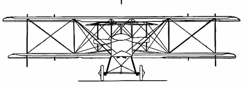
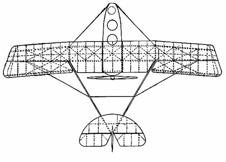
showing shape and spread of planes and tail, and position of pilot and passenger.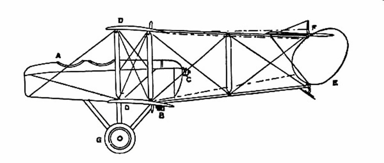
 showing the position of the body and the construction of the landing gear.") Grahame-White Military Biplane - front view
Grahame-White Military Biplane - front view
showing the position of the body and the construction of the landing gear.
 Once the value of aerial reconnaissance had been proved, France proceeded to the development of a sc...") Grahame-White Military Biplane - side view
Grahame-White Military Biplane - side view
Once the value of aerial reconnaissance had been proved, France proceeded to the development of a scouting aeroplane; and the need, in such a machine, is that the observer shall have a clear view ahead and below. The construction of machines was, for this reason, modified. The front elevating plane was moved to the rear, where it was fitted in the form of a flap—as in the case of monoplanes—and the pilot and observer placed in a covered-in body, which projected in front of the main-planes, as shown in the figure. By placing the body before the planes, the observer has a clear view ahead and on either side; and even when he leans over the side, and looks directly downward, there is no surface to obstruct him. A. Covered-in body, with seats for pilot and passenger B. Motor (to minimise wind resistance, only the lower cylinders are exposed to the air) C. Propeller D. Main-planes E. Rudder F. Elevator G. Landing gear.
 The Gross III measured 70 meters long, cubed 7,500 meters, and was propelled by four Körting motors...") Gross III
Gross III
The Gross III measured 70 meters long, cubed 7,500 meters, and was propelled by four Körting motors aggregating 300 horse power. This was a splendid vessel, and one of extraordinary speed.") Group of French Aviators
Group of French Aviators Grumman OA-9
Front Side
...") Grumman OA-9
Grumman OA-9
Grumman OA-9 Front Side Perspective Bottom Top One interesting outcome of his numerous experiments was the Hargrave Kite, now more familiarly known...") Hargrave’s kite
Hargrave’s kite
One interesting outcome of his numerous experiments was the Hargrave Kite, now more familiarly known as the box kite. A good example of his kites is the type shown. This consists of two arched biplanes mounted tandem on a backbone, or connecting framework. The kite floats steadily, and was thought suitable for the body of a flying machine to be driven by an engine and propeller. Thus meteorology is indebted to aëronautics for its most useful kite. In 1891, twelve years after Tatin’s experiment, Lawrence Hargrave, of Sydney, Australia, made a si...") Hargrave’s model screw monoplane, 1891
Hargrave’s model screw monoplane, 1891
In 1891, twelve years after Tatin’s experiment, Lawrence Hargrave, of Sydney, Australia, made a similar compressed air monoplane, with a single-screw propeller, but without wheels for launching and lighting. The model, which is shown, had a wing-spread of 20 square feet, weighed about three pounds, and flew 128 feet in eight seconds. The weight carried was at the rate of 90 pounds per horse power, a very encouraging result. Two years later he described a small steam engine which he had developed, weighing 10.7 pounds per horse power, and capable of driving the model about two miles, though he did not use it for that purpose, being engrossed with other researches. Henson and Stringfellow built in 1845 a model which weighed about 30 lbs.; and although its stabilit...") Henson and Stringfellow’s Model
Henson and Stringfellow’s Model
Henson and Stringfellow built in 1845 a model which weighed about 30 lbs.; and although its stability was not perfect, it was an interesting machine—a forecast of the monoplane of the future. Here one saw the lifting planes take shape; the body between the wings; the tail-planes at the rear; and, above all, a suggestion of the means by which machines would be driven through the air: the fitting to the model, that is to say, of revolving propellers or screws. When an inventor has fitted an engine to an aircraft, means must be devised for using its power to drive the machine through the air; and to make the wings flap like those of a bird, has been found so complicated, owing to the mechanism necessary to imitate natural movements, that much of the power is wasted. Inventors such as Henson and Stringfellow, realising this difficulty, made wings that were outstretched and immovable, like those of a bird when it is soaring, and relied upon screw propellers—which they set spinning at great speed by means of their engines—to thrust their craft forward through the air. One of the first to work upon Sir George Cayley’s theories was an experimenter
named Henson. H...") Henson's Proposed machine
Henson's Proposed machine
One of the first to work upon Sir George Cayley’s theories was an experimenter named Henson. He planned an ambitious machine weighing about a ton. It was to have planes of canvas stretched over a rigidly trussed frame of bamboo rods and hollow wooden spars; and these planes were to contain 4500 square feet of lifting surface, and be driven by screws operated by a steam engine of 30 h.p. But this craft did not take practical shape, although in its appearance and many of its details it bore a resemblance to machines which ultimately were to fly. In the specification of the patent he took out for his invention, Henson indicated that it was for “Improvements in locomotive apparatus and machinery for conveying letters, goods, and passengers from place to place through the air.” Hull of a Zeppelin during construction.
Craft of the semi-rigid type provide a link between small...") Hull of a Zeppelin during construction
Hull of a Zeppelin during construction
Hull of a Zeppelin during construction. Craft of the semi-rigid type provide a link between small, non-rigid ships and the very large machine which is built with an entirely rigid framework, and has its example in the Zeppelin. The maker forms a skeleton hull of aluminium or some light metal alloy, a method that is shown in figure. The hull of a Zeppelin, slightly more than 500 feet in length, is sheathed with tightly stretched fabric; and within it are the gas-containers—a row of seventeen separate balloons, each in a compartment by itself, and containing a total of nearly 1,000,000 cubic feet of gas—which give these airships a lifting power of close upon 30 tons. In 1850 a clockmaker and skillful workman, Jullien by name, exhibited in the Hippodrome, at Paris, a...") Jullien’s model dirigible, 1850
Jullien’s model dirigible, 1850
In 1850 a clockmaker and skillful workman, Jullien by name, exhibited in the Hippodrome, at Paris, a torpedo-shaped model balloon of gold-beater’s skin, provided with a screw propeller at either side of its bow, and a double rudder at its stern. It measured 23 feet in length and weighed 1,100 grammes complete. The propellers were actuated by spring power, and proved able to drive the tiny vessel against a moderate wind. The most suitable form for the bag was determined by towing models through water. The largest hot-air balloon ever constructed, La Flesselle, was launched from the suburbs of the cit...") La Flesselle
La Flesselle
The largest hot-air balloon ever constructed, La Flesselle, was launched from the suburbs of the city of Lyons on January 19, 1784, just two months after the ascent of the first human passengers. It was also one of the most troublesome to assemble and keep in repair. Day by day, for more than a week, the balloon was inflated for the purpose of attaching the ropes to support the great gallery. But the wind blew dreadfully at times; rain and snow fell on the machine; frost and ice covered the huge bag; many rents ensued, demanding frequent repairs. On one occasion, when fed too freely with flame from straw sprinkled with alcohol, the monstrous ship rose so vigorously as to drag fifty men with it some distance along the ground. Finally on the 19th of January, when the weather moderated, the operators built small fires under the scaffold below the balloon, and thawed away the ice from the drenched and frozen bag. Then they stocked its gallery with straw and pitchforks, with fire extinguishers, and other provisions for the journey. The inflation beginning about noon, occupied but seventeen minutes. The balloon swelled out rapidly, with the roaring flames ascending inside, and at last stood forth huge and majestic before the admiring multitude—a towering thing of magic growth, 100 feet in diameter by 130 feet high. The Ville de Paris showed considerable resemblance to her prototype, the France of 1884, but differe...") La Ville de Paris
La Ville de Paris
The Ville de Paris showed considerable resemblance to her prototype, the France of 1884, but differed from that elegant vessel in various important features. Her hull was shaped like a wine bottle with its thickest end, or bow, brought to a sharp projectile point, and its other end furnished, like an arrow, with four fixed guiding surfaces to steady its flight. These guiding surfaces were elongated, finlike, cylindrical sacs, inflated as shown in the illustration. The hull measured 200 feet long, 34½ feet in major diameter, 112,847 cubic feet in volume. Heavy bands of canvas with their edges sewed along the sides of the balloon served as flaps for the attachment of the cords suspending the long car beneath. With this long suspension the weight of the car was more evenly distributed over the envelope than in the Lebaudy balloons. An interesting improvement in this air ship was the stabilizing planes, placed above the car, fore and aft, to lift or depress aëroplanelike, thus enabling the pilot to raise or lower the vessel, also to alter her trim, or to check her pitching. As might be expected, her flight was very steady, but as the motor developed only 70 to 75 horse power, her velocity did not exceed twenty-five miles per hour. In January, 1908, she made a run of 147 miles in seven hours, six minutes, with an average speed of 21 miles an hour. The first vacuum balloon was proposed by the Jesuit father, Francis Lana, and described in his book ...") Lana’s proposed vacuum balloon
Lana’s proposed vacuum balloon
The first vacuum balloon was proposed by the Jesuit father, Francis Lana, and described in his book Podromo dell’Arte Maestra Brecia, which appeared in 1670. Though not a practical project like Gusmao’s, it was very ingenious, and marks an interesting phase in the evolution of the fundamental idea of the air ship, or “balloon” as it was called by the inventor, who then coined the word now in common use. Lana proposed to use four copper spheres each 25 feet in diameter and 1/225 inches in wall thickness, quite well exhausted of air, to give ascensional force which he computed at 1,200 pounds aggregate for the four spheres. From these he would suspend the passengers in a boat having a mast and sail to propel the ship in time of favorable wind. Having computed the buoyancy according to well-known physical laws, he could see no possible objection to his project “unless,” he writes, “it be that God would never permit this invention to be practically applied, in order to prevent the consequences that would ensue therefrom in the civil and political government of men.” One of the men who thus laboured, without himself seeing his work brought to the goal of success, wa...") Langley’s Steam-driven Model
Langley’s Steam-driven Model
One of the men who thus laboured, without himself seeing his work brought to the goal of success, was Professor S. P. Langley, an American scientist connected with the Smithsonian Institution, and a man of original ideas and great resource. He made a methodical investigation of the action of lifting planes and the shape of propellers, using a large revolving table so that he could test the latter while they were moving through the air. Then he began building models which took a double monoplane form, as indicated in picture, with wings set at dihedral or upturned angle. This uptilting of the wings was to give the models stability while in flight: and the fixing of planes at the dihedral angle was tested, by later experimenters, in regard to full-sized machines. By another method, shown in figure, the sea-plane is launched from a cable suspended between two mas...") Launching a sea-plane from a wire
Launching a sea-plane from a wire
By another method, shown in figure, the sea-plane is launched from a cable suspended between two masts, and can come to rest upon the cable again after a flight has been made. The machine is hung upon the cable prior to making an ascent; then the pilot starts his engine, and as his machine glides forward along the cable he releases a catch and soars into the air. Upon returning he flies beneath the cable, and makes his craft rise until the “V”-shaped apparatus above his head is caught by the cable and the catch becomes operative; then he stops his motor, and his craft hangs from the cable as it did before. A. Sea-plane B. Cable C. The “V”-shaped apparatus which guides the cable into the clip (D.) and so suspends the machine from the wire. There is a type of aeroplane which will be carried to sea when a fleet sails, stowed in sections wit...") Launching sea-planes from a ship’s deck
Launching sea-planes from a ship’s deck
There is a type of aeroplane which will be carried to sea when a fleet sails, stowed in sections within the hull of a transport ship. This machine—a light, high-speed craft—will be assembled upon the deck of its parent ship, and launched into the air by special mechanism, as there is not room for a machine to run upon wheels, and leave the ship’s deck as it might do upon land; the vessel, besides, might be rolling in a high sea. In some cases a platform is built upon the deck, either at the bow or stern, and along this the aircraft moves, so as to gain speed for its planes to lift. In one device, seen in Figure, the machine is mounted upon a light wheeled cradle, and this is placed upon the starting-rail. Then, driven by its propeller, the plane runs forward upon the cradle till it reaches the end of the rail, when it glides into the air, the cradle falling from it and dropping into the sea, from which it is retrieved and drawn back on board the ship. The sea-plane (A.) is seen taking flight, having glided upon its cradle along the platform (B.). The cradle (C.) is just falling away below the aircraft’s hull. Two assistants took the machine by its plane-ends and ran forward with it, the pilot assuming before...") Launching the Wright Glider
Launching the Wright Glider
Two assistants took the machine by its plane-ends and ran forward with it, the pilot assuming beforehand his position upon the plane; then, when they had gained a pace sufficient for the machine to soar, they released their hold and it glided forward. Beneath the glider, under the centre of the lower plane, there were two wooden skates or runners, and these took the weight of the machine when it alighted, and allowed it to slide forward across the ground before coming to rest. By the use of these landing skids, and by steering at as fine an angle as possible, the Wrights found they could touch ground, even at 20 miles an hour and lying across the machine, without injury either to themselves or the craft. In 1784 Launoy and Bienvenu, the first a naturalist, the second a mechanician, exhibited before the ...") Launoy and Bienvenu’s helicopter, 1784
Launoy and Bienvenu’s helicopter, 1784
In 1784 Launoy and Bienvenu, the first a naturalist, the second a mechanician, exhibited before the French Academy the interesting toy shown. This was the first power-driven helicopter, and is said to have lifted itself in the air quite readily. As may be observed it consists of two coaxial screws rotating in opposite directions actuated by the power of an elastic stick, like a bow. The screws were each about one foot in diameter and made of four feathers; one screw being fastened to the top of the rotating shaft, the other fastened to the bow, which rotated in the contrary direction. The little model excited much interest, particularly as its inventors expected to build a man-carrying helicopter on the same plan. The larger project was obviously without merit; for no combination of springs can maintain flight for more than a few seconds even on the most favorable scale. n experienced sailor, Captain Le Bris, having observed the albatross soaring without wing-beat, dete...") Le Bris’ aëroplane, 1855
Le Bris’ aëroplane, 1855
n experienced sailor, Captain Le Bris, having observed the albatross soaring without wing-beat, determined to imitate the fascinating flight of that limber-winged spirit of the sea. To such end he built the bird shown, a ninety-pound albatross, with arched wings fifty feet across and articulated to the boat-like body. In this the brave aviator would stand upright, turn the wings and tail to maintain his balance, and steer grandly through the sky. Placing this long-winged creature across a cart driven by a peasant, he stood erect and headed against a breeze; the wings set low to prevent lifting till an opportune moment, and the bird held down to the car by a rope which the captain could quickly release. When the horse was a-trot, and the wind blowing freshly, Le Bris raised the front edges of the wings. Besides the great auto balloons designed by Julliot and Surcouf, of which the République and Colone...") Le Petit Journal, Zodiac type
Le Petit Journal, Zodiac type
Besides the great auto balloons designed by Julliot and Surcouf, of which the République and Colonel Renard are examples, a number of convenient cruisers were brought forth in 1909 by the Zodiac Company. One of the leading spirits in this enterprise was the famous Count de la Vaulx, well known for his auto balloon designs and his long voyages in sphericles. The chief merit of these modest air ships, which ranged in volume from 25,000 cubic feet upwards, was cheapness and facility of demounting and shipment. They were intended to popularize the art among the masses, by giving everyone a chance to make a voyage at no great expense. Besides their applicability to sport, touring, and public uses, some were designed for considerable speed and endurance; which qualities, together with their demountability and partial independence of hangars, were expected to give them military value. Previous to Lenormand’s experiments, Blanchard, the aëronaut, had dropped small parachutes from h...") Lenormand’s parachute, 1784
Lenormand’s parachute, 1784
Previous to Lenormand’s experiments, Blanchard, the aëronaut, had dropped small parachutes from his balloon, sometimes carrying animals, but never a human being. For unaccountable reasons the world had to wait fourteen years longer to see a man make the new familiar parachute descent from a balloon. On October 22, 1797, in presence of a large crowd Jacques Garnerin ascended in a closed parachute to a height of 3,000 feet, then cut loose. The people were astonished and appalled; but they soon saw the umbrella-shaped canvas spread open and oscillate in the sky with its human freight. As it was but eight yards in diameter, it descended rapidly and struck the ground with violence, throwing Garnerin from his seat. He escaped with a bruised foot, mounted a horse, and returned to the starting point, where he received a lively ovation. Leonardo da Vinci, the great Italian artist and scientist, who lived in the fifteenth century, spent...") Leonardo da Vinci's Glider and Parachute Idea
Leonardo da Vinci's Glider and Parachute Idea
Leonardo da Vinci, the great Italian artist and scientist, who lived in the fifteenth century, spent years experimenting with the idea of flying. He made a number of sketches of wings to be fitted to the arms and legs of man. His plan for a parachute was soundly worked out and his idea that the wings of a flying machine should be patterned after the wings of the bat found expression in the doped fabric covering of our early airplanes. Now, patient and assiduous, he (Lilienthal) began to teach himself the art of aerial balance. Raisin...") Lilienthal gliding
Lilienthal gliding
Now, patient and assiduous, he (Lilienthal) began to teach himself the art of aerial balance. Raising his wings to his shoulders he would face the wind—which in his first tests he did not care to be blowing at more than ten or fifteen miles an hour. Then, running against the wind to increase the pressure beneath his wings, he would raise his legs and begin to glide, moving forward and at the same time downward. How he appeared when in flight is indicated by the picture. Lilienthal was fascinated by the mechanism of the bird’s wing. He and his brother built one machin...") Lilienthal's Experiments
Lilienthal's Experiments
Lilienthal was fascinated by the mechanism of the bird’s wing. He and his brother built one machine after another to determine the exact amount of lifting effort that a man could obtain by imitating the wing-beat of a bird. One such apparatus is illustrated. This had a double set of wings; a wide pair in the centre and narrower ones in front and at the rear. These wings beat alternately, by movements of the operator’s legs; and the machine was suspended by a rope and pulleys from a beam, being counterbalanced by a weight. The tests showed this: that, after some practice in working the wings, a man could raise with them just half the weight of himself and of the machine; but the muscular effort proved so great that he could only maintain this rate of wing-beating for a few seconds. Here, incidentally, a fact may be mentioned: the energy a man can produce, at all events for a prolonged effort, has been estimated at about a quarter of a horse-power; and this—in tests so far made—has been insufficient for the purpose of wing-flapping flight. Lockheed A-29&A
Front Side...") Lockheed A-29&A
Lockheed A-29&A
Lockheed A-29&A Front Side Perspective Bottom Top Lockheed C-40A
Front Side ...") Lockheed C-40A
Lockheed C-40A
Lockheed C-40A Front Side Perspective Bottom Top Lockheed C60-A
Front Side ...") Lockheed C60-A
Lockheed C60-A
Lockheed C60-A Front Side Perspective Bottom Top Lockheed P-38D&E
Front Sid...") Lockheed P-38D&E
Lockheed P-38D&E
Lockheed P-38D&E Front Side Perspective Bottom Top