


 When the Wrights had built an engine, there was still the question how they should make it drive the...") Wright Motor and Propellers
Wright Motor and Propellers
When the Wrights had built an engine, there was still the question how they should make it drive their aeroplane. They inclined naturally to the idea of an aerial propeller. Two courses lay open to them; they could fit one propeller running at high speed and coupled directly to the motor, or they could use two propellers, revolving at slower speed and geared in some way to the engine. They decided upon the latter course, placing two propellers behind the main planes of their machine and driving them from the engine by means of light chains, these running in guiding tubes. This system of propulsion is shown. A. Motor; B. Gear-wheels upon motor crank-shaft; C.C. Tubes carrying driving chains; D.D. Sprocket-wheels over which chains pass; E.E. Propellers. A. Biplane; B. Rail; C. Rope passing from the aeroplane round the pulley-wheel (D.) and thence to th...") Wright Launching Rail
Wright Launching Rail
A. Biplane; B. Rail; C. Rope passing from the aeroplane round the pulley-wheel (D.) and thence to the derrick (E.); (F.) Falling weight. Details of propulsion and control being arranged, there remained the question of how the machine should be launched into the air. In their gliding tests, it will be remembered, the Wrights employed assistants, who held the machine by the wing-tips and ran forward with it. But the weight of the power-driven machine, and its greater size, prevented such a plan as this. They decided, therefore, to launch it from a rail, and to aid its forward speed, at the moment of taking the air, by a derrick and a falling weight. They found that a slight curve or camber in the wing section would cause the moving air to travel fa...") Wright Brothers' Wind tunnel
Wright Brothers' Wind tunnel
They found that a slight curve or camber in the wing section would cause the moving air to travel farther over the top of the wing surface than along the under side. This made the air pressure greater under the wing, gave a suction effect above the wing, and caused it to rise, creating lift. They discovered that a wing section of the proper camber would counteract the weight of gravity. Thus, a wing must be so designed that, with a certain amount of air flowing around it, it would lift a certain weight. They also discovered that air flow against any surface attached to the wing would cause a resistance or drag. Hundreds of experiments in their wind tunnel with various types of wing shapes gave the Wrights a series of tables from which to design a wing that would create the lift for a designed weight. Out in Dayton, Ohio, there were two small brothers, who dreamed, as countless other children before ...") Wright Brothers' Bicycle shop
Wright Brothers' Bicycle shop
Out in Dayton, Ohio, there were two small brothers, who dreamed, as countless other children before them had dreamed, of flying like birds through the air. Their dreams were heightened by a small toy given to them by their father, the pastor of a local church. This toy was to lead to an idea which had a profound effect on the world. You would probably call it a flying propeller. It consisted of a wooden propeller which slipped over a notched stick. By placing a finger against the propeller and rapidly pushing it up the notched stick, the propeller was made to whirl up off the end of the stick and fly into the air. The brothers, young as they were, never quite forgot this little toy as they continued to dream of flying like birds through the air. Though the brothers continued to dream of flying, they were not the kind of lads who spent all their time in dreaming. They made kites which flew a little better and a little higher than those made by the other boys in the neighborhood. They built a press to print their own little newspaper, and they dabbled in woodcuts. To carve out porch posts for their father’s home they built an eight-foot wood-turning lathe. Indeed, they were the sort of boys who caused the neighbors to say, “What will they think of next?” The brothers knew that if they ever wanted to see their dreams come true they must earn their own capital. In the early nineties America was in the midst of the bicycle craze. Everyone who could possibly afford to do so owned a bicycle of some sort and belonged to a cycle club. Being mechanically minded, the brothers did the logical thing. They set themselves up in a small bicycle shop in Dayton, next door to their home. The bicycle shop in Dayton prospered, for the brothers were careful and expert mechanics, and cyclists in need of repairs made their way to the Wright Brothers’ shop. By 1903 the Wright Brothers were ready to build a powered man-carrying flying machine. Their experim...") Wright Brothers first powered airplane
Wright Brothers first powered airplane
By 1903 the Wright Brothers were ready to build a powered man-carrying flying machine. Their experiments had shown them just how much moving air was necessary to create lift in such a machine. To create the needed thrust, an engine having eight horsepower and weighing not over 200 pounds had to be fitted into the machine. Such an engine was not available, so the Wrights built one in their shop at Dayton, Ohio. They were ready to ship their airplane to Kitty Hawk, N. C., in the fall of 1903. The Wright Brothers were not only inspired mechanics (as many people still believe today) but seriou...") Wright Brotherrs wind tunnel
Wright Brotherrs wind tunnel
The Wright Brothers were not only inspired mechanics (as many people still believe today) but serious scientists, working along the soundest lines. In their keen desire to know what air pressure on wings really was, they cleared a corner of their bicycle shop and built a small wind tunnel with spare lumber and an old electric fan. They built small wing sections of various shapes and experimented with them in their wind tunnel. The electric fan was used to create the moving air around the wing section. By attaching the wing sections to a supporting frame and connecting the frame with a pointer and dial, they were able to keep a record of the effect of moving air on each experimental wing section. Through their wind tunnel research the Wright Brothers discovered the four forces that control all heavier-than-air flight: lift, thrust, weight, and drag. In 1866, two decades after the flight of Stringfellow’s monoplane, Mr. F. H. Wenham, another Engli...") Wenham’s aëroplane, 1866
Wenham’s aëroplane, 1866
In 1866, two decades after the flight of Stringfellow’s monoplane, Mr. F. H. Wenham, another Englishman illustrious in the annals of aëronautics, patented the multiplane; that is, an aëroplane comprising two or more superposed surfaces. This proved to be a valuable contribution to the art of aviation, and continues in use at the present time. The device furnished an increase of sustaining surface without enlargement of the ground plan. It moreover lends itself conveniently to a strong and simple trussing of the surfaces. Some designers protest that superposed surfaces blanket one another; but the advantages just named seem amply to compensate for this objectionable feature. If the surfaces be properly spaced, very little interference is found; moreover, any blanketing that may occur diminishes the drift as well as the lift,[20] though not necessarily in the same proportion. Wenham’s aëroplane is illustrated. The rider lies underneath the multiple wings, so as to diminish the resistance to progression through the air. The apparatus could thus be used as an aërial toboggan for coasting down the atmosphere. To prolong the flights two flappers actuated by a treadle were to be employed, their ends being hinged at a point above the operator’s back. Though the device was patented, no very serious efforts were made to operate it practically. Once, indeed, the inventor took his glider to a meadow and mounted it, during a lull in the evening wind, but soon a gust caught him up, carried him some distance from the ground and toppled him over sidewise, breaking some of the surfaces. The machine disclosed some good working principles; but it was inadequately ruddered, and too feebly constructed, to weather the buffets of the prevailing ground currents.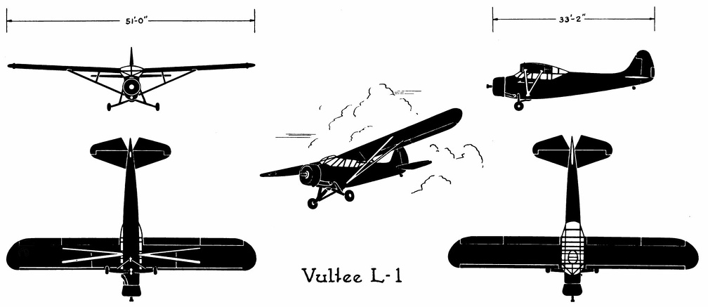 Vultee L-1
Vultee L-1 Front Side Perspective Bottom Top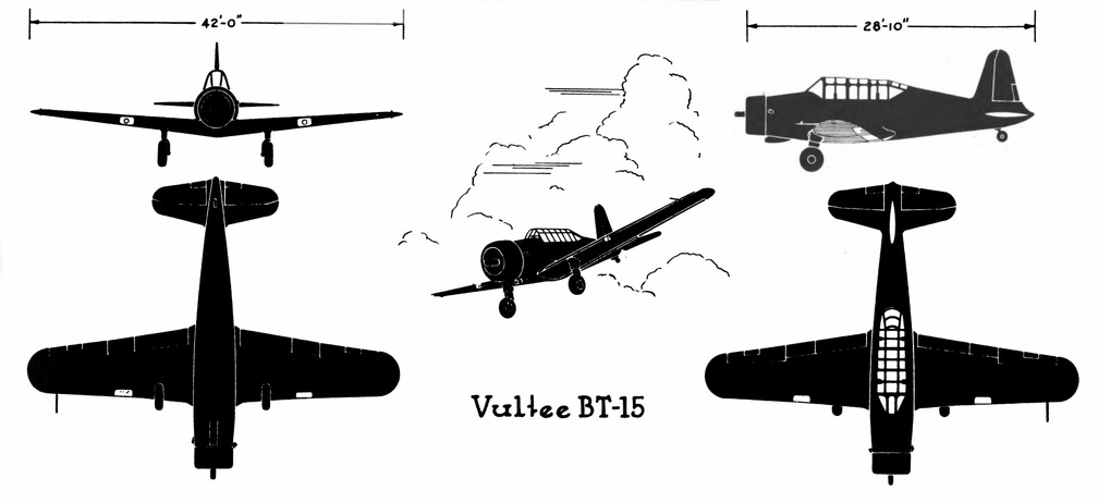 Vultee BT-15
Vultee BT-15 Front Side Perspective Bottom Top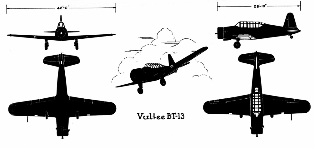 Vultee BT-13
Vultee BT-13 Front Side Perspective Bottom Top Vultee A-31
Front Side
...") Vultee A-31
Vultee A-31
Vultee A-31 Front Side Perspective Bottom Top In the launching of gliders, some French experimenters showed ingenuity. The brothers Voisin, for in...") Voisin Glider towed by a motor-car
Voisin Glider towed by a motor-car
In the launching of gliders, some French experimenters showed ingenuity. The brothers Voisin, for instance, who played a prominent part in the early tests in France, adopted the plan illustrated. The gilder was towed by a motor-car across an open stretch of ground; then, when its speed was sufficient for the planes to lift, it rose and flew behind the car like a kite. A form of glider, mounted upon hollow wooden floats—anticipating the sea-plane of to-day—and tow...") Voisin Glider on the river Seine
Voisin Glider on the river Seine
A form of glider, mounted upon hollow wooden floats—anticipating the sea-plane of to-day—and towed upon the river Seine by a motor-boat. This gilder also, when its speed became sufficient, rose into the air. In the construction of the machine, a biplane, one notes resemblances to the method of the Wrights; and yet generally the craft is dissimilar. The earliest of Da Vinci’s aëronautic ideas to be practically realized was the parachute. The exa...") Veranzio’s parachute
Veranzio’s parachute
The earliest of Da Vinci’s aëronautic ideas to be practically realized was the parachute. The exact date of its first employment is not exactly known. In the year 1617 Fauste Veranzio published in Venice a good technical description of the construction and operation of the parachute, accompanied by a clear illustration. the figure shows the recording anemometer for speed and double direction constructed by the writer i...") Universal anemograph
Universal anemograph
the figure shows the recording anemometer for speed and double direction constructed by the writer in 1892. A large weather vane was firmly strapped to a vertical pipe which turned freely on ball bearings and, by means of a small crank actuating a chronograph pencil, recorded its fluctuations on a long sheet of paper winding on the drum from a roll behind. On top of the pipe and about fifteen feet from the ground, was mounted a carefully balanced horizontal vane, from which a fine steel wire ran down the axis of the pipe to a fixed pulley, thence to a second recording pencil. A third pencil recorded the beats of a pendulum, thus standardizing the speed of the paper. A fourth pencil, not shown, was designed to record the turns of an anemometer mounted near the top of the pipe. The records of the wind speed thus secured are omitted for lack of standardization, as the experiments were prematurely terminated. There needs to be an equipment of spare machines also; and a number of travelling workshops with ski...") Travelling workshop for the repair of military aeroplanes
Travelling workshop for the repair of military aeroplanes
There needs to be an equipment of spare machines also; and a number of travelling workshops with skilled engineers, which can be rushed from place to place for the repair of damaged craft. A sketch of one of these workshops on wheels, which are vital to the organisation, is seen in the figure Air raid siren in Paris") Tooting the sirens of warning
Tooting the sirens of warning
Air raid siren in Paris British plane flying over the trenches in the great war") They swoop down over the trenches
They swoop down over the trenches
British plane flying over the trenches in the great war Apart from governing the ascending or descending movement, there was the question of preventing a ma...") The Wright Wing-warp
The Wright Wing-warp
Apart from governing the ascending or descending movement, there was the question of preventing a machine from slipping sideways; and this the Wrights solved ingeniously. They saw, of course, that when their glider lurched to one side or the other, they would need some power to tilt it back again. So they devised a system by which the plane-ends of their machine—being made flexible—might be warped, or caused to shift up and down. This action the operator controlled, as he lay across the lower plane, by a movement of cords, and its operation is shown in Figure. The effect upon the machine may be described thus: should a wind-gust tilt down one plane-end, the “warp” upon that side of the machine was drawn down also, and the effect of this—seeing that it caused the plane to assume a steeper angle to the air and exercise a greater lift—was to raise the plane-ends that had been driven down by the gust. By a system of connecting the control cords, this balancing influence was made to act with double force; when one wing warped down, the other moved up; and, in this way, while the side of the machine tilted down was made to rise, the other plane-ends, which had been lifted, were made to descend. A dual righting influence was thus obtained. This system, which imitates the flexing movements made by a bird, was an important device; the Wrights patented it—combining the movement with an action of the rudder—and brought cases at law to enforce their rights. After a year of exhaustive study and experiments with models in their wind tunnel, the Wright Brothe...") The Wright Brothers experimental glider
The Wright Brothers experimental glider
After a year of exhaustive study and experiments with models in their wind tunnel, the Wright Brothers were ready to experiment with a man-carrying glider. With the thoroughness that was typical of every move of the Wrights, the brothers asked the government to let them have information on meteorological conditions all over the country. By studying the weather charts they were able to find a locality where there was a continual flow of wind. This would be nature’s wind tunnel where they could test their glider day after day. Through their study of the charts they found that the wind conditions at Kitty Hawk, on the North Carolina coast, seemed to offer the best possibilities for their glider test. Orville and Wilbur Wright began their experiments with a small man-carrying glider at Kitty Hawk in 1900. From that time until 1903 they made hundreds of successful glider flights and kept accurate records of each flight. They recorded wind velocity, angle of flight, duration of flight, time of day, temperature, humidity, and sky conditions overhead with the typical Wright attention to detail. Each year the Wrights constructed new gliders which embodied principles they had discovered for themselves during their flights at Kitty Hawk. Each glider was larger and had longer and narrower wings than the one before. During the fall of 1902 the brothers recorded nearly a thousand flights in a glider with a wingspan of thirty-two feet. It had a front elevator and a vertical tail which helped to maintain lateral stability. The Wright Brothers Aero Engine") The Wright Brothers Aero Engine
The Wright Brothers Aero Engine
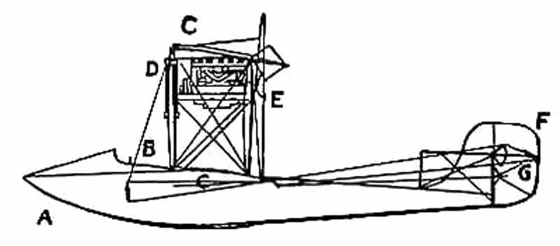
The Wright Brothers Aero Engine A.A.—Main-planes; B. Double front elevator; C. Rudder (two narrow vertical planes); D. Motor; E. P...") The Wright Biplane
The Wright Biplane
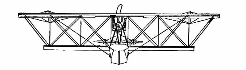
A.A.—Main-planes; B. Double front elevator; C. Rudder (two narrow vertical planes); D. Motor; E. Propellers; F. Pilot’s lever; G. Skids upon which machine landed. It is now possible to describe, as a completed craft, the Wright power-driven plane; The picture shows its appearance; and in looking at it one is struck by the fact that, save for one or two modifications, and the fitting of motor and propellers, the machine is practically a glider, such as the Wrights used for soaring tests. Of the changes to be observed, the most interesting concern the elevator and rear-rudder. The former, it will be seen, has a double plane; it is, in fact, a smaller biplane on the principle of the main-planes. Needing to increase the surface of the elevator, the brothers fixed one plane above another so as to make the construction stronger and occupy less space. The rear-rudder, acting like that of a ship. The Voisin Biplane - top view") The Voisin Biplane - top view
The Voisin Biplane - top view
The Voisin Biplane - top view At the beginning of 1909 there were two types of successful aeroplane—the Wright and the Voisin. B...") The Voisin Biplane
The Voisin Biplane
At the beginning of 1909 there were two types of successful aeroplane—the Wright and the Voisin. Bleriot had flown with his monoplane and flown well; but he was still in the process of evolving a practical machine, and several other inventors were in a similar stage. It was the Wright and the Voisin which had proved their worth; and the Wright, as has been said, was the better of the two. Of the Voisin, as flown in 1909, a reproduction is given in the figure. It was a heavier aeroplane than the Wrights’, owing largely to the weight of its alighting gear (250 lbs.) and of its big balancing tail (more than 100 lbs.); hence the necessity for using a 50-h.p. motor, which drove a two-bladed metal propeller at the rate of 1200 revolutions a minute. The Voisin brothers, and other French makers, did not approve of the two-propeller system of the Wrights: they preferred one screw, revolving at high speed. But there was no doubt—at any rate in this stage of aviation—that the Wright method was more efficient than that of the Frenchmen. It was calculated, indeed, that the Wright biplane, when actually in the air, could be driven at an expenditure of only 15 h.p.; whereas the Voisin, even with its 50-h.p. motor running at full speed, had only just enough power to fly. A. Elevating plane B. Pilot’s seat C.C. Main-planes D. Engine and propeller E. Landing chassis F. Balancing tail G. Rudder. Already, anticipating war in the air, a fighting aeroplane has been evolved; and a machine of this t...") The Vickers
The Vickers
Already, anticipating war in the air, a fighting aeroplane has been evolved; and a machine of this type is shown in Figure. The body, in which pilot and gunner sit, is armoured lightly with plates which will resist the penetration of a bullet. Such armouring was found necessary after the use of aeroplanes in Tripoli and the Balkans. When flying unavoidably low in these campaigns, and when fired at from the ground, the wooden bodies of machines were pierced by shot, and in several instances their occupants wounded. A fighting aeroplane A. Machine-gun projecting from opening in bow B. Gunner’s position C. Pilot’s seat D.D. Side windows for observation E. Engine and propeller. A. Enclosed body
B. Driver’s position
C. Steering wheel
D. Foot-controlled throttle lever for e...") The single-seated 'air-car'—a suggested type
The single-seated 'air-car'—a suggested type
A. Enclosed body B. Driver’s position C. Steering wheel D. Foot-controlled throttle lever for engine E.E. The two sustaining-planes F. The motor G. Propeller H. Rudder I. Elevating-plane J. Landing gear. First probably for mails, and after this for passenger-carrying, will aeroplanes of the future be employed; and they will find a scientific use, too, in exploring remote corners of the earth, and in passing above forests which are now impenetrable. Small, fast machines, much cheaper than those of to-day, will be bought also for private use—many of them, as suggested by the figure, having room for only one man within their hulls. Then there will be flying clubs; and to these, after their day’s work, will come a city’s toilers. Through the cheapening of craft, as time goes on, practically all members of the community will experience the joys of flight. Thus, say on a summer’s evening, the doors of the sheds will be pushed aside, and the machines wheeled out and overhauled; then, one by one, these small, fast-moving craft will rise into the air and dart here and there—circling, manœuvring, dipping, and diving. The difficulty with air-cooling—although it had obvious advantages over water-cooling—was to bri...") The seven-cylinder 50-h.p. Gnome motor.
The seven-cylinder 50-h.p. Gnome motor.
The difficulty with air-cooling—although it had obvious advantages over water-cooling—was to bring enough air to play upon the surfaces of the cylinders; and it was here that the Gnome won so complete a success. In other engines the cylinders were stationary, and their pistons, moving up and down in the cylinders, turned a crank-shaft to the end of which the propeller was fixed. Therefore the only air the cylinders obtained was what rushed upon them through the speed of the machine in flight. But in the Gnome, instead of the cylinders remaining stationary and the crank-shaft revolving, the cylinders themselves spun round, and the crank-shaft did not move. An illustration of this motor with one end of the crank-chamber removed, so that the piston-rods can be seen, is given in the figure. It will be noted that there are seven cylinders, set in the form of a star, and that the seven piston-rods projecting from them come together upon a single crank-pin, which is attached to the stationary crank-shaft and turns round it. The propeller, instead of being fitted to the crank-shaft, as was the case with other motors, was bolted to a plate upon the engine itself, so that when this turned around its crank-shaft, it carried the propeller with it. The seaplane shoots off the catapult") The seaplane shoots off the catapult
The seaplane shoots off the catapult
The seaplane shoots off the catapult An experimenter who braved this apathy and won his way until he became a constructor of aircraft, wa...") The Roe Triplane
The Roe Triplane
An experimenter who braved this apathy and won his way until he became a constructor of aircraft, was Mr. A. V. Roe. For some time he was an advocate of the triplane form of machine—a craft, that is to say, with three main-planes fitted one above another. The machine with which he obtained flights, although they were very brief, is seen in the figure. Subsequently, however, Mr. Roe adopted the biplane form. His distinction in the pioneer days was that he managed to make his triplane lift into the air and fly a short distance, with the aid of a motor-cycle engine developing no more than 9 h.p. A.A.A. Three main-planes B. Motor C. Four-bladed propeller D.D.D. Triplane tail E. Rudder F. Landing gear. The engines drove two canvas-covered wooden screws, each 18 feet in length, and the general appearan...") The Maxim Machine
The Maxim Machine
The engines drove two canvas-covered wooden screws, each 18 feet in length, and the general appearance of the machine is indicated by the picture. In these trials, although it was always captive, the aeroplane demonstrated much that its inventor had set himself to prove. In Sir Hiram Maxim’s own words, it showed that it had “a lifting effect of more than a ton, in addition to the weight of three men and 600 lbs. of water.” He adds: “My machine demonstrated one very important fact, and that was that very large aeroplanes had a fair degree of lifting power for their area.” A. Pilot’s seat and controlling wheel
B. Passenger’s seat
C. Movable flap to facilitate enteri...") The hull of a Flying-Boat
The hull of a Flying-Boat
A. Pilot’s seat and controlling wheel B. Passenger’s seat C. Movable flap to facilitate entering the hull D. Handle, like that of a car, for starting the engine E. The engine F. Fuel tanks G. The propeller.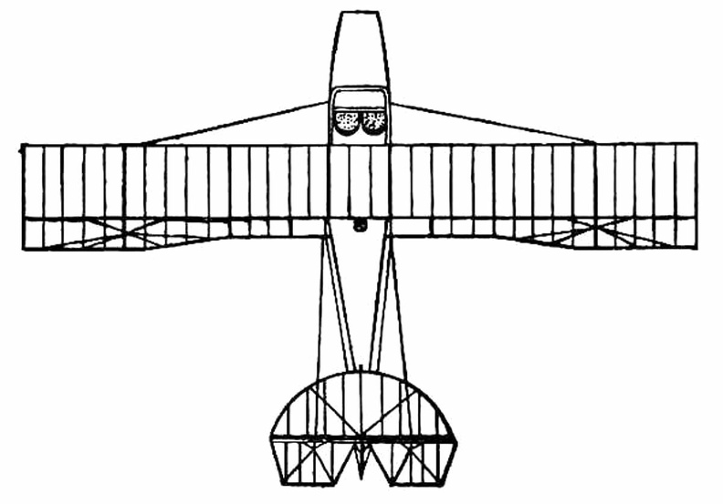
 he vessel selected for that famous cruise was The Great Balloon of Nassau, then recently built by Mr...") The Great Balloon of Nassau
The Great Balloon of Nassau
he vessel selected for that famous cruise was The Great Balloon of Nassau, then recently built by Mr. Green and representing all that his skill and experience could devise. It was of pear shape, formed of the finest crimson and white silk, “spun, wove and dyed expressly for the purpose,” and comprising when distended a volume of 85,000 cubic feet. From its stout balloon-ring six feet in diameter was suspended a wicker car measuring nine feet long by four wide, having a seat across either end, and a cushioned bottom to serve as a bed, if such should be needed. Across the middle of the car was a plank supporting a windlass for raising or lowering the guide-rope, that is a heavy rope which could be trailed over land, or water, to keep the balloon at a nearly constant level without expenditure of ballast, and to check its speed on landing. This valuable device invented by Mr. Green in 1820, was now to receive adequate trial, which, indeed, formed one of the chief purposes of the cruise. Other paraphernalia of the voyage were food and drink, warm clothing, lamps, trumpets, telescopes, barometers, a quicklime coffee-heater, a grapnel and cable, and a ton of sand ballast in bags. after testing more than 200 wing designs and plane surfaces in their wind tunnel, the Wright Brother...") The Four forces of flight
The Four forces of flight
after testing more than 200 wing designs and plane surfaces in their wind tunnel, the Wright Brothers found out how to figure correctly the amount of curve, or camber, that was essential to weight-carrying wings. They discovered, too, that before man could be flown through the air, he must have his wings attached firmly to a body or platform which was firm and controllable. The Wrights in their earliest experiments had realized that to be practical their machine must be built not only to fly in a straight line, but also in order that it could be steered to the right or to the left. One day, Orville was twisting a cardboard box in his hand when Wilbur noticed it. Immediately he saw the solution to the problem of steering their airplane. The result was a design which changed the lift of either end of the wing by warping its surface. If one end of the wing was warped to give it more lift, the machine would lift on that side and fall off into a turn. Thus the problem of steering was solved by the Wrights Historians have unearthed stories in cuneiform writing of man’s attempts to fly. Some of these ins...") The flight of Etana
The flight of Etana
Historians have unearthed stories in cuneiform writing of man’s attempts to fly. Some of these inscriptions date back more than five thousand years, to 3500 B.C. Perhaps the most famous of these stories is the ancient Babylonian tale of the shepherd boy, Etana, who rode on the back of an eagle. showing the span of main-planes, elevator, and tail, also the positions of landing gear and pilot’...") The Farman Biplane - top view
The Farman Biplane - top view
showing the span of main-planes, elevator, and tail, also the positions of landing gear and pilot’s seat.
In July, at Rheims, there was to be the great flying meeting; and Farman had made up his mind to...") The Farman Biplane
The Farman Biplane
In July, at Rheims, there was to be the great flying meeting; and Farman had made up his mind to wait for this. Aided by the experience he had gained with the Voisin machine, he had designed a craft which should be generally more efficient and faster in flight, and more quickly responsive to its controls. The biplane he produced, marking as it did a step forward in construction, is a machine that needs description. The general appearance of the craft is indicated by Fig. 46, while an illustration of this type of machine in flight will be found on Plate VII. A feature of the Voisin that Farman discarded was the vertical panel fitted between the main-planes to give sideway stability. An objection to these planes was that they added to the weight of the machine and checked its speed, tending also to drive it from its course should there be a side wind. But in taking away such fixed balancing-planes, Farman had to substitute another device; and what he did was to work upon the same theory as the Wrights had done, and obtain a similar result in a different way. They, it will be remembered, had warped the rear portions of their main-planes. Farman kept his planes rigid, but fitted to their rear extremities four narrow, hinged planes, or flaps, which could be moved up and down and were called ailerons. Their effect was the same as with the Wright wing-warp. When a gust tilted the machine, the pilot drew down the ailerons upon the side that was inclined downward; whereupon the air-pressure, acting upon the drawn-down surfaces, restored the machine to an even keel. A. Elevating-plane; B.B. Main-planes; C. Pilot’s seat; D. Motor and propeller; E. Petrol tank; F.F. Hinged balancing-planes, or ailerons; G.G. Tail-planes; H.H. Twin vertical rudders; I. Landing wheels and skid The prominent feature of Etrich’s monoplane was the elastic construction of its wings and tail. Ac...") The Etrich monoplane of 1910
The Etrich monoplane of 1910
The prominent feature of Etrich’s monoplane was the elastic construction of its wings and tail. Across the rigid main bars of each wing were fastened numerous ribs with bamboo terminals, thus making the rear margin and tip of the wing flexible. Similarly the tail, or horizontal rudder, was framed of bamboo. Hence the pilot, by use of control wires, could flex both the wing margins and the tail up and down at will, to steer the machine, or he could let go the controls and allow the distorted surfaces to spring into their normal positions, and the machine to pursue the even tenor of its way. The depth bomb destroys a U-Boat") The depth bomb destroys a U-Boat
The depth bomb destroys a U-Boat
The depth bomb destroys a U-Boat The Curtiss Biplane making a turn") The Curtiss Biplane making a turn
The Curtiss Biplane making a turn
The Curtiss Biplane making a turn The Curtiss Biplane in flight") The Curtiss Biplane in flight
The Curtiss Biplane in flight
The Curtiss Biplane in flight showing the chassis and the position between the planes of the two ailerons (A.A.).") The Curtiss Biplane front view
The Curtiss Biplane front view
showing the chassis and the position between the planes of the two ailerons (A.A.). Of famous aeroplanes at Rheims, five types stood out by themselves—the Farman, the Voisin, the Wri...") The Curtiss Biplane
The Curtiss Biplane
Of famous aeroplanes at Rheims, five types stood out by themselves—the Farman, the Voisin, the Wright, the Bleriot, and the Antoinette, all of which have been described. But there was one other, which few people had heard of before it appeared here. This was the Curtiss biplane, built by an American named Glenn H. Curtiss, and engined with a motor which also bore his name. Curtiss had experimented with many power-driven machines—motor-cycles, motor-cars, airships, and aeroplanes—and had won a prize in America with a small, light biplane, and it was a craft of this type—as seen in the figure —that he brought with him to Rheims, his idea being to compete for the speed prize. The machine had a front elevator and tail-planes, according to the practice in biplane construction; but an innovation was the setting of the ailerons midway between the main-planes—a position that will be noted in the sketch; another novelty was the way these ailerons operated. At the pilot’s back, as he sat in his driving seat, was an upright rod with two shoulder-pieces—by means of which, should he shift his body, he could swing the rod from side to side. Wires ran from the rod to the ailerons; and if the pilot leaned over, say, to the right, he drew down the ailerons on the left side of the machine. The merit of such a control was that it was instinctive; that is to say, should the biplane tip down on one side, it was natural for the pilot to lean away from the plane-ends that were sinking; and he operated the ailerons automatically, as he did this, and so brought the machine level again. A. Elevating-planes B. Pilot’s seat and control-wheel C.C. Main-planes D. Ailerons E. Motor and propeller F. Tail-plane and rudder. The driver of a modern-type aeroplane, sitting snugly within its hull, has a wheel and instrument-bo...") The Control of a Biplane
The Control of a Biplane
The driver of a modern-type aeroplane, sitting snugly within its hull, has a wheel and instrument-board before him, as sketched. As he flies across country he has many things to think of. Holding the control-wheel in both hands, his feet resting upon the rudder-bar, his eyes rove constantly among the instruments [Pg 163]on the dashboard before him. He glances at the compass often, for it is by this that he steers; and when the air is clear, and the earth below plainly seen, he will every now and then glance over the side of the hull, so as to be on the look-out for a landmark that may tell him he is on his course. A. Pilot’s seat B. Hand-wheel (pushed forward or backward operates elevator; twisted sideways works ailerons) C. Foot-bar actuating rudder D. Compass E. Dial showing number of revolutions per minute that engine is making F. Gauge showing pressure in petrol tank G. Speed indicator H. Dial showing altitude I. Clock J. Switch for cutting off ignition. showing the large size of the elevators, the position of the pilot, and the placing of the propeller...") The Cody Biplane from above
The Cody Biplane from above
showing the large size of the elevators, the position of the pilot, and the placing of the propellers. Another ardent worker in England, and one destined to become famous, was Mr. S. F. Cody. After devel...") The Cody Biplane
The Cody Biplane
Another ardent worker in England, and one destined to become famous, was Mr. S. F. Cody. After developing a system of man-lifting kites which the British War Office acquired, he joined the military aircraft factory that had been established at Farnborough. Here, after tests with dirigible balloons, he began the construction of experimental biplanes—all machines of large size. Early in 1909 he made brief flights—the longest being one of about 250 yards. Then, after alterations to his machine, he managed in July to fly a distance of 4 miles. This he increased afterwards to 8 miles; and then on 1st September flew for 1 hour 3 minutes, rising to a height of 300 feet. Cody’s biplane was a very large machine, having 1000 square feet of lifting surface—twice that of the Farman or Voisin. Driving it was an 80-h.p. engine, which operated two propellers on the system used by the Wrights. With its pilot on board the machine weighed 2170 lbs. A. Elevating-planes and vertical-plane B. Pilot’s control lever C.C. Main-planes D. Motor E. Propellers F. Rudder G. Landing gear H. Rear skid. A.A. Ballast bags filled with sand
B. Instruments (such as a statoscope, which shows at any moment ...") The car of a modern Balloon
The car of a modern Balloon
A.A. Ballast bags filled with sand B. Instruments (such as a statoscope, which shows at any moment whether the balloon is rising or falling; and an altitude meter) C. Ring by which car is attached to balloon. The Bleriot Monoplane - top view showing its bird-like shape and the position of the pilot.") The Bleriot Monoplane - top view
The Bleriot Monoplane - top view
The Bleriot Monoplane - top view showing its bird-like shape and the position of the pilot. A. Propeller
B. Motor
C. Sustaining-plane
D. Pilot’s seat
E. Landing chassis
F. Combined tail...") The Bleriot Monoplane
The Bleriot Monoplane
A. Propeller B. Motor C. Sustaining-plane D. Pilot’s seat E. Landing chassis F. Combined tail and elevating-planes G. Rudder. It was on June 5, 1783 that Stephen and Joseph Montgolfier, two French brothers, sent up the first b...") The ascension of Montgolfier’s balloon
The ascension of Montgolfier’s balloon
It was on June 5, 1783 that Stephen and Joseph Montgolfier, two French brothers, sent up the first balloon. You can just imagine the amazement it caused when it arose from the ground. showing the spread of the planes and tail, and the delicate taper of the long, canoe-shaped body.") The Antoinette Monoplane - top view
The Antoinette Monoplane - top view
showing the spread of the planes and tail, and the delicate taper of the long, canoe-shaped body. At the beginning of 1909 a new monoplane made its appearance in France—a powerful, finely construc...") The Antoinette Monoplane
The Antoinette Monoplane
At the beginning of 1909 a new monoplane made its appearance in France—a powerful, finely constructed, and very stable machine. It was the Antoinette, designed by a famous engineer, and it was this craft which interested Latham. M. Levavasseur was the designer of it and of a specially lightened motor, first applied to motor-boats, and afterwards to the experimental biplane of M. Santos-Dumont and also to the aeroplane with which Farman first flew. The Antoinette, which M. Levavasseur also fitted with one of his motors, was a large monoplane—far larger than the Bleriot; and built not with the idea of being a fair-weather machine, but to fly in winds. The span of its wings was 46 feet, and they contained 365 square feet of sustaining surface, while the total weight was 1040 lbs. A. Propeller B. Motor C. Sustaining-plane D. Pilot’s seat and controlling wheel E.E. Vertical rudders F. Elevating-plane G. Landing gear. Langley built his plane without much difficulty, but could not find anyone to make an engine large e...") The Aerodrome
The Aerodrome
Langley built his plane without much difficulty, but could not find anyone to make an engine large enough for it. Finally, Charles Manley, an expert engineer, asked for permission to build the engine. Manley’s engine was a five-cylinder, radial gasoline engine that developed 51 horsepower and was far ahead of its time. It was years before American radial engines were used successfully in airplanes. Professor Langley called his machine the Aerodrome, and by October, 1903, the plane was ready for its test flight, with Manley to guide it. The Aerodrome was to be launched from a catapulting platform built on the roof of a houseboat. The houseboat was anchored on the Potomac River near Washington. As it left the platform the machine crashed into the river, and the trial was a dismal failure. The newspapers and the public ridiculed Langley, but he and Manley, who was unhurt in the crash, repaired the machine for another trial. This test took place on December 8, 1903, and again the Aerodrome crashed into the river. Manley once more escaped injury, but Langley and the government were abused by the public for wasting money. Langley was out of money himself, the government could not furnish funds for further trials, so the experiments were ended. The professor, discouraged and brokenhearted, gave up. (649 visites) Their first glider was a biplane, with 165 square feet of lifting surface, as illustrated in figure;...") The 1900 Wright Glider (operator’s position)
The 1900 Wright Glider (operator’s position)
Their first glider was a biplane, with 165 square feet of lifting surface, as illustrated in figure; several of its features need explanation. First there is the position of the operator; he can be seen lying prone across the centre of the lower plane. This attitude was adopted by the Wrights to minimise wind-pressure. Should a man be upright in his machine, they calculated that his body would, as the glider passed through the air, offer an appreciable resistance; while, in lying flat, he would offer scarcely any resistance at all. Put together scientifically and from sections of wood specially tested, a remarkable strength may be...") Testing the girder-built body of an aircraft
Testing the girder-built body of an aircraft
Put together scientifically and from sections of wood specially tested, a remarkable strength may be obtained by such a method of building. The figure shows how a girder aircraft body, supported by trestles only at its ends, may support from its centre, without yielding, a tray containing a number of heavy weights In 1879 M. Victor Tatin made some very promising tests with the model shown, so promising, in fact, ...") Tatin’s aëroplane model, 1879
Tatin’s aëroplane model, 1879
In 1879 M. Victor Tatin made some very promising tests with the model shown, so promising, in fact, as to convince many that human flight was even then practicable. This little flyer was a twin-screw monoplane mounted on wheels, and actuated by an oscillating compressed air engine, the whole machine weighing 3.85 pounds, and supported by a silk plane measuring 16 by 75 inches. The central body of the aëroplane was a thin steel tube three feet long by four inches in diameter containing the compressed air, and weighing only one pound and a half, though strong enough to endure a pressure of twenty atmospheres. When the model was allowed to run round a board walk 46 feet in diameter, tethered to a stake at the center, it quickly acquired a speed of 18 miles an hour, rose in the air, and flew a distance of fifty feet. Stearman PT-17 & 18
Front ...") Stearman PT-17 &18
Stearman PT-17 &18
Stearman PT-17 & 18 Front Side Perspective Bottom Top") Space Shuttle - top plan
Space Shuttle - top plan") Space Shuttle - starboard elevation
Space Shuttle - starboard elevation") Space Shuttle - port elevation
Space Shuttle - port elevation") Space Shuttle - isometric
Space Shuttle - isometric