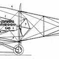
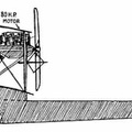
1. Cylinder; 2. Engine Bed; 3. Fuel Tank: 4. Oil Pan; 5. Radiator; 6. Propeller; 7. Crank Case; 8. Carbureter; 9. Gasoline Pipe; 10. Air Intake; 11. Auxiliary Air-pipe; 12. Drain Cock; 13. Water Cooling System; 14. Gas Intake Pipe; 15. Rocker Arm; 16. Spring on Intake Valve; 17. Spring on Exhaust Valve; 18. Exhaust Port; 19. Rocker Arm Post; 20. Push Rod.
- Author
- Title: The Curtiss Aviation Book
Author: Glenn Curtiss, Augustus Post, Paul Beck, Theodore Ellyson and Hugh Robinson
Copyright, 1910, by The Pictorial News Co.
Available from gutenberg.org - Posted on
- Friday 15 October 2021
- Dimensions
- 810*1038
- Tags
- Century:20th , Place:America, Technology
- Albums
- Technology / Transport / Air
- Visits
- 970
- Downloads
- 64
 Download Photo


