


« 2020
2022 »
Janvier
Février
Mars
Avril
Mai
Juin
Juillet
Août
Septembre
Octobre
Novembre
Décembre
Tout

 Fifty years later witnessed the full development of Mr. Bell’s ideal in the Columba, then as now t...") “Columba,” famous Clyde river steamer, 1875
“Columba,” famous Clyde river steamer, 1875
Fifty years later witnessed the full development of Mr. Bell’s ideal in the Columba, then as now the largest river steamer ever seen on the Clyde, and the swiftest. The Columba is built of steel, is 316 feet long and 50 feet wide. She has two oscillating engines of 220 horse-power, and attains a speed of twenty-two miles an hour. Her route is from Glasgow to Ardrishaig and back, daily in summer, when she carries from 2,000 to 3,000 persons through some of the finest scenery in Scotland. She is provided with steam machinery for steering and warping her into the piers, and with other modern appliances that make her as handy as a steam yacht. She resembles a little floating town, with shops and post-office where you can procure money orders and despatch telegrams And what is the Columba after all but an enlarged and perfected reproduction of Bell’s Comet! They found that a slight curve or camber in the wing section would cause the moving air to travel fa...") Wright Brothers' Wind tunnel
Wright Brothers' Wind tunnel
They found that a slight curve or camber in the wing section would cause the moving air to travel farther over the top of the wing surface than along the under side. This made the air pressure greater under the wing, gave a suction effect above the wing, and caused it to rise, creating lift. They discovered that a wing section of the proper camber would counteract the weight of gravity. Thus, a wing must be so designed that, with a certain amount of air flowing around it, it would lift a certain weight. They also discovered that air flow against any surface attached to the wing would cause a resistance or drag. Hundreds of experiments in their wind tunnel with various types of wing shapes gave the Wrights a series of tables from which to design a wing that would create the lift for a designed weight. Out in Dayton, Ohio, there were two small brothers, who dreamed, as countless other children before ...") Wright Brothers' Bicycle shop
Wright Brothers' Bicycle shop
Out in Dayton, Ohio, there were two small brothers, who dreamed, as countless other children before them had dreamed, of flying like birds through the air. Their dreams were heightened by a small toy given to them by their father, the pastor of a local church. This toy was to lead to an idea which had a profound effect on the world. You would probably call it a flying propeller. It consisted of a wooden propeller which slipped over a notched stick. By placing a finger against the propeller and rapidly pushing it up the notched stick, the propeller was made to whirl up off the end of the stick and fly into the air. The brothers, young as they were, never quite forgot this little toy as they continued to dream of flying like birds through the air. Though the brothers continued to dream of flying, they were not the kind of lads who spent all their time in dreaming. They made kites which flew a little better and a little higher than those made by the other boys in the neighborhood. They built a press to print their own little newspaper, and they dabbled in woodcuts. To carve out porch posts for their father’s home they built an eight-foot wood-turning lathe. Indeed, they were the sort of boys who caused the neighbors to say, “What will they think of next?” The brothers knew that if they ever wanted to see their dreams come true they must earn their own capital. In the early nineties America was in the midst of the bicycle craze. Everyone who could possibly afford to do so owned a bicycle of some sort and belonged to a cycle club. Being mechanically minded, the brothers did the logical thing. They set themselves up in a small bicycle shop in Dayton, next door to their home. The bicycle shop in Dayton prospered, for the brothers were careful and expert mechanics, and cyclists in need of repairs made their way to the Wright Brothers’ shop. By 1903 the Wright Brothers were ready to build a powered man-carrying flying machine. Their experim...") Wright Brothers first powered airplane
Wright Brothers first powered airplane
By 1903 the Wright Brothers were ready to build a powered man-carrying flying machine. Their experiments had shown them just how much moving air was necessary to create lift in such a machine. To create the needed thrust, an engine having eight horsepower and weighing not over 200 pounds had to be fitted into the machine. Such an engine was not available, so the Wrights built one in their shop at Dayton, Ohio. They were ready to ship their airplane to Kitty Hawk, N. C., in the fall of 1903. The Wright Brothers were not only inspired mechanics (as many people still believe today) but seriou...") Wright Brotherrs wind tunnel
Wright Brotherrs wind tunnel
The Wright Brothers were not only inspired mechanics (as many people still believe today) but serious scientists, working along the soundest lines. In their keen desire to know what air pressure on wings really was, they cleared a corner of their bicycle shop and built a small wind tunnel with spare lumber and an old electric fan. They built small wing sections of various shapes and experimented with them in their wind tunnel. The electric fan was used to create the moving air around the wing section. By attaching the wing sections to a supporting frame and connecting the frame with a pointer and dial, they were able to keep a record of the effect of moving air on each experimental wing section. Through their wind tunnel research the Wright Brothers discovered the four forces that control all heavier-than-air flight: lift, thrust, weight, and drag. Wolfe, Model A, 24 H.P. H. E. Wilcox Motor Car Company, Minneapolis, Minn.
PRICE: $1,800
BO...") Wolfe, Model A, 24 H.P
Wolfe, Model A, 24 H.P
Wolfe, Model A, 24 H.P. H. E. Wilcox Motor Car Company, Minneapolis, Minn. PRICE: $1,800 BODY: Side entrance, rear seat removable SEATS: 5 persons WEIGHT: 1,900 pounds WHEEL-BASE: 108 inches TREAD: 56 inches TIRES, FRONT: 34 × 3½ inches TIRES, REAR: 34 × 3½ inches STEERING: Worm and sector BRAKES: On rear hubs SPRINGS: Full elliptic FRAME: Pressed steel BORE: 4 in.; STROKE: 4 in. CYLINDERS: 4 vertical, tandem MOTOR SUSPENSION: On sub-frame COOLING: Air IGNITION: Jump spark CURRENT SUPPLY: Battery CARBURETER: Float-feed LUBRICATION: Mechanical force feed MOTOR-CONTROL: Spark and throttle CLUTCH: Cone CHANGE GEAR: Sliding type SPEEDS: 3 forward and reverse CHANGE-GEAR CONTROL: Side lever DRIVE: Side chain NOTE: Runabout body fitted to above chassis for a list of $1,700. Light delivery body also furnished on order.") Walther pistol
Walther pistol Waltham-Orient, Model B R., 4 H.P. Waltham Mfg. Co., Waltham, Mass.
PRICE: $400
BODY: Runab...") Waltham-Orient, Model B R., 4 H.P
Waltham-Orient, Model B R., 4 H.P
Waltham-Orient, Model B R., 4 H.P. Waltham Mfg. Co., Waltham, Mass. PRICE: $400 BODY: Runabout SEATS: 2 persons WEIGHT: 600 pounds WHEEL-BASE: 80 inches TREAD: 42 inches TIRES, FRONT: 26 × 2½ in. TIRES, REAR: 26 × 2½ in. STEERING: Tiller BRAKES: On rear hubs SPRINGS: Elliptical front and rear FRAME: Wood BORE: 3¼ in.; STROKE: 4¼ in. CYLINDERS: One in back VALVE ARRANGEMENT: Automatic inlet; mechanical exhaust MOTOR SUSPENSION: Rear on side members of frame COOLING: Air IGNITION: Jump spark CURRENT SUPPLY: Dry battery CARBURETER: Orient LUBRICATION: Oil pump MOTOR-CONTROL: Throttle and spark CLUTCH: Friction CHANGE GEAR: Friction SPEEDS: 5 forward, 2 reverse CHANGE-GEAR CONTROL: Side lever DRIVE: Friction drive NOTE: Furnished with 2 cylinder motor for $50 extra. Ky, is the Key in its resting position.
c, wherever found, represents a cushion of felt or soft l...") Upright Piano Action
Upright Piano Action
Ky, is the Key in its resting position. c, wherever found, represents a cushion of felt or soft leather upon which the different parts of the action rest or come in contact with each other. Their purpose, as is readily seen, is that of rendering the action noiseless and easy of operation. Bnc R, shows the end of the balance rail, extending the entire length of the keyboard. B P, is the balance pin. This is a perfectly round pin driven firmly in the balance rail. The bottom of the hole in the key fits closely around the balance pin; at the top, it is the shape of a mortise, parallel with the key, which allows the key to move only in the direction intended. The mortise in the wooden cap on top of the key at this point is lined with bushing cloth which holds the key in position laterally, and prevents looseness and rattling, yet allows the key to move easily. Upright action showing lost-motion device, metallic regulating rail support, capstan screw, jack reg...") Upright action showing lost-motion device
Upright action showing lost-motion device
Upright action showing lost-motion device, metallic regulating rail support, capstan screw, jack regulating rail and metallic action brackets. 34. Hammer-rail lifter-wire. 35. Hammer-rail swing-lever. 36. Hammer-rail lifter rod. 37. Lifter-rod lever. 38. Compensation-lever. 39. Capstan-screw. 40. Rail for limiting return movement of jack. 41. Metallic regulating rail support., 1750 (621 visites)") Travelling Posting Carriage (2), 1750
Travelling Posting Carriage (2), 1750, 1750 (667 visites)") Travelling Posting Carriage (1), 1750
Travelling Posting Carriage (1), 1750") Travelling Post, 1825-35
Travelling Post, 1825-35 1. Key.
2. Wippen.
3. Jack.
4. Escapement lever.
5. Hammer-shank.
6. Hammer-b...") The Erard grand action modified by Herz
The Erard grand action modified by Herz
1. Key. 2. Wippen. 3. Jack. 4. Escapement lever. 5. Hammer-shank. 6. Hammer-butt notch. 7. Hammer-head. 8. Jack regulating button. 9. Regulating button to limit rise of escapement lever. 10. Hammer-butt. 11. Check. 12. Molded tail of hammer-head to engage with check. 13. Capstan-screw connecting key and wippen. 14. Action-rails. 15. Damper-head. 16. Damper-operating device. 17. Device to limit travel of jack. 18. Regulating device for escapement lever. 19. Springs (2) for escapement lever and jack. 20. String. 21. Flange. After a year of exhaustive study and experiments with models in their wind tunnel, the Wright Brothe...") The Wright Brothers experimental glider
The Wright Brothers experimental glider
After a year of exhaustive study and experiments with models in their wind tunnel, the Wright Brothers were ready to experiment with a man-carrying glider. With the thoroughness that was typical of every move of the Wrights, the brothers asked the government to let them have information on meteorological conditions all over the country. By studying the weather charts they were able to find a locality where there was a continual flow of wind. This would be nature’s wind tunnel where they could test their glider day after day. Through their study of the charts they found that the wind conditions at Kitty Hawk, on the North Carolina coast, seemed to offer the best possibilities for their glider test. Orville and Wilbur Wright began their experiments with a small man-carrying glider at Kitty Hawk in 1900. From that time until 1903 they made hundreds of successful glider flights and kept accurate records of each flight. They recorded wind velocity, angle of flight, duration of flight, time of day, temperature, humidity, and sky conditions overhead with the typical Wright attention to detail. Each year the Wrights constructed new gliders which embodied principles they had discovered for themselves during their flights at Kitty Hawk. Each glider was larger and had longer and narrower wings than the one before. During the fall of 1902 the brothers recorded nearly a thousand flights in a glider with a wingspan of thirty-two feet. It had a front elevator and a vertical tail which helped to maintain lateral stability. The water tank is seen frequently along the route of the railroads and plenty of water must be taken...") The water tank
The water tank
The water tank is seen frequently along the route of the railroads and plenty of water must be taken on and carried in the engine tender to make steam which is the power used to drive the big engines. The tunnels are passages for trains under mountains, hills and rivers. The tunnels are dark but the ...") The tunnels
The tunnels
The tunnels are passages for trains under mountains, hills and rivers. The tunnels are dark but the trains are well lighted. Electric motors are often used, this avoids the smoke of steam engines which is very unpleasant in the tunnels. The Train Ferry carries entire trains across rivers where there are no bridges. Some of the largest ...") The Train Ferry
The Train Ferry
The Train Ferry carries entire trains across rivers where there are no bridges. Some of the largest train boats have several tracks and carry a train on each. The boats are tied in slips at the shore so that the tracks meet exactly those on the land. The Stage coach is used in the country where towns are few. The stages meet trains at the stations a...") The Stage coach
The Stage coach
The Stage coach is used in the country where towns are few. The stages meet trains at the stations and take on passengers to be carried to their homes away from the railroad. Some of the stage routes are several hundred miles long.") The Situation of the Cavalry man on the near side
The Situation of the Cavalry man on the near side The coaches that travelled between London and distant towns were similar in construction to the hack...") The Machine, 1640-1700
The Machine, 1640-1700
The coaches that travelled between London and distant towns were similar in construction to the hackney coach, which plied for hire in the streets, but were built on a larger scale. They carried eight passengers inside, and behind, over the axle, was a great basket for baggage and outside passengers, who made themselves as comfortable as they might in the straw supplied. The “insides” were protected from rain and cold by leather curtains; neither passengers nor baggage were carried on the roof; and the coachman sat on a bar fixed between the two standard posts from which the body was hung in front, his feet being supported by a footboard on the perch. Mr. Thrupp states that in 1662 there were only six stage coaches in existence; which assertion does not agree with that of Chamberlayne, quoted on a previous page; the seventeenth century writer tells us that in his time—1649—stage coaches ran “from London to the principle towns in the country.” It seems, however, certain that the year 1662 saw a great increase in the number of “short stages”—that is to say, coaches running between London and towns twenty, thirty, forty miles distant.") The Head guarded against any cut
The Head guarded against any cut after testing more than 200 wing designs and plane surfaces in their wind tunnel, the Wright Brother...") The Four forces of flight
The Four forces of flight
after testing more than 200 wing designs and plane surfaces in their wind tunnel, the Wright Brothers found out how to figure correctly the amount of curve, or camber, that was essential to weight-carrying wings. They discovered, too, that before man could be flown through the air, he must have his wings attached firmly to a body or platform which was firm and controllable. The Wrights in their earliest experiments had realized that to be practical their machine must be built not only to fly in a straight line, but also in order that it could be steered to the right or to the left. One day, Orville was twisting a cardboard box in his hand when Wilbur noticed it. Immediately he saw the solution to the problem of steering their airplane. The result was a design which changed the lift of either end of the wing by warping its surface. If one end of the wing was warped to give it more lift, the machine would lift on that side and fall off into a turn. Thus the problem of steering was solved by the Wrights Historians have unearthed stories in cuneiform writing of man’s attempts to fly. Some of these ins...") The flight of Etana
The flight of Etana
Historians have unearthed stories in cuneiform writing of man’s attempts to fly. Some of these inscriptions date back more than five thousand years, to 3500 B.C. Perhaps the most famous of these stories is the ancient Babylonian tale of the shepherd boy, Etana, who rode on the back of an eagle.") The Cut of the Cavalry
The Cut of the Cavalry") The Cut and Thrust in Quarte
The Cut and Thrust in Quarte The driver of a modern-type aeroplane, sitting snugly within its hull, has a wheel and instrument-bo...") The Control of a Biplane
The Control of a Biplane
The driver of a modern-type aeroplane, sitting snugly within its hull, has a wheel and instrument-board before him, as sketched. As he flies across country he has many things to think of. Holding the control-wheel in both hands, his feet resting upon the rudder-bar, his eyes rove constantly among the instruments [Pg 163]on the dashboard before him. He glances at the compass often, for it is by this that he steers; and when the air is clear, and the earth below plainly seen, he will every now and then glance over the side of the hull, so as to be on the look-out for a landmark that may tell him he is on his course. A. Pilot’s seat B. Hand-wheel (pushed forward or backward operates elevator; twisted sideways works ailerons) C. Foot-bar actuating rudder D. Compass E. Dial showing number of revolutions per minute that engine is making F. Gauge showing pressure in petrol tank G. Speed indicator H. Dial showing altitude I. Clock J. Switch for cutting off ignition.") The Cavalry man making point to the right
The Cavalry man making point to the right") the block released
the block released") The Bayonet Exercise
The Bayonet Exercise Langley built his plane without much difficulty, but could not find anyone to make an engine large e...") The Aerodrome
The Aerodrome
Langley built his plane without much difficulty, but could not find anyone to make an engine large enough for it. Finally, Charles Manley, an expert engineer, asked for permission to build the engine. Manley’s engine was a five-cylinder, radial gasoline engine that developed 51 horsepower and was far ahead of its time. It was years before American radial engines were used successfully in airplanes. Professor Langley called his machine the Aerodrome, and by October, 1903, the plane was ready for its test flight, with Manley to guide it. The Aerodrome was to be launched from a catapulting platform built on the roof of a houseboat. The houseboat was anchored on the Potomac River near Washington. As it left the platform the machine crashed into the river, and the trial was a dismal failure. The newspapers and the public ridiculed Langley, but he and Manley, who was unhurt in the crash, repaired the machine for another trial. This test took place on December 8, 1903, and again the Aerodrome crashed into the river. Manley once more escaped injury, but Langley and the government were abused by the public for wasting money. Langley was out of money himself, the government could not furnish funds for further trials, so the experiments were ended. The professor, discouraged and brokenhearted, gave up. During the Crimean War, Boydell’s traction machine was used to haul open trucks on the road and ac...") The 'Hercules' Traction Engine, as used during the Crimean War
The 'Hercules' Traction Engine, as used during the Crimean War
During the Crimean War, Boydell’s traction machine was used to haul open trucks on the road and across country. Its engine, the “Hercules,” was fitted with a curious arrangement, which, by means of rails attached in six sections to the wheels, enabled it to lay down and take up its own track as it went along. Put together scientifically and from sections of wood specially tested, a remarkable strength may be...") Testing the girder-built body of an aircraft
Testing the girder-built body of an aircraft
Put together scientifically and from sections of wood specially tested, a remarkable strength may be obtained by such a method of building. The figure shows how a girder aircraft body, supported by trestles only at its ends, may support from its centre, without yielding, a tray containing a number of heavy weights") Technique of Roman soldier
Technique of Roman soldier Synnestvedt 2-Ton Truck. Synnestvedt Machine Co., Pittsburgh, Pa.
BODY: Stake or van
CAPACI...") Synnestvedt 2-Ton Truck
Synnestvedt 2-Ton Truck
Synnestvedt 2-Ton Truck. Synnestvedt Machine Co., Pittsburgh, Pa. BODY: Stake or van CAPACITY: 2 tons WHEEL-BASE: 87 inches TREAD: 52 inches TIRES, FRONT: 36 × 4 in. TIRES, REAR: 36 × 5 in. BRAKES: On rear wheel and driving shaft SPRINGS: Platform FRAME: Channel steel MOTOR: Synnestvedt electric MOTOR SUSPENSION: In rear under body SPEEDS: 4 forward, 2 reverse DRIVE: Chain In 1801 the London newspapers contained the announcement that an experiment had taken place on the T...") Symington’s ‘Charlotte Dundas,’ 1802
Symington’s ‘Charlotte Dundas,’ 1802
In 1801 the London newspapers contained the announcement that an experiment had taken place on the Thames, on July 1st, for the purpose of propelling a laden barge, or other craft, against the tide, by means of a steam-engine of a very simple construction. “The moment the engine was set to work the barge was brought about, answering her helm quickly, and she made way against a strong current, at the rate of two and a half miles an hour.” In 1802 a new vessel was built expressly for steam navigation, on the Forth and Clyde Canal, under Symington’s supervision, the Charlotte Dundas, which was minutely inspected on the same day by Robert Fulton, of New York, and Henry Bell, of Glasgow, both of whom took sketches of the machinery to good purpose. This boat drew a load of seventy tons, at a speed of three and a half miles an hour, against a strong gale of wind. Under ordinary conditions she made six miles an hour, but her admitted success was cut short by the Canal Trust, who alleged that the wash of the steamer would destroy the embankment.") Stick grenade antipersonnel mine
Stick grenade antipersonnel mine") Stick bomb for use with 3.7 cm Pak
Stick bomb for use with 3.7 cm Pak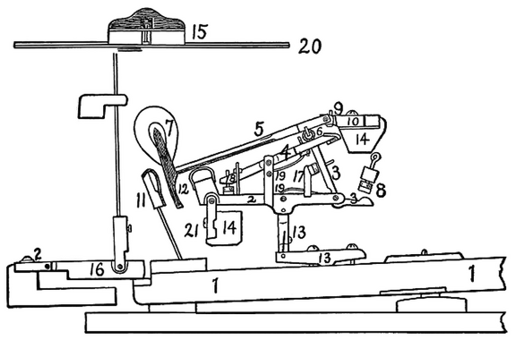 Standard modern American grand action
1. Key. 2. Wippen. 3. Jack. 4. Escapement lever. 5. Hammer-shank. 6. Roller. 7. Hammer-head. 8. Jack-regulating button. 9. Regulating button to limit rise of escapement lever. 10. Hammer-butt. 11. Check. 12. Molded tail of hammer-head to engage with check. 13. Key-rocker and sticker connecting wippen and key. 14. Action-rails. 15. Damper-head. 16. Damper operating device. 17. Device to limit travel of jack. 18. Regulating device for escapement lever. 19. Separate springs for jack and escapement lever. 20. String. 21. Flanges. 1. Key-rocker.
2. Abstract.
3. Abstract-lever.
4. Flange.
5. Action-rail.
6. Wip...") Standard American upright action
Standard American upright action
1. Key-rocker. 2. Abstract. 3. Abstract-lever. 4. Flange. 5. Action-rail. 6. Wippen. 7. Jack. 8. Jack-spring. 9. Check. 10. Check-wire. 11. Bridle-wire. 12. Tip of bridle-tape. 13. Bridle-tape. 14. Back-stop. 15. Regulating rail. 16. Regulating button. 17. Regulating screw. 18. Hammer-butt. 19. Hammer-shank. 20. Hammer-molding. 21. Hammer-head. 22. Hammer-rail. 23. Hammer-butt spring. 24. Hammer-spring rail. 25. Damper-spoon. 26. Damper-lifting rod. 27. Damper-lever. 28. Damper-lever spring. 29. Damper-wire. 30. Damper-block. 31. Damper-head. 32. String. 33. Continuous brass hammer-butt flange. Sovereign, Model M. Matthews Motor Co., Camden, N. J.
BODY: Side entrance tonneau
SEATS: 8 ...") Sovereign, Model M
Sovereign, Model M
Sovereign, Model M. Matthews Motor Co., Camden, N. J. BODY: Side entrance tonneau SEATS: 8 persons WHEEL-BASE: 124 inches TREAD: 56 inches TIRES, FRONT: 36 × 4 inches TIRES, REAR: 36 × 5 inches BRAKES: 2 double internal on rear hubs SPRINGS: Semi-elliptic, front; platform type rear FRAME: Pressed steel BORE: 5½ in.; STROKE: 6 in. CYLINDERS: 4 vertical MOTOR SUSPENSION: From frame COOLING: Water IGNITION Jump spark (double plugs) CURRENT SUPPLY: Magneto and batteries CARBURETER: Automatic LUBRICATION: Mechanical pump MOTOR-CONTROL: Spark and throttle CHANGE GEAR: Sliding type SPEEDS: 4 forward and reverse CHANGE-GEAR CONTROL: Side lever DRIVE: Double side chain") Sketch showing method of inserting loaded belt in feedway of M.G. 34
Sketch showing method of inserting loaded belt in feedway of M.G. 34") Sketch of Stick hand grenade
Sketch of Stick hand grenade Sketch of iron plate for concert grand, showing general arrangement of braces, belly-bridges and sys...") Sketch of iron plate for concert grand
Sketch of iron plate for concert grand
Sketch of iron plate for concert grand, showing general arrangement of braces, belly-bridges and system of bolts for fastening to case. A—B. Hammer line. 1. Body of plate. 2. Bass bridge. 3. Continuous treble bridge. 4. Agraffes. 5. Capo d’astro bar. Plate is cast in one piece and scale is overstrung. (1784 visites)") Sketch of Eierhandgranate 39 (egg-type hand grenade, model 39)
Sketch of Eierhandgranate 39 (egg-type hand grenade, model 39)") Sighting mechanism of 7.5-cm infantry howitzer, showing range-scale drum
Sighting mechanism of 7.5-cm infantry howitzer, showing range-scale drum Joannes Stradanus, born at Bruges 1536, died at Florence 1605, a Flemish historical painter who deli...") Shooting rabbits with the crossbow
Shooting rabbits with the crossbow
Joannes Stradanus, born at Bruges 1536, died at Florence 1605, a Flemish historical painter who delighted in portraying all kinds of sport, such as shooting, hunting, fishing and coursing, which he did with wonderful skill and in most realistic fashion. This picture is reduced from ' Venationes Ferarum,' a work consisting of 105 large plates of sporting scenes, dated 1578. The hunters carry stonebows, and the rabbits are being driven from their burrows by smoke and fire. Purse nets and stop nets may also be seen in use. Following the success of the \"White Wing\" we started in to build another machine, embodying all that...") Scientific American Trophy
Scientific American Trophy
Following the success of the "White Wing" we started in to build another machine, embodying all that we had learned from our experience with the two previous ones. Following our custom of giving each machine a name to distinguish it from the preceding one, we called this third aeroplane the "June Bug." The name was aptly chosen, for it was a success from the very beginning. Indeed, it flew so well that we soon decided it was good enough to win the trophy which had been offered by The Scientific American for the first public flight of one kilometer, or five-eights of a mile, straightaway. This trophy, by the way, was the first to be offered in this country for an aeroplane flight, and the conditions specified that it should become the property of the person winning it three years in succession. The "June Bug" was given a thorough try-out before we made arrangements to fly for the trophy, and we were confident it would fulfill the requirements.") Royal Mail Coach
Royal Mail Coach") rotating crank-catch turned 90°
rotating crank-catch turned 90°") Right view of 8-cm mortar, model 34
Right view of 8-cm mortar, model 34") Right side of 5-cm mortar
Right side of 5-cm mortar") Removal of barrel of M.G. 34
Removal of barrel of M.G. 34 (912 visites)") Racing Deperdussin Monoplane (top view)
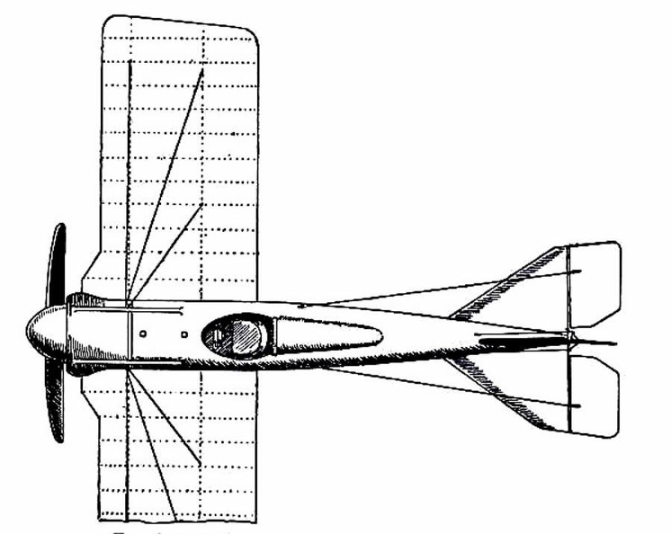
Racing Deperdussin Monoplane (top view) (805 visites) In the development of speed, some remarkable craft are built. Each year there is an international ai...") Racing Deperdussin Monoplane (side view)
Racing Deperdussin Monoplane (side view)
In the development of speed, some remarkable craft are built. Each year there is an international air race for the possession of the Gordon-Bennett trophy, and to win this designers build special craft. In tiny monoplanes, engines of high power are installed; and the sustaining wings are so reduced, to give a maximum speed, that the machines appear more like projectiles than flying craft. A purely racing-type monoplane is seen in figure.. It represents a Deperdussin, which, with an engine of 160 horse-power, reached a speed of 130 miles an hour. How small this machine was, in relation to its engine-power, will be realised from the fact that the sustaining surface of its wings amounted to only 104 square feet—far less lifting area, in fact, than Lilienthal used in his gliders. Wires and struts are reduced to a minimum; the body is tapered and smoothed. Such a machine, although it carries speed to an extreme, and is in reality a “freak,” teaches useful lessons. But though it provides data for the construction of high-speed scouts, a monoplane of this type would be useless for cross-country flying; and for the reason that it cannot be manœuvred, prior to an ascent, upon anything save the smoothest of ground. Its wings being so small, to ensure a maximum of speed, the machine will not rise until it has run forward a long distance across the ground; and during this run it attains a speed of nearly 90 miles an hour. At such a pace, unless the ground below its wheels was level, it would leap, swerve, and probably overturn. When alighting from a flight, also, again owing to the smallness of its wings, the craft has to plane down so fast that its pilot could not land safely unless he had below him a surface that was absolutely smooth. A. Propeller B. Shield to lessen wind resistance C. Sloping shield which encloses engine (also to minimise wind-pressure). Air passes between the shields B and C to cool the motor. D. Pilot’s seat E. Padded projection against which, when at high speed, the pilot rests his head F. Sustaining-plane Very slightly cambered G. Rudder H. Elevating-plane I. Landing wheels.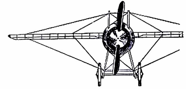
 (813 visites) showing the “stream-line” effect which is gained by tapering the body, also the simplification o...") Racing Deperdussin Monoplane (front view)
Racing Deperdussin Monoplane (front view)
showing the “stream-line” effect which is gained by tapering the body, also the simplification of the landing chassis, and the use of a minimum of wires. photo id=7984] R & L Stanhope. Rauch and Lang Carriage Co., Cleveland, Ohio
PRICE: $1,850
BODY: Stanhope
...") R & L Stanhope
R & L Stanhope
R & L Stanhope. Rauch and Lang Carriage Co., Cleveland, Ohio PRICE: $1,850 BODY: Stanhope SEATS: 2 persons WEIGHT: 1,600 pounds WHEEL-BASE: 73 inches TIRES, FRONT: 32 in., pneumatic TIRES, REAR: 32 in., pneumatic STEERING: Side lever BRAKES: On rear wheels and emergency SPRINGS: Semi-elliptic front; full elliptic rear FRAME: Steel HORSE-POWER: 1½ MOTOR: Hertner MOTOR SUSPENSION: Under body SPEED: 1–22 m. p. h. DISTANCE: 75 to 80 miles MOTOR-CONTROL: Lever at left of seat DRIVE: Double chain from countershaft This venerable instrument, the least impaired Gaelic Harp existing, is known as Queen Mary's Harp.
...") Queen Mary's Harp
Queen Mary's Harp
This venerable instrument, the least impaired Gaelic Harp existing, is known as Queen Mary's Harp. It is small, being only 31 inches high and 18 inches from back to front. It was played resting upon the left knee and against the left shoulder of the performer, whose left hand touched the upper strings. The comb is from 2½ to 3¼ inches high. It is inserted obliquely in the sound chest, and projects about 14 inches. Queen Elizabeth travelled in a coach, either the one built by Walter Rippon or that brought by Boone...") Queen Elizabeth’s Travelling Coach
Queen Elizabeth’s Travelling Coach
Queen Elizabeth travelled in a coach, either the one built by Walter Rippon or that brought by Boonen (who, by the way, was appointed her coachman), on some of her royal progresses through the kingdom. When she visited Warwick in 1572, at the request of the High Bailiff she “caused every part and side of the coach to be opened that all her subjects present might behold her, which most gladly they desired.” The vehicle which could thus be opened on “every part and side” is depicted incidentally in a work executed by Hoefnagel in 1582, which Markland believed to be probably the first engraved representation of an English coach. As will be seen from the reproduction here given, the body carried a roof or canopy on pillars, and the intervening spaces could be closed by means of curtains.") Quarte
Quarte