


 The story of Dædalus and Icarus also tells us that man believed flying was somehow possible. Dædal...") Daedalus and Icarus
Daedalus and Icarus
The story of Dædalus and Icarus also tells us that man believed flying was somehow possible. Dædalus was a very clever man who lived with his son Icarus on the Island of Crete. The king of this island requested Dædalus to build a labyrinth or maze for him. Dædalus constructed the labyrinth so cleverly that only the king, who had the clue to the winding passages, could find his way out. One day the king became very angry at Dædalus and threw both him and his son Icarus into the labyrinth, intending that they should perish. Dædalus, who had been dreaming of flying, fashioned wings from wax and feathers, with which he and Icarus could fly to freedom. He cautioned Icarus that he must not fly too high or the sun would melt the wax in his wings. Icarus, impatient to escape, scarcely listened. Like birds the two flew into the air, quickly leaving the walls of the labyrinth. Dædalus, flying low, safely crossed the sea and reached Sicily. Icarus, unfortunately, failed to heed his father’s warning. Flying was so much fun that he rose higher and higher. Suddenly feathers began to drop one by one. Too late Icarus realized that the sun had melted the wax in his wings. Down, down he fell into the sea. Historians have unearthed stories in cuneiform writing of man’s attempts to fly. Some of these ins...") The flight of Etana
The flight of Etana
Historians have unearthed stories in cuneiform writing of man’s attempts to fly. Some of these inscriptions date back more than five thousand years, to 3500 B.C. Perhaps the most famous of these stories is the ancient Babylonian tale of the shepherd boy, Etana, who rode on the back of an eagle. In 1678, Besnier, a French locksmith, constructed a curious flying machine consisting of two wooden ...") Besnier and his wings
Besnier and his wings
In 1678, Besnier, a French locksmith, constructed a curious flying machine consisting of two wooden bars which rested on his shoulders. At the ends of the bars he attached muslin wings, arranged to open on the down stroke and close on the up stroke. The wings were operated by moving the arms and legs. Although Besnier failed to realize that no man had sufficient muscular strength to fly as the bird flies, he did sense part of the truth—that gliding with the air currents was possible. During his experiments he is said to have jumped from a window sill, glided over the roof of a near-by cottage, and landed on a barge in the river. Leonardo da Vinci, the great Italian artist and scientist, who lived in the fifteenth century, spent...") Leonardo da Vinci's Glider and Parachute Idea
Leonardo da Vinci's Glider and Parachute Idea
Leonardo da Vinci, the great Italian artist and scientist, who lived in the fifteenth century, spent years experimenting with the idea of flying. He made a number of sketches of wings to be fitted to the arms and legs of man. His plan for a parachute was soundly worked out and his idea that the wings of a flying machine should be patterned after the wings of the bat found expression in the doped fabric covering of our early airplanes. Octave Chanute, born in France and reared in America, was one of the first men to make a scientific ...") Octave Chanute experimenting with his gliders on the Michigan sand dunes
Octave Chanute experimenting with his gliders on the Michigan sand dunes
Octave Chanute, born in France and reared in America, was one of the first men to make a scientific approach to the problem of flying machines. A thorough scientist, he had followed the progress of all flight experiments the world over. He built gliders with one, two, and even five pairs of wings and tested all of them on the sand dunes of Lake Michigan. His most successful glides were made with a biplane glider. In 1894, he published a book called Progress of Flying Machines, which covered all the efforts of men like himself who had experimented with man-carrying gliders and flying machines. Langley built his plane without much difficulty, but could not find anyone to make an engine large e...") The Aerodrome
The Aerodrome
Langley built his plane without much difficulty, but could not find anyone to make an engine large enough for it. Finally, Charles Manley, an expert engineer, asked for permission to build the engine. Manley’s engine was a five-cylinder, radial gasoline engine that developed 51 horsepower and was far ahead of its time. It was years before American radial engines were used successfully in airplanes. Professor Langley called his machine the Aerodrome, and by October, 1903, the plane was ready for its test flight, with Manley to guide it. The Aerodrome was to be launched from a catapulting platform built on the roof of a houseboat. The houseboat was anchored on the Potomac River near Washington. As it left the platform the machine crashed into the river, and the trial was a dismal failure. The newspapers and the public ridiculed Langley, but he and Manley, who was unhurt in the crash, repaired the machine for another trial. This test took place on December 8, 1903, and again the Aerodrome crashed into the river. Manley once more escaped injury, but Langley and the government were abused by the public for wasting money. Langley was out of money himself, the government could not furnish funds for further trials, so the experiments were ended. The professor, discouraged and brokenhearted, gave up. Out in Dayton, Ohio, there were two small brothers, who dreamed, as countless other children before ...") Wright Brothers' Bicycle shop
Wright Brothers' Bicycle shop
Out in Dayton, Ohio, there were two small brothers, who dreamed, as countless other children before them had dreamed, of flying like birds through the air. Their dreams were heightened by a small toy given to them by their father, the pastor of a local church. This toy was to lead to an idea which had a profound effect on the world. You would probably call it a flying propeller. It consisted of a wooden propeller which slipped over a notched stick. By placing a finger against the propeller and rapidly pushing it up the notched stick, the propeller was made to whirl up off the end of the stick and fly into the air. The brothers, young as they were, never quite forgot this little toy as they continued to dream of flying like birds through the air. Though the brothers continued to dream of flying, they were not the kind of lads who spent all their time in dreaming. They made kites which flew a little better and a little higher than those made by the other boys in the neighborhood. They built a press to print their own little newspaper, and they dabbled in woodcuts. To carve out porch posts for their father’s home they built an eight-foot wood-turning lathe. Indeed, they were the sort of boys who caused the neighbors to say, “What will they think of next?” The brothers knew that if they ever wanted to see their dreams come true they must earn their own capital. In the early nineties America was in the midst of the bicycle craze. Everyone who could possibly afford to do so owned a bicycle of some sort and belonged to a cycle club. Being mechanically minded, the brothers did the logical thing. They set themselves up in a small bicycle shop in Dayton, next door to their home. The bicycle shop in Dayton prospered, for the brothers were careful and expert mechanics, and cyclists in need of repairs made their way to the Wright Brothers’ shop. The Wright Brothers were not only inspired mechanics (as many people still believe today) but seriou...") Wright Brotherrs wind tunnel
Wright Brotherrs wind tunnel
The Wright Brothers were not only inspired mechanics (as many people still believe today) but serious scientists, working along the soundest lines. In their keen desire to know what air pressure on wings really was, they cleared a corner of their bicycle shop and built a small wind tunnel with spare lumber and an old electric fan. They built small wing sections of various shapes and experimented with them in their wind tunnel. The electric fan was used to create the moving air around the wing section. By attaching the wing sections to a supporting frame and connecting the frame with a pointer and dial, they were able to keep a record of the effect of moving air on each experimental wing section. Through their wind tunnel research the Wright Brothers discovered the four forces that control all heavier-than-air flight: lift, thrust, weight, and drag. They found that a slight curve or camber in the wing section would cause the moving air to travel fa...") Wright Brothers' Wind tunnel
Wright Brothers' Wind tunnel
They found that a slight curve or camber in the wing section would cause the moving air to travel farther over the top of the wing surface than along the under side. This made the air pressure greater under the wing, gave a suction effect above the wing, and caused it to rise, creating lift. They discovered that a wing section of the proper camber would counteract the weight of gravity. Thus, a wing must be so designed that, with a certain amount of air flowing around it, it would lift a certain weight. They also discovered that air flow against any surface attached to the wing would cause a resistance or drag. Hundreds of experiments in their wind tunnel with various types of wing shapes gave the Wrights a series of tables from which to design a wing that would create the lift for a designed weight. after testing more than 200 wing designs and plane surfaces in their wind tunnel, the Wright Brother...") The Four forces of flight
The Four forces of flight
after testing more than 200 wing designs and plane surfaces in their wind tunnel, the Wright Brothers found out how to figure correctly the amount of curve, or camber, that was essential to weight-carrying wings. They discovered, too, that before man could be flown through the air, he must have his wings attached firmly to a body or platform which was firm and controllable. The Wrights in their earliest experiments had realized that to be practical their machine must be built not only to fly in a straight line, but also in order that it could be steered to the right or to the left. One day, Orville was twisting a cardboard box in his hand when Wilbur noticed it. Immediately he saw the solution to the problem of steering their airplane. The result was a design which changed the lift of either end of the wing by warping its surface. If one end of the wing was warped to give it more lift, the machine would lift on that side and fall off into a turn. Thus the problem of steering was solved by the Wrights After a year of exhaustive study and experiments with models in their wind tunnel, the Wright Brothe...") The Wright Brothers experimental glider
The Wright Brothers experimental glider
After a year of exhaustive study and experiments with models in their wind tunnel, the Wright Brothers were ready to experiment with a man-carrying glider. With the thoroughness that was typical of every move of the Wrights, the brothers asked the government to let them have information on meteorological conditions all over the country. By studying the weather charts they were able to find a locality where there was a continual flow of wind. This would be nature’s wind tunnel where they could test their glider day after day. Through their study of the charts they found that the wind conditions at Kitty Hawk, on the North Carolina coast, seemed to offer the best possibilities for their glider test. Orville and Wilbur Wright began their experiments with a small man-carrying glider at Kitty Hawk in 1900. From that time until 1903 they made hundreds of successful glider flights and kept accurate records of each flight. They recorded wind velocity, angle of flight, duration of flight, time of day, temperature, humidity, and sky conditions overhead with the typical Wright attention to detail. Each year the Wrights constructed new gliders which embodied principles they had discovered for themselves during their flights at Kitty Hawk. Each glider was larger and had longer and narrower wings than the one before. During the fall of 1902 the brothers recorded nearly a thousand flights in a glider with a wingspan of thirty-two feet. It had a front elevator and a vertical tail which helped to maintain lateral stability. By 1903 the Wright Brothers were ready to build a powered man-carrying flying machine. Their experim...") Wright Brothers first powered airplane
Wright Brothers first powered airplane
By 1903 the Wright Brothers were ready to build a powered man-carrying flying machine. Their experiments had shown them just how much moving air was necessary to create lift in such a machine. To create the needed thrust, an engine having eight horsepower and weighing not over 200 pounds had to be fitted into the machine. Such an engine was not available, so the Wrights built one in their shop at Dayton, Ohio. They were ready to ship their airplane to Kitty Hawk, N. C., in the fall of 1903. A more general interest in the subject was revived in England by the work of James Blundell, lecture...") Blundell’s Impellor
Blundell’s Impellor
A more general interest in the subject was revived in England by the work of James Blundell, lecturer on physiology and midwifery at St. Thomas’s and Guy’s Hospitals. He published in 1818 his earliest paper on experimental transfusion with a special form of syringe invented by himself. His first apparatus consisted of a funnel-shaped receptacle for the blood, connected by a two-way tap with a syringe from which the blood was injected through a tube and cannula into the recipient. His experiments were[11] performed upon dogs, and he began by drawing blood from the femoral artery and re-injecting it into the same animal through the femoral vein. He then conducted a long series of investigations into the properties of blood, the effects of its withdrawal, and the resuscitation of an exsanguinated animal. Soon he had opportunities of transfusing patients with human blood, and the results are recorded in his paper of 1824. His apparatus had by then been elaborated, and an engraving of his Impellor, as he termed it, is reproduced here. It consisted as before of a funnel-shaped receptacle for the blood, but the syringe was now incorporated in one side of the funnel, and contained a complicated system of spring valves, which caused the blood to travel along the delivery tube when the piston was pushed down. The Impellor was fixed to the back of a chair in order to give it stability. When the donor’s arm has been congested by gripping it above the elbow, or better by the applicati...") Drawing Blood for Transfusion
Drawing Blood for Transfusion
When the donor’s arm has been congested by gripping it above the elbow, or better by the application of a tourniquet drawn to the requisite degree of tightness, a suitable vein, usually the median basilic, is chosen. The area of puncture is washed with ether and a very small quantity, 2 to 3 minims, of 2 per cent. novocain is introduced over the vein with a hypodermic syringe. If a larger quantity is used, the vein may become obscured, but this small amount may be dispersed by a few moments’ pressure with the finger, and is usually enough to anæsthetize the very small area of skin that is to be operated upon. A tiny cut in the skin is then made with the point of a scalpel, and the needle is pushed through into the vein. Whole Blood Transfusion with Kimpton’s Tube.
The principle of this method depends upon the use ...") Kimpton-Brown Tube
Kimpton-Brown Tube
Whole Blood Transfusion with Kimpton’s Tube. The principle of this method depends upon the use of paraffin wax as a coating for the vessel into which the blood is drawn, so that clotting is prevented or greatly delayed. The form of the vessel has been modified by different workers, but the essentials are the same in each. One form of the apparatus, known as the Kimpton-Brown tube, is illustrated in the accompanying diagram. It consists of a graduated glass cylinder, of about 700 cc. capacity, the lower end of which is drawn out into a cannula point at an acute angle with the body of the cylinder; the point is of a size convenient for introducing into a vein and its bore large enough to allow of a free flow of blood through it. Near the upper end is a side tube to which a rubber tube can be attached, and an opening at the top is closed by a rubber bung. An ordinary rubber double-bulb bellows is the only other apparatus that is needed. Mr. Higginson’s Transfusion Instrument
Although some of the early experiments on blood transfus...") Mr. Higginson’s Transfusion Instrument
Mr. Higginson’s Transfusion Instrument
Mr. Higginson’s Transfusion Instrument Although some of the early experiments on blood transfusion had been done in England, and although its revival [14]in the nineteenth century was initiated in England, yet it is to be noticed that most of the references to it up to 1874 are to be found in the works of Continental writers. Nevertheless, an important modification was introduced into the technique of the operation in 1857 by Higginson, who applied the principle of a rubber syringe with ball-valves for transferring the blood from the receptacle into which it was drawn, to the vein of the recipient. This apparatus is illustrated here, as it is of some interest in the history of medicine. A is a metallic cup, of 6-oz. capacity, to receive the supply of blood. B an outer casing, which will hold 5 oz. of hot water, introduced through an aperture at C. D is a passage leading into an elastic barrel, composed of vulcanized india-rubber, E, of which the capacity is 1 oz. F′ the exit for the blood into the injection-pipe G. At D and F there are ball-valves, capable of closing the upper openings when thrown up against them, but leaving the lower openings always free. The blood, or other fluid, poured into the cup A, has free power to run unobstructed through D, E, F; a small plug H is therefore provided to close the lower aperture F when necessary. The tube G is of vulcanized india-rubber, and terminates in a metal tube O for insertion into the vein. The water tank is seen frequently along the route of the railroads and plenty of water must be taken...") The water tank
The water tank
The water tank is seen frequently along the route of the railroads and plenty of water must be taken on and carried in the engine tender to make steam which is the power used to drive the big engines. An observation train is often made up to follow the great college boat races, where the railroad run...") An observation train
An observation train
An observation train is often made up to follow the great college boat races, where the railroad runs along the river bank. Flat cars are used with seats fixed on them for the spectators. The Train Ferry carries entire trains across rivers where there are no bridges. Some of the largest ...") The Train Ferry
The Train Ferry
The Train Ferry carries entire trains across rivers where there are no bridges. Some of the largest train boats have several tracks and carry a train on each. The boats are tied in slips at the shore so that the tracks meet exactly those on the land. The Stage coach is used in the country where towns are few. The stages meet trains at the stations a...") The Stage coach
The Stage coach
The Stage coach is used in the country where towns are few. The stages meet trains at the stations and take on passengers to be carried to their homes away from the railroad. Some of the stage routes are several hundred miles long. The tunnels are passages for trains under mountains, hills and rivers. The tunnels are dark but the ...") The tunnels
The tunnels
The tunnels are passages for trains under mountains, hills and rivers. The tunnels are dark but the trains are well lighted. Electric motors are often used, this avoids the smoke of steam engines which is very unpleasant in the tunnels.") Field Artillery
Field Artillery 1. Key-rocker.
2. Abstract.
3. Abstract-lever.
4. Flange.
5. Action-rail.
6. Wip...") Standard American upright action
Standard American upright action
1. Key-rocker. 2. Abstract. 3. Abstract-lever. 4. Flange. 5. Action-rail. 6. Wippen. 7. Jack. 8. Jack-spring. 9. Check. 10. Check-wire. 11. Bridle-wire. 12. Tip of bridle-tape. 13. Bridle-tape. 14. Back-stop. 15. Regulating rail. 16. Regulating button. 17. Regulating screw. 18. Hammer-butt. 19. Hammer-shank. 20. Hammer-molding. 21. Hammer-head. 22. Hammer-rail. 23. Hammer-butt spring. 24. Hammer-spring rail. 25. Damper-spoon. 26. Damper-lifting rod. 27. Damper-lever. 28. Damper-lever spring. 29. Damper-wire. 30. Damper-block. 31. Damper-head. 32. String. 33. Continuous brass hammer-butt flange. Upright action showing lost-motion device, metallic regulating rail support, capstan screw, jack reg...") Upright action showing lost-motion device
Upright action showing lost-motion device
Upright action showing lost-motion device, metallic regulating rail support, capstan screw, jack regulating rail and metallic action brackets. 34. Hammer-rail lifter-wire. 35. Hammer-rail swing-lever. 36. Hammer-rail lifter rod. 37. Lifter-rod lever. 38. Compensation-lever. 39. Capstan-screw. 40. Rail for limiting return movement of jack. 41. Metallic regulating rail support. Grand pianoforte action with metallic action and damper frames, sostenuto pedal device and hammer ...") Grand pianoforte action with metallic action and damper frames
Grand pianoforte action with metallic action and damper frames
Grand pianoforte action with metallic action and damper frames, sostenuto pedal device and hammer swinging soft pedal attachment. 22. Sostenuto pedal-rod. 23. Attachment to damper-lever engaging with sostenuto pedal-rod. 24. Metallic action and damper-brackets. 25. Hammer swing-rail and cushion. 26. Hammer swing-rail rod. 27. Hammer swing-rail lifter. 28. Lifter-rod. 29. Lost motion compensating levers. 30. Lost motion compensating levers.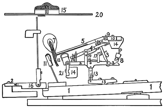 Standard modern American grand action
1. Key. 2. Wippen. 3. Jack. 4. Escapement lever. 5. Hammer-shank. 6. Roller. 7. Hammer-head. 8. Jack-regulating button. 9. Regulating button to limit rise of escapement lever. 10. Hammer-butt. 11. Check. 12. Molded tail of hammer-head to engage with check. 13. Key-rocker and sticker connecting wippen and key. 14. Action-rails. 15. Damper-head. 16. Damper operating device. 17. Device to limit travel of jack. 18. Regulating device for escapement lever. 19. Separate springs for jack and escapement lever. 20. String. 21. Flanges.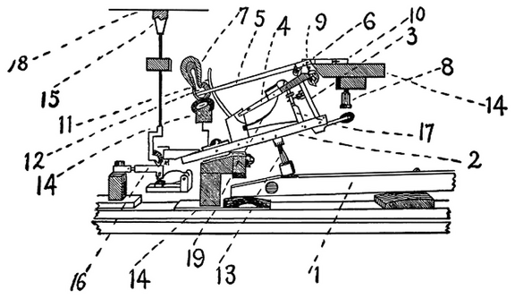 Double repetition action of Sebastian Erard as used by S. & P. Erard, Paris
1. Key. 2. Wippen. 3. Jack. 4. Escapement lever. 5. Hammer-shank. 6. Roller. 7. Hammer-head. 8. Jack regulating button. 9. Regulating button to limit rise of escapement lever. 10. Hammer-butt. 11. Check. 12. Felt cushion to engage with check. 13. Sticker connecting key and wippen. 14. Action-rails. 15. Damper-head. 16. Damper operating device. 17. Device to limit travel of jack. 18. String. 19. Spring (v-shaped) for escapement lever and jack. 1. Key.
2. Wippen.
3. Jack.
4. Escapement lever.
5. Hammer-shank.
6. Hammer-b...") The Erard grand action modified by Herz
The Erard grand action modified by Herz
1. Key. 2. Wippen. 3. Jack. 4. Escapement lever. 5. Hammer-shank. 6. Hammer-butt notch. 7. Hammer-head. 8. Jack regulating button. 9. Regulating button to limit rise of escapement lever. 10. Hammer-butt. 11. Check. 12. Molded tail of hammer-head to engage with check. 13. Capstan-screw connecting key and wippen. 14. Action-rails. 15. Damper-head. 16. Damper-operating device. 17. Device to limit travel of jack. 18. Regulating device for escapement lever. 19. Springs (2) for escapement lever and jack. 20. String. 21. Flange., Streicher Viennese escapement (1794) (865 visits) 1. Key.
2. Jack.
3. Jack-operating spring.
4. Cushion limiting rebound of jack.
5...") Action by Andreas and Nanette (Stein), Streicher Viennese escapement (1794)
Action by Andreas and Nanette (Stein), Streicher Viennese escapement (1794)
1. Key. 2. Jack. 3. Jack-operating spring. 4. Cushion limiting rebound of jack. 5. Button and screw regulating escapement of hammer. 6. Hammer-butt and operating face. 7. Hammer-butt pivot. 8. Hammer-shank. 9. Hammer-head. 10. Check. 11. Damper-lifter. 12. Damper-head. 13. Action-rails. (885 visits) 1. Key.
2. Jack.
3. Jack operating spring.
4. Rail and cushion limiting travel of jac...") English direct lever grand action, developed by Broadwood from Backers (1884)
English direct lever grand action, developed by Broadwood from Backers (1884)
1. Key. 2. Jack. 3. Jack operating spring. 4. Rail and cushion limiting travel of jack. 5. Button and screw regulating escapement of hammer. 6. Hammer-butt with operating notch. 7. Hammer-butt flange. 8. Hammer-shank. 9. Hammer-head. 10. Check. 13. Action-rails. 1. Key.
2. Jack.
3. Jack-operating spring.
4. Cushion limiting rebound of jack.
5...") Cristofori’s action in its final form
Cristofori’s action in its final form
1. Key. 2. Jack. 3. Jack-operating spring. 4. Cushion limiting rebound of jack. 5. Under-hammer. 6. Hammer-butt. 7. Hinge of hammer-butt. 8. Hammer-shank. 9. Hammer head. 10. Check. 11. Damper-lifter. 12. Damper-head. 13. Action-beam. 14. Wrest-plank. 15. Tuning pins. 16. Bearing-bridge. 17. String. (812 visits)") Iron plate for upright pianoforte with Agraffes (Mehlin patents)
Iron plate for upright pianoforte with Agraffes (Mehlin patents)") Arrangement of iron plate, braces and scale of parlor size grand pianoforte
Arrangement of iron plate, braces and scale of parlor size grand pianoforte") Iron plate for upright pianoforte fitted with Capo D’astro bar
Iron plate for upright pianoforte fitted with Capo D’astro bar Sketch of iron plate for concert grand, showing general arrangement of braces, belly-bridges and sys...") Sketch of iron plate for concert grand
Sketch of iron plate for concert grand
Sketch of iron plate for concert grand, showing general arrangement of braces, belly-bridges and system of bolts for fastening to case. A—B. Hammer line. 1. Body of plate. 2. Bass bridge. 3. Continuous treble bridge. 4. Agraffes. 5. Capo d’astro bar. Plate is cast in one piece and scale is overstrung. Back view of upright pianoforte, Knabe patents, showing ribbing of sound-board and construction of b...") Back view of upright pianoforte
Back view of upright pianoforte
Back view of upright pianoforte, Knabe patents, showing ribbing of sound-board and construction of back framing.") Jonas Chickering’s full solid cast grand metal plate
Jonas Chickering’s full solid cast grand metal plate A. Continuous bent rim.
B. Wooden struts.
C. Iron shoe holding struts and connecting with iron pla...") Modern method og grand pianoforte case construction
Modern method og grand pianoforte case construction
A. Continuous bent rim. B. Wooden struts. C. Iron shoe holding struts and connecting with iron plate. D. Main beam. Last of the Clipper Passenger Packets, 1854.
The clipper “packet ship” was a vast improvement...") 'Great Republic'
'Great Republic'
Last of the Clipper Passenger Packets, 1854. The clipper “packet ship” was a vast improvement on the ordinary sailing ship. It had just reached its highest point of development when the ocean steamship first made its appearance. It was to the upper strata of the travelling community, sixty years ago, the counterpart of the express steamer of to-day. The packet-ship was built for fast sailing, with very fine lines, was handsomely fitted up and furnished, was exceedingly well found in eatables and drinkables, and carried a great spread of canvas. To see one of these ships under full sail was a [Pg 27]sight to be remembered—a rare sight, inasmuch as all the conditions of wind and water necessary for the display of every stitch of canvas are seldom met with in the North Atlantic. They not unfrequently crossed in fourteen or fifteen days. In winter they might be three months on a single voyage, but their average would be from twenty-five to thirty days. Paddle-wheels for driving boats through the water were used long before steam-engines were thought o...") Horse-boat at Empy’s Ferry, Osnabruck, Ontario
Horse-boat at Empy’s Ferry, Osnabruck, Ontario
Paddle-wheels for driving boats through the water were used long before steam-engines were thought of. They were worked by hand and foot-power without, however, any advantage over the old-fashioned oar. The horse-boat, in a variety of forms, has been in use for many years, and is not yet quite obsolete. In its earlier form two horses, one on each side of a decked scow, were hitched to firmly braced upright posts at which they tugged for all they were worth without ever advancing beyond their noses, but communicating motion to the paddle-wheels by the movable platform on which they trod. For larger boats four or five horses were harnessed to horizontal bars converging towards the centre, and moved around the deck in a circle, the paddles receiving their impulse through a set of cog-wheels. An experiment was made by Patrick Miller, a banker in Edinburgh, aided by Mr. Taylor, tutor in his f...") Miller’s twin boat on Loch Dalswinton, 1788
Miller’s twin boat on Loch Dalswinton, 1788
An experiment was made by Patrick Miller, a banker in Edinburgh, aided by Mr. Taylor, tutor in his family, and Alexander Symington, a practical engineer. Mr. Miller had a boat built and fitted with a small steam-engine, for his amusement, on Dalswinton Loch, Dumfriesshire. It was a twin-boat, the engine being placed on one side, the boiler on the other, and the paddle-wheel in the centre. It was launched in October, 1788, and attained a speed of five miles an hour. The engine, of one horse-power, is still to be seen in the Andersonian Museum, in Glasgow. Encouraged by his experiment, Mr. Miller bought one of the boats used on the Forth and Clyde Canal, and had a steam-engine constructed for it by the Carron Ironworks Company, under Symington’s superintendence. On December 26th, 1789, this steamboat towed a heavy load on the canal, at a speed of seven miles an hour; but, strange to say, the experiment was dropped as soon as it was tried. In 1801 the London newspapers contained the announcement that an experiment had taken place on the T...") Symington’s ‘Charlotte Dundas,’ 1802
Symington’s ‘Charlotte Dundas,’ 1802
In 1801 the London newspapers contained the announcement that an experiment had taken place on the Thames, on July 1st, for the purpose of propelling a laden barge, or other craft, against the tide, by means of a steam-engine of a very simple construction. “The moment the engine was set to work the barge was brought about, answering her helm quickly, and she made way against a strong current, at the rate of two and a half miles an hour.” In 1802 a new vessel was built expressly for steam navigation, on the Forth and Clyde Canal, under Symington’s supervision, the Charlotte Dundas, which was minutely inspected on the same day by Robert Fulton, of New York, and Henry Bell, of Glasgow, both of whom took sketches of the machinery to good purpose. This boat drew a load of seventy tons, at a speed of three and a half miles an hour, against a strong gale of wind. Under ordinary conditions she made six miles an hour, but her admitted success was cut short by the Canal Trust, who alleged that the wash of the steamer would destroy the embankment. Nothing more was heard of the steamboat in Britain until 1812, when Henry Bell surprised the natives...") Bell’s ‘Comet,’ off Dumbarton on the Clyde, 1812
Bell’s ‘Comet,’ off Dumbarton on the Clyde, 1812
Nothing more was heard of the steamboat in Britain until 1812, when Henry Bell surprised the natives of Strathclyde by the following advertisement in the Greenock Advertiser: STEAM PASSAGE BOAT, “THE COMET,” Between Glasgow, Greenock and Helensburgh, for Passengers Only. The subscriber having, at much expense, fitted up a handsome vessel, to ply upon the River Clyde, between Glasgow and Greenock, to sail by the power of wind, air and steam, he intends that the vessel shall leave the Broomielaw on Tuesdays, Thursdays and Saturdays, about mid-day, or at such hour thereafter as may answer from the state of the tide; and to leave Greenock on Mondays, Wednesdays and Fridays, in the morning, to suit the tide. The elegance, comfort, safety and speed of this vessel requires only to be proved to meet the approbation of the public; and the proprietor is determined to do everything in his power to merit public encouragement. The terms are, for the present, fixed at 4s. for the best cabin, and 3s. for the second; but beyond these rates nothing is to be allowed to servants, or any other person employed about the vessel. The subscriber continues his establishment at Helensburgh Baths, the same as for years past, and a vessel will be in readiness to convey passengers to the Comet from Greenock to Helensburgh. Henry Bell. Helensburgh Baths, 5th August, 1812. Fifty years later witnessed the full development of Mr. Bell’s ideal in the Columba, then as now t...") “Columba,” famous Clyde river steamer, 1875
“Columba,” famous Clyde river steamer, 1875
Fifty years later witnessed the full development of Mr. Bell’s ideal in the Columba, then as now the largest river steamer ever seen on the Clyde, and the swiftest. The Columba is built of steel, is 316 feet long and 50 feet wide. She has two oscillating engines of 220 horse-power, and attains a speed of twenty-two miles an hour. Her route is from Glasgow to Ardrishaig and back, daily in summer, when she carries from 2,000 to 3,000 persons through some of the finest scenery in Scotland. She is provided with steam machinery for steering and warping her into the piers, and with other modern appliances that make her as handy as a steam yacht. She resembles a little floating town, with shops and post-office where you can procure money orders and despatch telegrams And what is the Columba after all but an enlarged and perfected reproduction of Bell’s Comet! The Rhine steamers and those plying on the Swiss lakes are in keeping with the picturesque scenery t...") 'Wilhelm Kaiser' On The Rhine, 1886
'Wilhelm Kaiser' On The Rhine, 1886
The Rhine steamers and those plying on the Swiss lakes are in keeping with the picturesque scenery through which they run. Painted in bright colours, they present a very attractive and smart appearance. They are kept scrupulously clean and are admirably managed. Many of them are large, with saloon cabins the whole length of the vessel, over which is the promenade deck covered with gay awnings. They run fast. The captain sits in state in his easy chair under a canopy on the bridge—smoking his cigar. The chief steward, next to the captain by far the most important personage on board, moves about all day long in full evening dress—his main concern being to know what wine you will have for lunch or dinner that he may put it on ice for you. The table d’hote is the crowning event of the day on board a Rhine steamer, i.e., for the misguided majority of tourists to whom a swell dinner offers greater attractions than the finest scenery imaginable. The Clermont made her first voyage from New York to Albany, August 7th, 1807.
Her speed was about ...") Fulton’s ‘Clermont’ on The Hudson, 1807
Fulton’s ‘Clermont’ on The Hudson, 1807
The Clermont made her first voyage from New York to Albany, August 7th, 1807. Her speed was about five miles an hour. During the winter of 1807-8 she was enlarged, her name being then changed to North River. She continued to ply successfully on the Hudson as a passenger boat for a number of years, her owners having acquired the exclusive right to navigate the waters of the State of New York by steam. The light-draught Mississippi steamers bear little resemblance to the Hudson River and Long Island S...") Mississippi steamboat ‘J. M. White,’ 1878
Mississippi steamboat ‘J. M. White,’ 1878
The light-draught Mississippi steamers bear little resemblance to the Hudson River and Long Island Sound boats while the American steam ferry-boat is a thing certainly not of beauty, but unique. The J. M. White, of 1878, was deemed “a crowning effort in steamboat architecture in the West.” She was 320 feet long and 91 feet in width, over the guards. Her saloons were magnificently furnished, and all her internal fittings of the most elaborate description. She carried 7,000 bales of cotton and had accommodation for 350 cabinpassengers. Her cost was $300,000. She was totally destroyed by fire in 1886.") 36-inch searchlight and controller
36-inch searchlight and controller") 5 inch R.F. gun and breech mechanism
5 inch R.F. gun and breech mechanism") An assembled mine
An assembled mine") Block swings free to right of gun
Block swings free to right of gun") Breech in normal position—closed
Breech in normal position—closed") Frankford arsenal 21-second combination fuse
Frankford arsenal 21-second combination fuse") Frankford arsenal centrifugal fuses
Frankford arsenal centrifugal fuses") 36-inch searchlight and controller
36-inch searchlight and controller") Frankford arsenal time percussion or combination fuse - Model 1900
Frankford arsenal time percussion or combination fuse - Model 1900") boat-telephone
boat-telephone") rotating crank-catch turned 90°
rotating crank-catch turned 90°") the block released
the block released Weight 1 1/2 tons , Range with a 6 lb stone ball, 300 yards
1 Twisting up the skein of cord by mean...") Model of Roman Catapult
Model of Roman Catapult
Weight 1 1/2 tons , Range with a 6 lb stone ball, 300 yards 1 Twisting up the skein of cord by means of the winches 2 Winding down the arm 3 Releasing the arm when fully wound down