


 Biplane (540 visits) A. Hull, which is steel-built, containing pilot and passenger
B. Main-planes—the lower at a dihed...") D.F.W. (German-designed) Biplane
D.F.W. (German-designed) Biplane
A. Hull, which is steel-built, containing pilot and passenger B. Main-planes—the lower at a dihedral angle C. Uptilted stabilising ailerons, which may be locked in position D. Stabilising fin E. Rudder F. Elevating-plane G. 100-h.p. motor (which is enclosed) and propeller. The fitting of several motors has been shown to be practical; and it has the obvious advantage that,...") Multiple-engined craft
Multiple-engined craft
The fitting of several motors has been shown to be practical; and it has the obvious advantage that, should one fail while in the air, the other or others will maintain a craft in flight. In such a machine as would fly the Atlantic, for example, it is proposed to fit four motors developing 800 h.p., and to carry a couple of mechanics who would constantly be tending them. Thus, should one engine develop trouble, its repair could be effected without descent, and with no worse result than a temporary fall in speed. In the figure is shown a method by which three Gnome motors may be fitted to a biplane. A. First engine (a 50-h.p. Gnome) B. Second engine (which is on the same shaft, but will run independently) C. Third Gnome engine, also an independent unit D. Four-bladed propeller (mounted higher than the crank-shaft bearing the engines, and driven by a chain gearing).") Driving-seat of a touring plane
Driving-seat of a touring plane A. Enclosed body
B. Driver’s position
C. Steering wheel
D. Foot-controlled throttle lever for e...") The single-seated 'air-car'—a suggested type
The single-seated 'air-car'—a suggested type
A. Enclosed body B. Driver’s position C. Steering wheel D. Foot-controlled throttle lever for engine E.E. The two sustaining-planes F. The motor G. Propeller H. Rudder I. Elevating-plane J. Landing gear. First probably for mails, and after this for passenger-carrying, will aeroplanes of the future be employed; and they will find a scientific use, too, in exploring remote corners of the earth, and in passing above forests which are now impenetrable. Small, fast machines, much cheaper than those of to-day, will be bought also for private use—many of them, as suggested by the figure, having room for only one man within their hulls. Then there will be flying clubs; and to these, after their day’s work, will come a city’s toilers. Through the cheapening of craft, as time goes on, practically all members of the community will experience the joys of flight. Thus, say on a summer’s evening, the doors of the sheds will be pushed aside, and the machines wheeled out and overhauled; then, one by one, these small, fast-moving craft will rise into the air and dart here and there—circling, manœuvring, dipping, and diving. How lightly a petrol engine can be made was demonstrated by the firm constructing the Antoinette mo...") Man lifting a 100 horse-power aeroplane motor
Man lifting a 100 horse-power aeroplane motor
How lightly a petrol engine can be made was demonstrated by the firm constructing the Antoinette motor, with which many of the pioneers fitted their craft. A 16-cylinder engine was made so that a man could raise it upon his shoulders—as shown in Figure —and carry it without much difficulty; and yet this same motor, which one man could lift from the ground, developed 100 horse-power. When the Wrights had built an engine, there was still the question how they should make it drive the...") Wright Motor and Propellers
Wright Motor and Propellers
When the Wrights had built an engine, there was still the question how they should make it drive their aeroplane. They inclined naturally to the idea of an aerial propeller. Two courses lay open to them; they could fit one propeller running at high speed and coupled directly to the motor, or they could use two propellers, revolving at slower speed and geared in some way to the engine. They decided upon the latter course, placing two propellers behind the main planes of their machine and driving them from the engine by means of light chains, these running in guiding tubes. This system of propulsion is shown. A. Motor; B. Gear-wheels upon motor crank-shaft; C.C. Tubes carrying driving chains; D.D. Sprocket-wheels over which chains pass; E.E. Propellers. There is a type of aeroplane which will be carried to sea when a fleet sails, stowed in sections wit...") Launching sea-planes from a ship’s deck
Launching sea-planes from a ship’s deck
There is a type of aeroplane which will be carried to sea when a fleet sails, stowed in sections within the hull of a transport ship. This machine—a light, high-speed craft—will be assembled upon the deck of its parent ship, and launched into the air by special mechanism, as there is not room for a machine to run upon wheels, and leave the ship’s deck as it might do upon land; the vessel, besides, might be rolling in a high sea. In some cases a platform is built upon the deck, either at the bow or stern, and along this the aircraft moves, so as to gain speed for its planes to lift. In one device, seen in Figure, the machine is mounted upon a light wheeled cradle, and this is placed upon the starting-rail. Then, driven by its propeller, the plane runs forward upon the cradle till it reaches the end of the rail, when it glides into the air, the cradle falling from it and dropping into the sea, from which it is retrieved and drawn back on board the ship. The sea-plane (A.) is seen taking flight, having glided upon its cradle along the platform (B.). The cradle (C.) is just falling away below the aircraft’s hull. Lilienthal was fascinated by the mechanism of the bird’s wing. He and his brother built one machin...") Lilienthal's Experiments
Lilienthal's Experiments
Lilienthal was fascinated by the mechanism of the bird’s wing. He and his brother built one machine after another to determine the exact amount of lifting effort that a man could obtain by imitating the wing-beat of a bird. One such apparatus is illustrated. This had a double set of wings; a wide pair in the centre and narrower ones in front and at the rear. These wings beat alternately, by movements of the operator’s legs; and the machine was suspended by a rope and pulleys from a beam, being counterbalanced by a weight. The tests showed this: that, after some practice in working the wings, a man could raise with them just half the weight of himself and of the machine; but the muscular effort proved so great that he could only maintain this rate of wing-beating for a few seconds. Here, incidentally, a fact may be mentioned: the energy a man can produce, at all events for a prolonged effort, has been estimated at about a quarter of a horse-power; and this—in tests so far made—has been insufficient for the purpose of wing-flapping flight. One of the first to work upon Sir George Cayley’s theories was an experimenter
named Henson. H...") Henson's Proposed machine
Henson's Proposed machine
One of the first to work upon Sir George Cayley’s theories was an experimenter named Henson. He planned an ambitious machine weighing about a ton. It was to have planes of canvas stretched over a rigidly trussed frame of bamboo rods and hollow wooden spars; and these planes were to contain 4500 square feet of lifting surface, and be driven by screws operated by a steam engine of 30 h.p. But this craft did not take practical shape, although in its appearance and many of its details it bore a resemblance to machines which ultimately were to fly. In the specification of the patent he took out for his invention, Henson indicated that it was for “Improvements in locomotive apparatus and machinery for conveying letters, goods, and passengers from place to place through the air.” Hence there is a type of fast scouting monoplane, in which a pilot can ascend alone, and fly at 100 ...") Single-seated Air Scout
Single-seated Air Scout
Hence there is a type of fast scouting monoplane, in which a pilot can ascend alone, and fly at 100 miles an hour. With such a craft, sweeping rapidly above an enemy’s position, the pilot-observer can return with his information at surprising speed. In the figure an air-scout of this type is seen. The tapering, covered-in body will be observed; this is to reduce wind resistance as the machine rushes through the air. The Gnome engine is, for the same reason, covered by an aluminium shield, which only allows the lower cylinders to project; they must, of course, be exposed in some way to the air, or they would not cool themselves. The landing-carriage has been reduced to its simplest form; this, again, is to reduce wind resistance; and the pilot, sitting deep in the body, shows only his head as the machine flies. Here, again, apart from the greater comfort in being so shielded, the placing of the pilot within the machine spells a lessening of pressure. A. Propeller B. Motor (partly hidden by shield) C. Pilot’s seat D. Sustaining plane E. Rudder F. Elevating-plane G. Chassis. The engines drove two canvas-covered wooden screws, each 18 feet in length, and the general appearan...") The Maxim Machine
The Maxim Machine
The engines drove two canvas-covered wooden screws, each 18 feet in length, and the general appearance of the machine is indicated by the picture. In these trials, although it was always captive, the aeroplane demonstrated much that its inventor had set himself to prove. In Sir Hiram Maxim’s own words, it showed that it had “a lifting effect of more than a ton, in addition to the weight of three men and 600 lbs. of water.” He adds: “My machine demonstrated one very important fact, and that was that very large aeroplanes had a fair degree of lifting power for their area.” Henson and Stringfellow built in 1845 a model which weighed about 30 lbs.; and although its stabilit...") Henson and Stringfellow’s Model
Henson and Stringfellow’s Model
Henson and Stringfellow built in 1845 a model which weighed about 30 lbs.; and although its stability was not perfect, it was an interesting machine—a forecast of the monoplane of the future. Here one saw the lifting planes take shape; the body between the wings; the tail-planes at the rear; and, above all, a suggestion of the means by which machines would be driven through the air: the fitting to the model, that is to say, of revolving propellers or screws. When an inventor has fitted an engine to an aircraft, means must be devised for using its power to drive the machine through the air; and to make the wings flap like those of a bird, has been found so complicated, owing to the mechanism necessary to imitate natural movements, that much of the power is wasted. Inventors such as Henson and Stringfellow, realising this difficulty, made wings that were outstretched and immovable, like those of a bird when it is soaring, and relied upon screw propellers—which they set spinning at great speed by means of their engines—to thrust their craft forward through the air. A method of flying was suggested as long ago as 1744, by the inventor De Bacqueville; his plan was ...") De Bacqueville
De Bacqueville
A method of flying was suggested as long ago as 1744, by the inventor De Bacqueville; his plan was to fix four planes or wings to his hands and feet, and then propel himself through the air by vigorous motions of his arms, and kickings of his legs. He made a flight from a balcony overlooking a river, but finished his trial ingloriously by falling into a barge. Such schemes, indeed, were doomed to failure; and they are only interesting because they show how, even in those far-off days, men were ready to risk their lives in attempts to conquer the air. One of the men who thus laboured, without himself seeing his work brought to the goal of success, wa...") Langley’s Steam-driven Model
Langley’s Steam-driven Model
One of the men who thus laboured, without himself seeing his work brought to the goal of success, was Professor S. P. Langley, an American scientist connected with the Smithsonian Institution, and a man of original ideas and great resource. He made a methodical investigation of the action of lifting planes and the shape of propellers, using a large revolving table so that he could test the latter while they were moving through the air. Then he began building models which took a double monoplane form, as indicated in picture, with wings set at dihedral or upturned angle. This uptilting of the wings was to give the models stability while in flight: and the fixing of planes at the dihedral angle was tested, by later experimenters, in regard to full-sized machines. Phillips built the strange-looking machine. It resembled, more than anything else, a huge Venetian b...") Phillips’s Experimental Craft
Phillips’s Experimental Craft
Phillips built the strange-looking machine. It resembled, more than anything else, a huge Venetian blind; and he adopted this form so as to introduce as many narrow planes as possible. There were, as a matter of fact, fifty in the machine, each 22 feet long and only 1½ inch wide. The craft, as can be seen, was mounted on a light carriage which, having wheels fitted to it, ran round and round upon a railed track. A steam engine was used as motive power, driving a two-bladed propeller at the rate of 400 revolutions a minute. The machine was so arranged on its metals that, although the rear wheels could raise themselves and show whether the planes exercised a lift, the front one was fixed to its track—thus preventing the apparatus from leaping into the air, overturning, and perhaps wrecking itself. Tests with the machine were successful. The lifting influence of the planes, when the engine drove them forward, was sufficient to raise the rear wheels from the track; and they did so even when a weight of 72 lbs., in addition to that of the apparatus, had been placed upon the carriage. In his main object, then, Phillips succeeded; and that was to show the lifting power of his planes. But his apparatus had not the makings of a practical aeroplane. He gained for himself, nevertheless, a name that has lived and will live. Once the value of aerial reconnaissance had been proved, France proceeded to the development of a sc...") Grahame-White Military Biplane - side view
Grahame-White Military Biplane - side view
Once the value of aerial reconnaissance had been proved, France proceeded to the development of a scouting aeroplane; and the need, in such a machine, is that the observer shall have a clear view ahead and below. The construction of machines was, for this reason, modified. The front elevating plane was moved to the rear, where it was fitted in the form of a flap—as in the case of monoplanes—and the pilot and observer placed in a covered-in body, which projected in front of the main-planes, as shown in the figure. By placing the body before the planes, the observer has a clear view ahead and on either side; and even when he leans over the side, and looks directly downward, there is no surface to obstruct him. A. Covered-in body, with seats for pilot and passenger B. Motor (to minimise wind resistance, only the lower cylinders are exposed to the air) C. Propeller D. Main-planes E. Rudder F. Elevator G. Landing gear.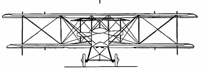
 Of the devices suggested [for man to fly] many showed ingenuity; and some were quaint, in view of ...") Besnier’s Apparatus
Besnier’s Apparatus
Of the devices suggested [for man to fly] many showed ingenuity; and some were quaint, in view of what we know of flight to-day. In the machine, for instance, designed by an experimenter named Besnier—who was a locksmith by trade—there were four lifting planes, closing on the up-stroke and opening on the down, and these the operator was to flap by the use of his hands and feet. Of the doings of another of these brave but reckless men—a Saracen who tried to fly in the twelfth...") First attempts
First attempts
Of the doings of another of these brave but reckless men—a Saracen who tried to fly in the twelfth century—there is fuller information. He provided himself with wings which he stiffened with wooden rods, and held out upon either side of his body. Wearing these, he mounted to the top of a tower in Constantinople and stood waiting for a favourable gust of wind. When this came and caught his wings, he “rose into the air like a bird.” And then, of course, seeing that he had no idea of balancing himself when actually aloft, he fell pell-mell and “broke his bones.” People who had gathered to watch, seeing this inglorious ending to the flight, burst into laughter: ridicule rather than praise, indeed, was the fate of the pioneers, even to the days when the first real flights were made. (649 visits) Their first glider was a biplane, with 165 square feet of lifting surface, as illustrated in figure;...") The 1900 Wright Glider (operator’s position)
The 1900 Wright Glider (operator’s position)
Their first glider was a biplane, with 165 square feet of lifting surface, as illustrated in figure; several of its features need explanation. First there is the position of the operator; he can be seen lying prone across the centre of the lower plane. This attitude was adopted by the Wrights to minimise wind-pressure. Should a man be upright in his machine, they calculated that his body would, as the glider passed through the air, offer an appreciable resistance; while, in lying flat, he would offer scarcely any resistance at all. In the launching of gliders, some French experimenters showed ingenuity. The brothers Voisin, for in...") Voisin Glider towed by a motor-car
Voisin Glider towed by a motor-car
In the launching of gliders, some French experimenters showed ingenuity. The brothers Voisin, for instance, who played a prominent part in the early tests in France, adopted the plan illustrated. The gilder was towed by a motor-car across an open stretch of ground; then, when its speed was sufficient for the planes to lift, it rose and flew behind the car like a kite. A.A.—Main-planes; B. Double front elevator; C. Rudder (two narrow vertical planes); D. Motor; E. P...") The Wright Biplane
The Wright Biplane
A.A.—Main-planes; B. Double front elevator; C. Rudder (two narrow vertical planes); D. Motor; E. Propellers; F. Pilot’s lever; G. Skids upon which machine landed. It is now possible to describe, as a completed craft, the Wright power-driven plane; The picture shows its appearance; and in looking at it one is struck by the fact that, save for one or two modifications, and the fitting of motor and propellers, the machine is practically a glider, such as the Wrights used for soaring tests. Of the changes to be observed, the most interesting concern the elevator and rear-rudder. The former, it will be seen, has a double plane; it is, in fact, a smaller biplane on the principle of the main-planes. Needing to increase the surface of the elevator, the brothers fixed one plane above another so as to make the construction stronger and occupy less space. The rear-rudder, acting like that of a ship. A. Biplane; B. Rail; C. Rope passing from the aeroplane round the pulley-wheel (D.) and thence to th...") Wright Launching Rail
Wright Launching Rail
A. Biplane; B. Rail; C. Rope passing from the aeroplane round the pulley-wheel (D.) and thence to the derrick (E.); (F.) Falling weight. Details of propulsion and control being arranged, there remained the question of how the machine should be launched into the air. In their gliding tests, it will be remembered, the Wrights employed assistants, who held the machine by the wing-tips and ran forward with it. But the weight of the power-driven machine, and its greater size, prevented such a plan as this. They decided, therefore, to launch it from a rail, and to aid its forward speed, at the moment of taking the air, by a derrick and a falling weight. A form of glider, mounted upon hollow wooden floats—anticipating the sea-plane of to-day—and tow...") Voisin Glider on the river Seine
Voisin Glider on the river Seine
A form of glider, mounted upon hollow wooden floats—anticipating the sea-plane of to-day—and towed upon the river Seine by a motor-boat. This gilder also, when its speed became sufficient, rose into the air. In the construction of the machine, a biplane, one notes resemblances to the method of the Wrights; and yet generally the craft is dissimilar. Two assistants took the machine by its plane-ends and ran forward with it, the pilot assuming before...") Launching the Wright Glider
Launching the Wright Glider
Two assistants took the machine by its plane-ends and ran forward with it, the pilot assuming beforehand his position upon the plane; then, when they had gained a pace sufficient for the machine to soar, they released their hold and it glided forward. Beneath the glider, under the centre of the lower plane, there were two wooden skates or runners, and these took the weight of the machine when it alighted, and allowed it to slide forward across the ground before coming to rest. By the use of these landing skids, and by steering at as fine an angle as possible, the Wrights found they could touch ground, even at 20 miles an hour and lying across the machine, without injury either to themselves or the craft. Now, patient and assiduous, he (Lilienthal) began to teach himself the art of aerial balance. Raisin...") Lilienthal gliding
Lilienthal gliding
Now, patient and assiduous, he (Lilienthal) began to teach himself the art of aerial balance. Raising his wings to his shoulders he would face the wind—which in his first tests he did not care to be blowing at more than ten or fifteen miles an hour. Then, running against the wind to increase the pressure beneath his wings, he would raise his legs and begin to glide, moving forward and at the same time downward. How he appeared when in flight is indicated by the picture. showing the shape of wings and tail, and the positions of the pilot and passenger within the hull.
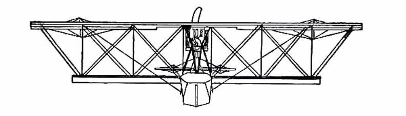
...") A Flying Boat top view
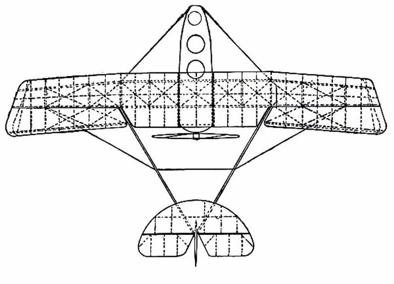
A Flying Boat top view
showing the shape of wings and tail, and the positions of the pilot and passenger within the hull.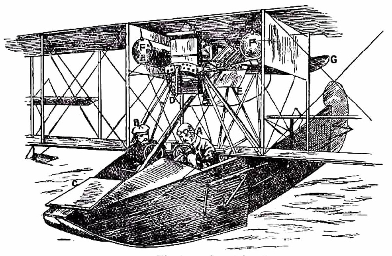
 By the use of such a machine as this, twenty years hence, we shall be able to spend a week-end in Ne...") Airliners of the future
Airliners of the future
By the use of such a machine as this, twenty years hence, we shall be able to spend a week-end in New York, as we do now in Paris or Scotland. Flying at immense heights, and at speeds of 200 miles an hour, these huge aircraft—carrying hundreds of passengers in vibrationless luxury—will pass from London to New York in less than twenty hours. (Early Type)
A. Elevating-plane
B. Seats for pilot and passenger
C. Main-planes
D. Motor with...") Maurice Farman Biplane
Maurice Farman Biplane
(Early Type) A. Elevating-plane B. Seats for pilot and passenger C. Main-planes D. Motor with two-bladed propeller E. Vertical panel F. Aileron G. Tail-planes H. Rudders I. Landing chassis. Apart from governing the ascending or descending movement, there was the question of preventing a ma...") The Wright Wing-warp
The Wright Wing-warp
Apart from governing the ascending or descending movement, there was the question of preventing a machine from slipping sideways; and this the Wrights solved ingeniously. They saw, of course, that when their glider lurched to one side or the other, they would need some power to tilt it back again. So they devised a system by which the plane-ends of their machine—being made flexible—might be warped, or caused to shift up and down. This action the operator controlled, as he lay across the lower plane, by a movement of cords, and its operation is shown in Figure. The effect upon the machine may be described thus: should a wind-gust tilt down one plane-end, the “warp” upon that side of the machine was drawn down also, and the effect of this—seeing that it caused the plane to assume a steeper angle to the air and exercise a greater lift—was to raise the plane-ends that had been driven down by the gust. By a system of connecting the control cords, this balancing influence was made to act with double force; when one wing warped down, the other moved up; and, in this way, while the side of the machine tilted down was made to rise, the other plane-ends, which had been lifted, were made to descend. A dual righting influence was thus obtained. This system, which imitates the flexing movements made by a bird, was an important device; the Wrights patented it—combining the movement with an action of the rudder—and brought cases at law to enforce their rights. In the picture the operator is seen in the driving seat; and near him will be observed the motor whi...") Driving seat of Wright Biplane
Driving seat of Wright Biplane
In the picture the operator is seen in the driving seat; and near him will be observed the motor which drives the craft. In his left hand—that is to say in the one nearest us—he grasps the lever which operates the elevating planes. The rod from lever to plane can be seen, and the motions the pilot makes are these: should he wish to rise, he draws the lever towards him and tilts up the elevating planes in the manner already described, increasing the lifting power of the main-planes and so causing the machine to ascend; by a reverse movement of the lever—by pushing it away from him, that is to say—he makes the craft glide downward. Another machine which is stable in flight, owing to the peculiar formation of its wings, which resis...") Dunne inherently stable Biplane
Dunne inherently stable Biplane
Another machine which is stable in flight, owing to the peculiar formation of its wings, which resist a diving or plunging movement, or a lateral swing, is the Dunne biplane—as designed by Lieutenant J. W. Dunne. This craft is seen in the figure. Using such a machine, pilots have flown for long distances with the control levers locked, the biplane adapting itself automatically to the wind-gusts and preserving its equilibrium without aid of any kind. It has neither fore-plane nor tail; it is made to ascend by elevators which are in the form of hinged flaps, or ailerons, and is steered by two rudders at the extremities of the main-planes. A. Hull containing pilot and passenger B.B. Main-planes C.C.C.C. Flaps used as elevators D.D. Side-planes which act as rudders E. Engine and propeller F. Alighting gear. The difficulty with air-cooling—although it had obvious advantages over water-cooling—was to bri...") The seven-cylinder 50-h.p. Gnome motor.
The seven-cylinder 50-h.p. Gnome motor.
The difficulty with air-cooling—although it had obvious advantages over water-cooling—was to bring enough air to play upon the surfaces of the cylinders; and it was here that the Gnome won so complete a success. In other engines the cylinders were stationary, and their pistons, moving up and down in the cylinders, turned a crank-shaft to the end of which the propeller was fixed. Therefore the only air the cylinders obtained was what rushed upon them through the speed of the machine in flight. But in the Gnome, instead of the cylinders remaining stationary and the crank-shaft revolving, the cylinders themselves spun round, and the crank-shaft did not move. An illustration of this motor with one end of the crank-chamber removed, so that the piston-rods can be seen, is given in the figure. It will be noted that there are seven cylinders, set in the form of a star, and that the seven piston-rods projecting from them come together upon a single crank-pin, which is attached to the stationary crank-shaft and turns round it. The propeller, instead of being fitted to the crank-shaft, as was the case with other motors, was bolted to a plate upon the engine itself, so that when this turned around its crank-shaft, it carried the propeller with it. Drasina
This novel vehicle, under the name of \" Drasina was introduced into England in 1818, and, a...") Drasina
Drasina
Drasina This novel vehicle, under the name of " Drasina was introduced into England in 1818, and, at first, the greatest possible expectations were created, with regard to its usefulness and speed. It was maintained, that it would travel up-hill on a post-road as fast as a man could walk ; that on a level, even after a heavy rain, it would average six or seven miles an hour ; and that, on a descent, it would equal a horse at fall speed. It was described in the advertisements of the day as " consisting of two wheels, one behind the other, connected by a perch, on which a saddle is placed as a seat. The front wheel is made to turn on a pivot, guided by a circular lever or rudder, which comes op to the hand; the fore-arms rest on a cushion in front ; in this position, both hands holding the rudder firmly, the machine and traveller are preserved in equilibrio. In 1821 Lewis Gomperta of Surrey, introduced some decided improvements upon the Drasina , as will be seen from the accompanying engraving. The object of the improvement of Gomperta was to bring the arms of the rider into action, in assist-ance to his legs. It consisted " in the application of a handle, C, which is to be worked backwards and forwards, to which is attached a circular rack, D G, which works in a pinion, E, with ratch wheel on the ont wheel of the velocipede, and which, on being pulled by the rider with both hands, sends the machine forward; and when thrust from him does not send it back again, on account of the ratch, which allows the pinion to turn in that direction, free of the wheel. H is the saddle, and the rest, B is so made that the breast of the rider bears against it, while the sides come around him at some distance below the arms, and is stuffed." The rider could with this machine either propel it entirely without the feet, or he could use the feet, while the arms were free. The beam, A, was made of beech wood, and a pivot at F, allowed the front wheel to be turned to the right or left at the will of the rider. showing the span of the main-planes, and the curve of the boat-shaped hull.") A Flying Boat
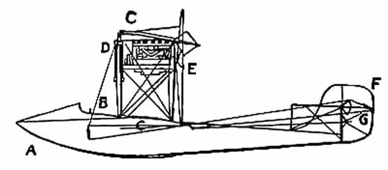
A Flying Boat
showing the span of the main-planes, and the curve of the boat-shaped hull.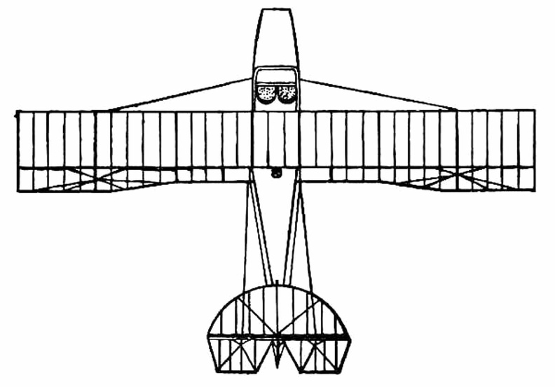
 Ader next turned to steam-driven craft, and built a series of queer, bat-like machines, which he cal...") Ader’s 'Avion'
Ader’s 'Avion'
Ader next turned to steam-driven craft, and built a series of queer, bat-like machines, which he called “Avions,” one of which is illustrated in Fig. 16. Its wings were built up lightly and with great strength by means of hollow wooden spars, and had a span of 54 feet, being deeply arched. The whole machine weighed 1100 lbs., and was thus far smaller and lighter than Maxim’s mighty craft. To propel it, Ader used a couple of horizontal, compound steam engines, which gave 20 h.p. each and drew the machine through the air by means of two 4-bladed screws. The craft was controlled by altering the inclination of its wings, and also by a rudder, the pilot sitting in a carriage below the planes. In 1890, after its inventor had spent a large sum of money, the machine—which, unlike those of Phillips and Maxim, ran upon wheels and was free to rise—did actually make a flight, or rather a leap into the air, covering a distance of about fifty yards. But then, on coming into contact with the ground again, it was wrecked. Ader’s experiments were regarded by the French Government as being so important that he received a grant equalling £20,000 to assist him in continuing his tests; and this goes to show how, even from the first, the French nation was—by reason of its enthusiasm and imagination—able to appreciate what its inventors were striving to attain, and eager to encourage them in their quest. It was not until 1906, at a time when the Wright aeroplane was capable of long flights, that a real ...") Santos-Dumont’s Biplane which flew at Bagetelle
Santos-Dumont’s Biplane which flew at Bagetelle
It was not until 1906, at a time when the Wright aeroplane was capable of long flights, that a real French success was obtained; and then the flights made were brief, and carried out with a craft that was admittedly crude. It was a biplane of curious construction, built by the Voisin brothers for M. Santos-Dumont—a rich Brazilian who had spent money freely upon airships, and had been occupied, for some time before the Voisins made him this machine, with a craft having propellers to lift it vertically from the ground. Abandoning this idea, he devoted himself to the machine the Voisins built, which is seen in the picture. A. Pilot’s seat and controlling wheel
B. Passenger’s seat
C. Movable flap to facilitate enteri...") The hull of a Flying-Boat
The hull of a Flying-Boat
A. Pilot’s seat and controlling wheel B. Passenger’s seat C. Movable flap to facilitate entering the hull D. Handle, like that of a car, for starting the engine E. The engine F. Fuel tanks G. The propeller.
 England, in the building and handling of sea-planes has come well to the fore, and our machines are ...") A Bleriot Sea-plane
A Bleriot Sea-plane
England, in the building and handling of sea-planes has come well to the fore, and our machines are more advanced than those of other countries. The Admiralty has recognised that, acting as a coastal scout in time of war, such craft would be of the utmost value; thus we find air-stations dotted round our seaboard, from which machines may fly in a regular patrol. By the employment of hundreds of craft, operating upon a well-ordered plan, it will be possible in the future to girdle our shores completely; and such machines would not only spy out the approach of an enemy’s fleet, but give battle to hostile aeroplanes or airships which might seek to pass inland. The type of machine we have just described was a biplane, but there are monoplane sea-craft, and a Bleriot fitted for alighting upon the water is shown.") Yale 1910
Yale 1910 (866 visits)") Parts of a motorbike (2)
Parts of a motorbike (2) A.A. Ballast bags filled with sand
B. Instruments (such as a statoscope, which shows at any moment ...") The car of a modern Balloon
The car of a modern Balloon
A.A. Ballast bags filled with sand B. Instruments (such as a statoscope, which shows at any moment whether the balloon is rising or falling; and an altitude meter) C. Ring by which car is attached to balloon. Fast mail-carrying aeroplanes will make postal deliveries everywhere") Fast mail-carrying aeroplanes will make postal deliveries everywhere
Fast mail-carrying aeroplanes will make postal deliveries everywhere
Fast mail-carrying aeroplanes will make postal deliveries everywhere The sea-plane, when a flight is made, is launched upon the water down a slipway; then the pilot and ...") An Avro Sea-Plane
An Avro Sea-Plane
The sea-plane, when a flight is made, is launched upon the water down a slipway; then the pilot and his passenger embark, the motor is started, and the propeller draws the machine across the water at a rapidly increasing pace. The floats raise themselves higher and higher upon the water, as the air-planes exercise a growing lift, until they only just skim the surface. And now comes the moment when the airman, drawing back his elevating lever, seeks to raise his craft from the water into the air. At first only the front of the floats rise, the rear sections clinging to the surface; then, in another instant, the whole float frees itself from the water in a scatter of spray, and the craft glides at a gently-sloping angle into the air. It is the aim of builders, by the curve they impart, to make the floats leave the water with as little resistance as possible. In the floats of the Avro will be noticed a notch, or cut-away section, which occurs at about the centre of the float upon its lower side. This is called a “step,” and is to help the float to lift from the water. When the main-planes draw upward, as the craft moves prior to its flight, the floats tend, as has been said, to raise themselves in the water; and as they do so, lifting first towards the bow, there comes a space between the upward-cut “step” and the surface of the water. Into this space air finds its way and, by helping still further to free the float from the surface, aids greatly at the moment when the pilot—operating his hand-lever—seeks the final lift which will carry him aloft. A. Propeller B. 100-h.p. Gnome motor, hidden by shield C. Main-planes D. Observer’s seat E. Pilot’s seat F. Rudder G. Elevating-plane H. Float to support tail I. Main floats to bear the weight of the machine. “Looping the loop,” which has made so great a sensation, has taught airmen one definite lesson; ...") Looping the loop
Looping the loop
“Looping the loop,” which has made so great a sensation, has taught airmen one definite lesson; and it is this: no matter how their machines may be beaten and tossed by the wind, they need not fear a fall—provided they are high enough above ground. The movements of a machine, as it makes a series of “loops,” are shown in the figure. The pilot reaches a high speed before he rears up his machine to begin the “loop,” and this downward velocity is attained by diving; then, when he estimates his pace sufficient, he pulls his elevating-lever back and the machine leaps upward, rearing itself vertically towards the sky, turning over on its back, then diving again and coming right-side-up—thus achieving a complete somersault. A skilled trick-flyer, also, will allow his machine to drop sideways or tail first, deliberately working the controls so that it shall do so. Then, just as it seems to spectators that he is falling to destruction, he will dive or twist, regain the mastery of his machine, and descend in a normal glide.") Parts of a motorbike
Parts of a motorbike") 1910 Curtis
1910 Curtis Of the various kinds of velocipedes, four, three, two, and one wheeled, the bicycle seems to be cons...") The Bicycle
The Bicycle
Of the various kinds of velocipedes, four, three, two, and one wheeled, the bicycle seems to be considered the most artistic, is altogether the most in favor, and steadily maintains its ground against all rivals. Whether it will be the model velocipede of the future remains to be seen. The various experiments now being tried will, no doubt, eventually result in a nearly perfect machine, but it will require a season's experience fully to develop the ingenuity of our American artisans. Many have expressed doubts as to the real utility of the velocipede, and the permanency of its use. They seem to think it a frivolous invention only calculated to serve purposes of amusement, and soon to be superseded by some other ephemeral claimant for popularity. Most of these have based their opinions upon the disuse into which rude machines have fallen in former times. But the difference in the construction of the modern velocipede from the primitive one has entirely changed the character of the vehicle. It is no longer a draft vehicle, but a locomotive, and as much superior to the original bar on wheels, as the improved steam locomotive is to the old-time stage-coach. An Airship leaving its shed
A. The machine emerging stern first
B. A sister craft in dock
C. Th...") An Airship leaving its shed
An Airship leaving its shed
An Airship leaving its shed A. The machine emerging stern first B. A sister craft in dock C. The launching crews D. Rails upon which the cars of the airship move, so as to prevent its swinging sideways in a gust E. Outlook station upon the roof of the shed F. Workshops; living quarters for the crews; plant for making hydrogen gas.") Sidecar
Sidecar") 1910 New Engines
1910 New Engines A. Hull
B. seats for crew
C. Planes
D. Motor
E. Propeller
F. Rudder
G. Elevators.
...") A Flying Boat - side view
A Flying Boat - side view
A. Hull B. seats for crew C. Planes D. Motor E. Propeller F. Rudder G. Elevators.
 An experimenter who braved this apathy and won his way until he became a constructor of aircraft, wa...") The Roe Triplane
The Roe Triplane
An experimenter who braved this apathy and won his way until he became a constructor of aircraft, was Mr. A. V. Roe. For some time he was an advocate of the triplane form of machine—a craft, that is to say, with three main-planes fitted one above another. The machine with which he obtained flights, although they were very brief, is seen in the figure. Subsequently, however, Mr. Roe adopted the biplane form. His distinction in the pioneer days was that he managed to make his triplane lift into the air and fly a short distance, with the aid of a motor-cycle engine developing no more than 9 h.p. A.A.A. Three main-planes B. Motor C. Four-bladed propeller D.D.D. Triplane tail E. Rudder F. Landing gear. Ship saved by life line thrown from a rescue airship
[Not sure what it did to save the boat]") Ship saved by life line thrown from a rescue airship
Ship saved by life line thrown from a rescue airship
Ship saved by life line thrown from a rescue airship [Not sure what it did to save the boat] A. Wheels operating elevating-planes and rudder
B. Height recorder
C. Speaking-tube to communicate...") Control platform of an Airship
Control platform of an Airship
A. Wheels operating elevating-planes and rudder B. Height recorder C. Speaking-tube to communicate with engineers. A machine that has achieved success, owing to its power of varying speed, is the Sopwith military bi...") Sopwith Military Biplane
Sopwith Military Biplane
A machine that has achieved success, owing to its power of varying speed, is the Sopwith military biplane. Adopting a practice that has become general, its wings are fitted upon what is practically a monoplane body. Tail-planes and rudder are the same as in a monoplane. The top main-plane, as will be seen, is set slightly in advance of the lower. The system is called “staggering”; and the idea is that, by placing the upper plane ahead of the lower, the total lifting power will be increased. It has been proved a disadvantage of the biplane that, when the main-planes are placed one above another, there is a slight loss of lift owing to the fact that, acting upon the air as they do quite close to each other, a certain amount of interference occurs between them—one tending to disturb the air-stream in which the other moves. By “staggering” the two planes this interference is overcome; but some makers regard it as a small consideration, and build their planes in the ordinary way, allowing as large a gap as possible between them. In the Sopwith military machine, engine and propeller are in front of the main-planes; then come the places for pilot and observer. The pilot sits first, and the body of the machine is so high that only his head appears above it, while just in front of his face, to deflect the wind-rush from the propeller, there is a raised section of the hull which acts as a screen. Behind the pilot, sitting in a second opening in the hull, is the observer. He has a view forward, rendered the better by setting back the lower-plane; while at the point at which it joins the body of the machine, immediately below him, this plane is hollowed out, so that he can look directly upon the earth below. Small windows are also fitted upon either side of the hull. Through those in front the pilot may glance when descending from a flight, so as to judge his distance from the ground, while the others are utilised by the observer, as he turns to look from side to side. This biplane, and many others, is balanced against sideway roll by ailerons, and not by warping the wings. Constant warping, such as is necessary in the everyday use of machines, has been declared to strain a plane and render it weak; therefore the use of ailerons is now favoured. A. Propeller B. Motor, partly hidden by shield C.C. Main-planes D. Pilot’s seat E. Observer’s seat F. Outlook windows in side of hull G. Rudder H. Elevating-plane I. Landing gear. A typical craft, representing the first of those navigated with any certainty, is shown in Figure. A...") Early-type Airship
Early-type Airship
A typical craft, representing the first of those navigated with any certainty, is shown in Figure. A gas-containing envelope, made of a light, strong, varnished fabric, is kept taut by the pressure of the gas within; the car, constructed of wood or metal tubing, is suspended by ropes from the envelope, and contains engine and crew, with a two-bladed propeller revolving astern. Such a machine, in its control, had an elevating-plane and rudder, upon the same principle as those of the aeroplane. One of the difficulties to be overcome was the expansion and contraction of gas in the envelope owing to differences in altitude and temperature. When the craft ascended, its envelope completely inflated, the gas began to dilate owing to the outer air becoming less dense; and some had to be allowed to escape through automatic valves. Then, should the machine descend to a lower level, there was not sufficient gas in the envelope to keep it tightly stretched, and it tended to sag at the bow as it was driven through the air. A. Gas envelope B. Car suspended below envelope C. Motor, which drives propeller (D) through a shaft E. Small horizontal plane for rising or descending F. Fixed fin, or keel plane, to give stability G. Rudder.") Revenue Cutter
Revenue Cutter Whistling bouy
Less picturesque than lighthouses and lightships, and with far less of human inter...") Whistling bouy
Whistling bouy
Whistling bouy Less picturesque than lighthouses and lightships, and with far less of human interest about them, are the buoys of various sorts of which the Lighthouse Board has more than one thousand in place, and under constant supervision. Yet, among the sailor's safeguards, they `rank` near the head. They point out for him the tortuous pathway into different harbors; with clanging bell or dismal whistle, they warn him away from menacing shallows and sunken wrecks. The resources of science and inventive genius have been drawn upon to devise ways for making them more effective. At night they shine with electric lights fed from a submarine cable, or with steady gas drawn from a reservoir that needs refilling only three or four times a year. If sound is to be trusted rather than light, recourse is had to a bell-buoy which tolls mournfully as the waves toss it about above the danger spot, or to a whistling buoy which toots unceasingly a locomotive whistle, with air compressed by the Page 355action of the waves. The whistling buoy is the giant of his family, for the necessity for providing a heavy charge of compressed air compels the attachment to the buoy of a tube thirty-two feet or more deep, which reaches straight down into the water. The sea rising and falling in this, as the buoy tosses on the waves, acts as a sort of piston, driving out the air through the whistle, as the water rises, admitting more air as it falls. By another method, shown in figure, the sea-plane is launched from a cable suspended between two mas...") Launching a sea-plane from a wire
Launching a sea-plane from a wire
By another method, shown in figure, the sea-plane is launched from a cable suspended between two masts, and can come to rest upon the cable again after a flight has been made. The machine is hung upon the cable prior to making an ascent; then the pilot starts his engine, and as his machine glides forward along the cable he releases a catch and soars into the air. Upon returning he flies beneath the cable, and makes his craft rise until the “V”-shaped apparatus above his head is caught by the cable and the catch becomes operative; then he stops his motor, and his craft hangs from the cable as it did before. A. Sea-plane B. Cable C. The “V”-shaped apparatus which guides the cable into the clip (D.) and so suspends the machine from the wire.") LA Motordrome
LA Motordrome