


 The sea-plane, when a flight is made, is launched upon the water down a slipway; then the pilot and ...") An Avro Sea-Plane
An Avro Sea-Plane
The sea-plane, when a flight is made, is launched upon the water down a slipway; then the pilot and his passenger embark, the motor is started, and the propeller draws the machine across the water at a rapidly increasing pace. The floats raise themselves higher and higher upon the water, as the air-planes exercise a growing lift, until they only just skim the surface. And now comes the moment when the airman, drawing back his elevating lever, seeks to raise his craft from the water into the air. At first only the front of the floats rise, the rear sections clinging to the surface; then, in another instant, the whole float frees itself from the water in a scatter of spray, and the craft glides at a gently-sloping angle into the air. It is the aim of builders, by the curve they impart, to make the floats leave the water with as little resistance as possible. In the floats of the Avro will be noticed a notch, or cut-away section, which occurs at about the centre of the float upon its lower side. This is called a “step,” and is to help the float to lift from the water. When the main-planes draw upward, as the craft moves prior to its flight, the floats tend, as has been said, to raise themselves in the water; and as they do so, lifting first towards the bow, there comes a space between the upward-cut “step” and the surface of the water. Into this space air finds its way and, by helping still further to free the float from the surface, aids greatly at the moment when the pilot—operating his hand-lever—seeks the final lift which will carry him aloft. A. Propeller B. 100-h.p. Gnome motor, hidden by shield C. Main-planes D. Observer’s seat E. Pilot’s seat F. Rudder G. Elevating-plane H. Float to support tail I. Main floats to bear the weight of the machine. An Airship leaving its shed
A. The machine emerging stern first
B. A sister craft in dock
C. Th...") An Airship leaving its shed
An Airship leaving its shed
An Airship leaving its shed A. The machine emerging stern first B. A sister craft in dock C. The launching crews D. Rails upon which the cars of the airship move, so as to prevent its swinging sideways in a gust E. Outlook station upon the roof of the shed F. Workshops; living quarters for the crews; plant for making hydrogen gas. Airships, like aeroplanes, are being armed with guns and bombs; and their power of raising weights e...") Aeroplanes attacking an airship from above
Aeroplanes attacking an airship from above
Airships, like aeroplanes, are being armed with guns and bombs; and their power of raising weights enables them to carry heavy weapons. Large and highly destructive bombs have been tested in the German airships, being released over the sea and aimed at targets in the form of rafts. Latest-type airships also carry guns in their cars; and the Zeppelins have a platform upon the tops of their hulls, reached by a ladder through the middle of the ship, from which a machine-gun can be fired upward. This is a very necessary precaution, and is intended to frustrate the attack of an aeroplane. It would be the aim of the latter, whenever possible, to manœuvre above its big enemy—as suggested in figure —and drop a bomb upon its hull. Hence the construction of the top platform of the airship, from which her gunners can direct a vigorous fire aloft. Air-racing, as made popular by the proprietors of the Hendon aerodrome, forms so fascinating a sight...") A pylon, or mark-tower, on the flying track
A pylon, or mark-tower, on the flying track
Air-racing, as made popular by the proprietors of the Hendon aerodrome, forms so fascinating a sight that, on a day of public holiday, as many as 50,000 people will assemble in the enclosures. To stand near one of the pylons—wooden towers which mark the turning-points of the course—and see the air-racers come rushing by, is to gain such an impression of speed as almost makes the watcher hold his breath. The pilot in a flying race has one chief aim: to fly the shortest way. Every fraction of a second is of importance; and if he can circle the pylons more skilfully than his rivals, he may win the race, even though his machine—in its actual speed—may be no faster than theirs. We present a bicycle for ladies, lately invented and patented by Messrs. Pickering & Davis of New Yo...") Velocipede for Ladies
Velocipede for Ladies
We present a bicycle for ladies, lately invented and patented by Messrs. Pickering & Davis of New York City. It will be seen that the reach or frame, instead of forming a nearly straight line from the front swivel to the hind axle, follows the curve of the front wheel until it reaches a line nearly as low as the hind axle when it runs horizontally to that point of the hind wheel. The two wheels being separated three or four inches, allow of an upright rod being secured to the reach; around this is a spiral spring, on which a comfortable, cane-seated, willow-backed chair is placed. This machine, with a moderate-sized wheel (of thirty to thirty-three inches), will allow being driven with a great deal of comfort and all the advantages of the two-wheel veloce. In mounting, a lady has to step over the reach, at a point only twelve inches from the floor, the height of an ordinary step in a flight of stairs. We present an engraving of an English one-wheeled velocipede. The feet are placed on short stilts, c...") English one-wheeled Velocipede
English one-wheeled Velocipede
We present an engraving of an English one-wheeled velocipede. The feet are placed on short stilts, connected with the cranks, one on either side of the rim, while the rider sits upon a steel spring saddle over the whole wheel. The inventor modestly limits the diameter of the wheel to twelve feet, and the number of revolutions to fifty per minute. Twenty-five miles per hour is the speed expected to be reached. The riders of this machine, without the ability to overcome the laws of gravity, would be very likely to get broken bones and noses. It is not likely to come into general use. HEMMING'S UNICYCLE, or \"FLYING YANKEE VELOCIPEDE.\"
The single-wheeled velocipede has at length ...") Flying Yankee Velocipede
Flying Yankee Velocipede
HEMMING'S UNICYCLE, or "FLYING YANKEE VELOCIPEDE." The single-wheeled velocipede has at length received a palpable body, and " a local habitation and a name." Richard C. Hemming of New Haven, Conn., invented the machine herewith represented, two years ago; but has only recently brought it into the market and applied it to practical purposes.. The main wheel has a double rim, or has two concentric rims, the inner face of the inner one having a projecting lip for keeping the friction rollers and the friction driver in place; each of these being correspondingly grooved on their peripheries. The frame on which the rider sits, sustains these friction wheels in double parallel arms, on the front one of which is mounted a double pulley, with belts passing to small pulleys on the axis of the driving wheel. This double wheel driven, as seen, by cranks turned by the hands. The friction of the lower wheel on the surface of the inner rim of the main wheel is the immediate means of propulsion. A small binding wheel, seen between the rider's legs, serves to keep the bands or belts tight. The steering is effected either by inclining the body to one side or the other, or by the foot impinging on the ground, the stirrups being hung low for this purpose. By throwing the weight on these stirrups, the binding wheel may be brought more powerfully down on the belts. Over the rider's head is an awning, and there is also a shield in front of his body to keep the clothes from being soiled by mud and wet. When going forward, the driving wheel is kept slightly forward of the centre of gravity by the position of the rider. By this means the power exerted is comparatively small. Every turn of the crank is equivalent to a rotation of the great wheel. Mr. Hemming says that this machine can be manufactured for fifty dollars, of a weight of only thirty pounds;- that it will ascend steep grades, and that it can be driven on the roads with but little exertion, at the rate of twenty or even twenty-five miles an hour. This wheel is of a diameter of from six to eight feet. Mr. Hemming's boy of thirteen has one five feet in diameter, the first manufactured, crude in construction, and heavier than necessary, which he propels at the rate of a mile in three minutes.
This velocipede was patented January 5th, 1869. It has been thoroughly tested and is pronounced a ...") Callihan's Velocipede
Callihan's Velocipede
This velocipede was patented January 5th, 1869. It has been thoroughly tested and is pronounced a complete success. It will be seen that it is very different from Bradford's machine. The front wheels are used as guiding wheels, the rear as the driving ones. It is propelled by both hands and feet, acting together or separately. The propelling power is almost unlimited, and is furnished by cranks in the hind axles, with lever attachments. It has three different steering arrangements, either of which can be applied, according to the taste of the purchaser. In all these, the forward wheel and axle are turned with a lever arrangement, operated upon by the band. The machine develops both chest and limbs, and can be readily used by ladies and children. A little girl of six years has ridden it for an hour without fatigue. It is so constructed, that scruples of delicacy need prevent no lady from driving it. It can be driven either backwards or forwards, will run upon the road, at the rate of fifteen miles an hour, and will ascend any ordinary hill with ease. It is claimed, that it is the only machine made that can be checked in going down hill, or that can be stopped instantly. The machine varies in size and weight. That most in favor, has a wheel of three feet and a half in diameter, and a weight of about one hundred pounds. It is constructed of the best material, and is neat and nobby in appearance. Its price is $125. If any of our readers desire the luxury of a ride on a velocipede without the necessity of taking le...") Bradford's Velocipede
Bradford's Velocipede
If any of our readers desire the luxury of a ride on a velocipede without the necessity of taking lessons, or the danger of getting a fall, they will find " Bradford's Four-Wheeled Velocipede" ready and able to afford them the pleasure. The inventor of this vehicle, Mr. C. K. Bradford, has devoted the greater part of the last five years to experiments upon the velocipede, and took out his first patent three years and a half ago. The machine, as now constructed and improved, obtained its American patent October 13th, 1868. It has since been patented in England, France, and Belgium. It is made of the best material, and finished like a gentleman's trotting wagon. It weighs but sixty-five pounds, and combines in a high degree both lightness and strength. Any man, woman or child, can learn to guide it easily with but a few moments practice. The inventor claims that it is able to maintain a speed of a mile in three minutes, and that the extraordinary time of a half mile in one minute and forty-five seconds, has been made upon a country road. It can be driven by almost any man, at the rate of a mile in four minutes, on almost any road, without greater exertion than is ordinarily used in walking. This velocipede, unlike all others, is seen to best advantage on the street. In Mr. Bradford's tasteful little curricle, the rider can sit at ease as carelessly as in a carriage, giving himself up wholly to the exhilaration of the rapid movement, and the pleasurable exercise of the muscles, which is just enough to make the machine skim over the ground, and give an enjoyable sense of power. The increase of friction, which would naturally result from the additional number of wheels, is prevented by an application of anti-friction rollers, which reduce the labor of propelling the machine to a minimum, a requisite of the highest importance to a person seeking either recreation or utility. As will be seen from the accompanying engraving, \"Pickering's American Velocipede,\" manufactured by ...") Pickering's American Velocipede
Pickering's American Velocipede
As will be seen from the accompanying engraving, "Pickering's American Velocipede," manufactured by Messrs. Pickering & Davis, differs very materially from the French model, so generally used by other manufacturers. It is claimed that it is more simple and durable, lighter and stronger. The reach or frame of this velocipede is made of hydraulic tubing. The gun-metal bearings are so attached that, when worn, they may be replaced by others, which are interchangeable like the parts of sewing-machines and fire-arms. The axle is so constructed as to constitute, in itself, an oil box. It is made tubular, and closed at either end with a screw, on the removal of which it is filled with lard oil. Cotton lamp-wick is placed loosely in the tubular axle and the oil is by this means fed to the bearing, as fast as required, through the small holes made for the purpose in the centre of the axle. The saddle is supported on a spiral spring, giving an elastic seat; it is brought well back, so that the rider maintains an erect position, and is adjustable to suit the length of limb of the rider. The tiller or steering handle is constructed with a spring so that the hands are relieved from the jolting that they would otherwise receive while running over rough ground. The stirrups or crank pedals, are three-sided, with circular flanges at each end, fitted to turn on the crank pins, so that the pressure of the foot will always bring one of the three sides into proper position. They are so shaped as to allow of the use of the forepart of the foot, bringing the ankle joint into play, relieving the knee, and rendering propulsion easier than when the shank of the foot alone is used. The connecting apparatus differs from that of the French vehicle in that the saddle bar serves only as a seat and brake, and is not attached to the rear wheel. By a simple pressure forward against the tiller, and a backward pressure against the tail of the saddle, the saddle spring is compressed, and the brake attached to it brought firmly down against the wheel. Messrs. Pickering & Davis have a large manufactory, and are the constant recipients of orders from all parts of the country. Mr. Pickering has always been a practical machinist, and personally superintends the structure of each machine turned out.
The accompanying engraving will convey to the mind of the reader a correct idea of the French two-...") Construction of the Bicycle
Construction of the Bicycle
The accompanying engraving will convey to the mind of the reader a correct idea of the French two-wheeled velocipede. The majority of makers in this country fashion their machine upon this pattern in every essential respect. We append a full technical description. A is the front wheel. This is the steering wheel, and upon its axis, the power is applied. B is the hind wheel; C, the treadles or foot-pieces ; D, the treadle cranks; E, slots in cranks, by which to adjust the foot-pieces and accommodate the length to the legs of the rider; F, bifurcated jaw, the lower part of which forms the bearing for the axle of the front wheel. From the upper part of this jaw, a rod or pivot extends, to which is attached the steering arm or handle F; G, the reach or perch, extending from the jaw of the front wheel to the rear or hind wheel. This reach is bifurcated, forming jaws for the hind wheel. H, " rests" on the front part of the reach. The rider puts one leg on the rest and works one of the cranks with the other leg while riding " side-saddle," or a leg may be placed upon each rest when the velocipede has acquired sufficient momentum, and the rider does not wish to keep his feet upon the treadles. I, the saddle or seat, which is adjustable on the seat-spring L, by the thumb-screw K. The seat-spring L, is attached at M to the reach G, which, at the other end, is fastened to the spring-struts N, that rise from the reach G; 0, the brake-lever, on the fulcrum P; Q,, the " shoe " of the brake that acts against the periphery of the hind wheel. The brake is operated by means of the cord S, one end of which is attached to the steering handle F, and the other end to the reach at 3. A cord passes from the steering handle under the pulley or roller 4, thence over the pulley 5, on the brake-lever 0, and from there to the point 3, where it is attached to the reach G. The brake is operated by giving a slight turning motion to the handle F, thus winding a small sheave upon the axis of the handle, and bring-ing the shoe Q, of the brake-lever 0, in contact with the surface of the wheel B. Of the various kinds of velocipedes, four, three, two, and one wheeled, the bicycle seems to be cons...") The Bicycle
The Bicycle
Of the various kinds of velocipedes, four, three, two, and one wheeled, the bicycle seems to be considered the most artistic, is altogether the most in favor, and steadily maintains its ground against all rivals. Whether it will be the model velocipede of the future remains to be seen. The various experiments now being tried will, no doubt, eventually result in a nearly perfect machine, but it will require a season's experience fully to develop the ingenuity of our American artisans. Many have expressed doubts as to the real utility of the velocipede, and the permanency of its use. They seem to think it a frivolous invention only calculated to serve purposes of amusement, and soon to be superseded by some other ephemeral claimant for popularity. Most of these have based their opinions upon the disuse into which rude machines have fallen in former times. But the difference in the construction of the modern velocipede from the primitive one has entirely changed the character of the vehicle. It is no longer a draft vehicle, but a locomotive, and as much superior to the original bar on wheels, as the improved steam locomotive is to the old-time stage-coach. Drasina
This novel vehicle, under the name of \" Drasina was introduced into England in 1818, and, a...") Drasina
Drasina
Drasina This novel vehicle, under the name of " Drasina was introduced into England in 1818, and, at first, the greatest possible expectations were created, with regard to its usefulness and speed. It was maintained, that it would travel up-hill on a post-road as fast as a man could walk ; that on a level, even after a heavy rain, it would average six or seven miles an hour ; and that, on a descent, it would equal a horse at fall speed. It was described in the advertisements of the day as " consisting of two wheels, one behind the other, connected by a perch, on which a saddle is placed as a seat. The front wheel is made to turn on a pivot, guided by a circular lever or rudder, which comes op to the hand; the fore-arms rest on a cushion in front ; in this position, both hands holding the rudder firmly, the machine and traveller are preserved in equilibrio. In 1821 Lewis Gomperta of Surrey, introduced some decided improvements upon the Drasina , as will be seen from the accompanying engraving. The object of the improvement of Gomperta was to bring the arms of the rider into action, in assist-ance to his legs. It consisted " in the application of a handle, C, which is to be worked backwards and forwards, to which is attached a circular rack, D G, which works in a pinion, E, with ratch wheel on the ont wheel of the velocipede, and which, on being pulled by the rider with both hands, sends the machine forward; and when thrust from him does not send it back again, on account of the ratch, which allows the pinion to turn in that direction, free of the wheel. H is the saddle, and the rest, B is so made that the breast of the rider bears against it, while the sides come around him at some distance below the arms, and is stuffed." The rider could with this machine either propel it entirely without the feet, or he could use the feet, while the arms were free. The beam, A, was made of beech wood, and a pivot at F, allowed the front wheel to be turned to the right or left at the will of the rider. The article upon the Velocipede in the \" American Encyclopedia,\" commences by giving the well-known ...") Velocipedes
Velocipedes
The article upon the Velocipede in the " American Encyclopedia," commences by giving the well-known derivation of the word from the Latin velox, swift, and pes, a foot, and defines it as a carriage, by means of which the rider propels himself along the ground, and states that it was invented at Manheim. I will now give you a sectional division of a first-rate line-of-battle ship. Such a ship, carrying ...") Section of First-rate Man-of-War
Section of First-rate Man-of-War
I will now give you a sectional division of a first-rate line-of-battle ship. Such a ship, carrying 120 or more guns, has four decks on which her guns are placed. The highest is open to the air, and is called the UPPER DECK At the after part, extending a little way beyond the mizen-mast, there is a raised platform, called the POOP. It has no guns on it. On the main deck is the steering-wheel, with the binnacle in front of it. The after part of this deck between the poop and the main-mast is called the quarter-deck, and is the place where the officers especially walk. The part under the poop is divided into cabins, appropriated to the use of the captain. Here, also, is a clerk's office and a pantry. Between the main and fore-mast the large boats are stowed, and on either side are the gangways at which sentries are stationed. The next deck under this is called the MAIN DECK. In the after part is the admiral's cabin. Immediately under the boats is a pen for the officers' live-stock ; and just abaft the fore-mast is the galley, or kitchen. The third deck from the upper is called the MIDDLE DECK. The after part is fitted up for the lieutenants, chaplain, surgeon, paymaster, marine officers, &c., and called the WARD-ROOM. In the fore part of the deck is placed the sick-bay, a compartment fitted up as a hospital ; about the centre of this deck is one of the capstans. The fourth from the upper is called the LOWER or GUN DECK. In the after part is the GUN-ROOM, where the midshipmen, and other junior officers, mess. The tiller of the rudder works through the gun-room just above their heads. A second capstan is placed on this deck ; and forward are the riding-bitts for securing the cables. It is the lowest deck on which guns are carried. The ORLOP DECK is the fifth deck from the upper. It has no guns or ports, though lighted up by bull's eyes or scuttles. In the after part is the purser's issue-room ; next to it is the after cockpit, where the midshipmen and other junior officers sleep in hammocks. Before it again will be found the sail-room, where the sails are kept, and the cable-tiers, where the cables are stowed. Before it again, just abaft the fore-mast, is the fore cockpit, and the warrant officers' cabins, while right in the head of the ship are the carpenter's and boatswain's stores. Low as we have got, we have still further to go down to the HOLD, which, if it may be so called, is the sixth deck from the highest. It is often divided into two decks for the greater convenience of stowage. Here are the FORE AND AFTER MAGAZINES, WATER TANKS, WINE AND SPIRIT ROOM, CHAIN CABLE LOCKERS, SHOT LOCKERS, BREAD ROOM, SHELL ROOM, GUNNER'S STORE ROOM, DRY PROVISION, and BEEF AND PORK IN CASKS. Since the introduction of auxiliary steam-power into ships of war, a large portion of the hold is devoted to the steam-engine and boilers, coal bunkers, and the shaft of the screw, while the funnel runs up through all the decks ; but it is wonderful, comparatively, how little space these are allowed to occupy, considering the great aid the steam-engine affords to the movements of the ship. Launched in 1863
Among the numerous huge monsters constituting the iron-clad fleet of England, ...") The 'Minotaur'
The 'Minotaur'
Launched in 1863 Among the numerous huge monsters constituting the iron-clad fleet of England, the Minotaur, is one of the most gigantic and formidable; and the sister ships, the Agincourt and Northumberland, all of precisely the same tonnage, power, rig, and equipment, are the largest and most powerful ships in the navy. The Minotaur was built at Blackwall, by the Thames Ship Building company and the engines were constructed by Messrs. Penn, of Deptford. She is 6,621 ton's measurement, and propelled by screw engins of 1,350 horsepower, with a speed of 15 knots an hour. She is 400 feet in length by 59 in width, and carries in all thirty-four of the heaviest guns used afloat. Among these which form her chief batter on the main deck are four 300-pounder Armstrongs. An aeroplane is a necessity in times of peace") An aeroplane is a necessity in times of peace
An aeroplane is a necessity in times of peace
An aeroplane is a necessity in times of peace German plane crashed into an American warship") A mass of wreckage that strikes the deck of one of our warships
A mass of wreckage that strikes the deck of one of our warships
German plane crashed into an American warship Air raid siren in Paris") Tooting the sirens of warning
Tooting the sirens of warning
Air raid siren in Paris British plane flying over the trenches in the great war") They swoop down over the trenches
They swoop down over the trenches
British plane flying over the trenches in the great war The seaplane shoots off the catapult") The seaplane shoots off the catapult
The seaplane shoots off the catapult
The seaplane shoots off the catapult The depth bomb destroys a U-Boat") The depth bomb destroys a U-Boat
The depth bomb destroys a U-Boat
The depth bomb destroys a U-Boat It was on June 5, 1783 that Stephen and Joseph Montgolfier, two French brothers, sent up the first b...") The ascension of Montgolfier’s balloon
The ascension of Montgolfier’s balloon
It was on June 5, 1783 that Stephen and Joseph Montgolfier, two French brothers, sent up the first balloon. You can just imagine the amazement it caused when it arose from the ground. Some types of American and foreign aeroplanes") Some types of American and foreign aeroplanes
Some types of American and foreign aeroplanes
Some types of American and foreign aeroplanes Some types of American and foreign aeroplanes") Some types of American and foreign aeroplanes
Some types of American and foreign aeroplanes
Some types of American and foreign aeroplanes Ship saved by life line thrown from a rescue airship
[Not sure what it did to save the boat]") Ship saved by life line thrown from a rescue airship
Ship saved by life line thrown from a rescue airship
Ship saved by life line thrown from a rescue airship [Not sure what it did to save the boat] (1399 visits) Scouting over the ruined region between the lines (no man’s land)") Scouting over the ruined region between the lines (no man’s land)
Scouting over the ruined region between the lines (no man’s land)
Scouting over the ruined region between the lines (no man’s land) Plane going down in flames") Plane going down in flames
Plane going down in flames
Plane going down in flames Pilot and passenger") Pilot and passenger
Pilot and passenger
Pilot and passenger Original Wright Biplane") Original Wright Biplane
Original Wright Biplane
Original Wright Biplane Naval battle with planes launched from ships") Naval battle with planes launched from ships
Naval battle with planes launched from ships
Naval battle with planes launched from ships") Group of French Aviators
Group of French Aviators Fighting Zeppelin raiders") Fighting Zeppelin raiders
Fighting Zeppelin raiders
Fighting Zeppelin raiders Fast mail-carrying aeroplanes will make postal deliveries everywhere") Fast mail-carrying aeroplanes will make postal deliveries everywhere
Fast mail-carrying aeroplanes will make postal deliveries everywhere
Fast mail-carrying aeroplanes will make postal deliveries everywhere Dropping off in parachute from flaming balloon") Dropping off in parachute from flaming balloon
Dropping off in parachute from flaming balloon
Dropping off in parachute from flaming balloon Blimp bombing a submarine") Blimp bombing a submarine
Blimp bombing a submarine
Blimp bombing a submarine Battleplanes convoying photographing aeroplanes") Battleplanes convoying photographing aeroplanes
Battleplanes convoying photographing aeroplanes
Battleplanes convoying photographing aeroplanes Battle between aeroplane and British tank") Battle between aeroplane and British tank
Battle between aeroplane and British tank
Battle between aeroplane and British tank Aviators taking photographs") Aviators taking photographs
Aviators taking photographs
Aviators taking photographs An aeroplpane in war") An aeroplpane in war
An aeroplpane in war
An aeroplpane in war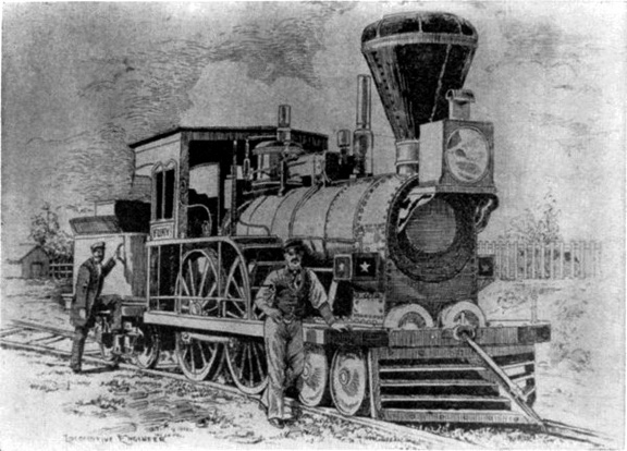 The Fury
The “Fury,” built for the Boston and Worcester Railroad in 1849 by Wilmarth. It was known as a “Shanghai” because of its great height. Diagram comparing the Pioneer (shaded drawing) with the Columbia, a standard 8-wheel engine of 1851....") Diagram comparing the Pioneer with the Columbia
Diagram comparing the Pioneer with the Columbia
Diagram comparing the Pioneer (shaded drawing) with the Columbia, a standard 8-wheel engine of 1851. (Drawing by J. H. White.) Columbia Hudson River Railroad Lowell Machine Shop, 1852 Wt. 271/2 tons (engine only) Cyl. 161/2 x 22 inches Wheel diam. 84 inches Pioneer Cumberland Valley Railroad Seth Wilmarth, 1851 121/2 tons 81/2 x 14 inches 54 inches “Pioneer” locomotive. (Drawing by J. H. White.)") Pioneer Locomotive
Pioneer Locomotive
“Pioneer” locomotive. (Drawing by J. H. White.) “Pioneer” locomotive,
(1) Safety valve,
(2) spring balance,
(3) steam jet
(4) dry pipe
(5...") Pioneer Locomotive
Pioneer Locomotive
“Pioneer” locomotive, (1) Safety valve, (2) spring balance, (3) steam jet (4) dry pipe (5) throttle lever (6) throttle (7) crown bar (8) front tube sheet (9) check valve (10) top rail (11) rear-boiler bracket (12) pedestal (13) rocker bearing (14) damper (15) grate (16) bottom rail (17) pump heater valve (18) cylinder lubricator (19) reversing lever (20) brake shoe (21) mud ring (22) blowoff cock (23) ashpan (Drawing by J. H. White.) “Pioneer” locomotive. (1) Air chamber, (2) reversing lever, (3) counterweight, (4) reversing sha...") Pioneer Locomotive
Pioneer Locomotive
“Pioneer” locomotive. (1) Air chamber, (2) reversing lever, (3) counterweight, (4) reversing shaft, (5) link hanger, (6) rocker, (7) feedwater line to boiler, (8) link block, (9) link, (10) eccentric, (11) pump plunger, (12) pump steamheater line, (13) feedwater pump, (14) wire netting [bonnet], (15) deflecting cone, (16) stack, (17) stack hopper. (Drawing by J. H. White.) Rear elevation of Pioneer and detail of valve shifter; valve face and valve. (Drawing by J. H. White...") Rear elevation of Pioneer
Rear elevation of Pioneer
Rear elevation of Pioneer and detail of valve shifter; valve face and valve. (Drawing by J. H. White.)
Patent Iron Suspension Railroad Bridge.
The undersigned would inform the officers of Railroads ...") Wendell Bollmans Patent Bridge
Wendell Bollmans Patent Bridge
Patent Iron Suspension Railroad Bridge. The undersigned would inform the officers of Railroads and others, that he is prepared to furnish Drawings and Estimates for Bridges, Roofs, etc., on the plan of Bollman’s Patent. The performance of these bridges, some of which have been in use for six years, has given entire satisfaction. Their simplicity of construction renders repairs easy and cheap, and by a peculiar connection of the Main and Panel Rods at the bottom of the Posts, all danger from the effects of expansion, which has heretofore been the chief objection to Iron Bridges, is entirely removed. J. H. TEGMEYER, Baltimore, Md. Shortly after the Harpers Ferry bridge reconstruction, Bollman was made foreman of bridges. It is ap...") Plan of Harpers Ferry Bridge
Plan of Harpers Ferry Bridge
Shortly after the Harpers Ferry bridge reconstruction, Bollman was made foreman of bridges. It is apparent that, on the basis of his practical ability, enhanced by the theoretical knowledge gained by intense self-study, he eventually came to assist Chief Engineer Benjamin H. Latrobe in bridge design. He later took this work over entirely as Latrobe’s attentions and talents were demanded in the location and extension of the line between Cumberland and Wheeling. Description of first trip in the car
When I got this car ready to run one night, I took it out a...") Duryea Automobile
Duryea Automobile
Description of first trip in the car When I got this car ready to run one night, I took it out and I had a young fellow with me; I thought I might need him to help push in case the car didn't work…. We ran from the area of the shop where it was built down on Taylor Street. We started out and ran up Worthington Street hill, on top of what you might call "the Bluff" in Springfield. Then we drove along over level roads from there to the home of Mr. Markham , and there we refilled this tank with water. [At this point he was asked if it was pretty well emptied by then.] Yes, I said in my account of it that when we got up there the water was boiling furiously. Well, no doubt it was. We refilled it and then we turned it back and drove down along the Central Street hill and along Maple, crossed into State Street, dropped down to Dwight, went west along Dwight to the vicinity where we had a shed that we could put the car in for the night. During that trip we had run, I think, just about six miles, maybe a little bit more. That was the first trip with this vehicle. It was the first trip of anything more than a few hundred yards that the car had ever made. It can be readily seen that this drawing was not made after the plan of the first vehicle.") A drawing and the first page of the specifications of the first patent issued to C. E. Duryea
A drawing and the first page of the specifications of the first patent issued to C. E. Duryea
It can be readily seen that this drawing was not made after the plan of the first vehicle. Drawing of 1885 Benz engine, showing
similarity in general appearance to Duryea engine. From
Karl ...") Drawing of 1885 Benz engine
Drawing of 1885 Benz engine
Drawing of 1885 Benz engine, showing similarity in general appearance to Duryea engine. From Karl Benz und sein Lebenswerk, Stuttgart, 1953. (Daimler-Benz Company publication.) Phantom illustration of Benz' first automobile.
(From Carl Benz, Father of the Automobile Industry,...") Phantom illustration of Benz' first automobile
Phantom illustration of Benz' first automobile
Phantom illustration of Benz' first automobile. (From Carl Benz, Father of the Automobile Industry, by L. M. Fanning, New York, 1955.) Illustration from U.S. patent 385087,
issued to Carl Benz, showing the horizontal plane
of the fly...") Illustration from U.S. patent 385087
Illustration from U.S. patent 385087
Illustration from U.S. patent 385087, issued to Carl Benz, showing the horizontal plane of the flywheel, a feature utilized by the Duryeas in their machine. Chauffeur driving two ladies") Chauffeur driving two ladies
Chauffeur driving two ladies
Chauffeur driving two ladies Chauffeur opening door for a lady") Chauffeur opening door for a lady
Chauffeur opening door for a lady
Chauffeur opening door for a lady") a ship in the reign of William the Conqueror
a ship in the reign of William the Conqueror") A ship of the reign of Henry VIII
A ship of the reign of Henry VIII") a ship of the reign of Edward IV
a ship of the reign of Edward IV") A Ship in the time of King Alfred
A Ship in the time of King Alfred") A ship in the time of Henry III
A ship in the time of Henry III