


") Renault Limousine
Renault Limousine Captain Charles Renard proved to be a worthy inheritor of the dreams, experience and inventions of t...") Renard’s dirigible, La France, 1884
Renard’s dirigible, La France, 1884
Captain Charles Renard proved to be a worthy inheritor of the dreams, experience and inventions of the first century of aëronautical votaries. He did not, indeed, have the picturesque madness displayed by some of his predecessors; he did not project schemes of marvelous originality or boldness; but he manifested uncommonly good judgment and excellent scientific method in combining the researches and contrivances of others with those of himself and his collaborator, Captain Krebs. As a consequence they produced the first man-carrying dirigible that ever returned against the wind to its starting point, and the first aërial vessel whose shape and dynamic adjustment even approximated the requirements of steady and swift navigation in a surrounding medium presenting various conditions of turbulence or calm.") Regas Four-Cylinder Car
Regas Four-Cylinder Car") Regas Air-cooled Motor
Regas Air-cooled Motor Rear elevation of Pioneer and detail of valve shifter; valve face and valve. (Drawing by J. H. White...") Rear elevation of Pioneer
Rear elevation of Pioneer
Rear elevation of Pioneer and detail of valve shifter; valve face and valve. (Drawing by J. H. White.)") Rambler Delivery
Rambler Delivery") Rambler Canopy-Top Touring Car
Rambler Canopy-Top Touring Car (911 visits)") Racing Deperdussin Monoplane (top view)
Racing Deperdussin Monoplane (top view) (804 visits) In the development of speed, some remarkable craft are built. Each year there is an international ai...") Racing Deperdussin Monoplane (side view)
Racing Deperdussin Monoplane (side view)
In the development of speed, some remarkable craft are built. Each year there is an international air race for the possession of the Gordon-Bennett trophy, and to win this designers build special craft. In tiny monoplanes, engines of high power are installed; and the sustaining wings are so reduced, to give a maximum speed, that the machines appear more like projectiles than flying craft. A purely racing-type monoplane is seen in figure.. It represents a Deperdussin, which, with an engine of 160 horse-power, reached a speed of 130 miles an hour. How small this machine was, in relation to its engine-power, will be realised from the fact that the sustaining surface of its wings amounted to only 104 square feet—far less lifting area, in fact, than Lilienthal used in his gliders. Wires and struts are reduced to a minimum; the body is tapered and smoothed. Such a machine, although it carries speed to an extreme, and is in reality a “freak,” teaches useful lessons. But though it provides data for the construction of high-speed scouts, a monoplane of this type would be useless for cross-country flying; and for the reason that it cannot be manœuvred, prior to an ascent, upon anything save the smoothest of ground. Its wings being so small, to ensure a maximum of speed, the machine will not rise until it has run forward a long distance across the ground; and during this run it attains a speed of nearly 90 miles an hour. At such a pace, unless the ground below its wheels was level, it would leap, swerve, and probably overturn. When alighting from a flight, also, again owing to the smallness of its wings, the craft has to plane down so fast that its pilot could not land safely unless he had below him a surface that was absolutely smooth. A. Propeller B. Shield to lessen wind resistance C. Sloping shield which encloses engine (also to minimise wind-pressure). Air passes between the shields B and C to cool the motor. D. Pilot’s seat E. Padded projection against which, when at high speed, the pilot rests his head F. Sustaining-plane Very slightly cambered G. Rudder H. Elevating-plane I. Landing wheels.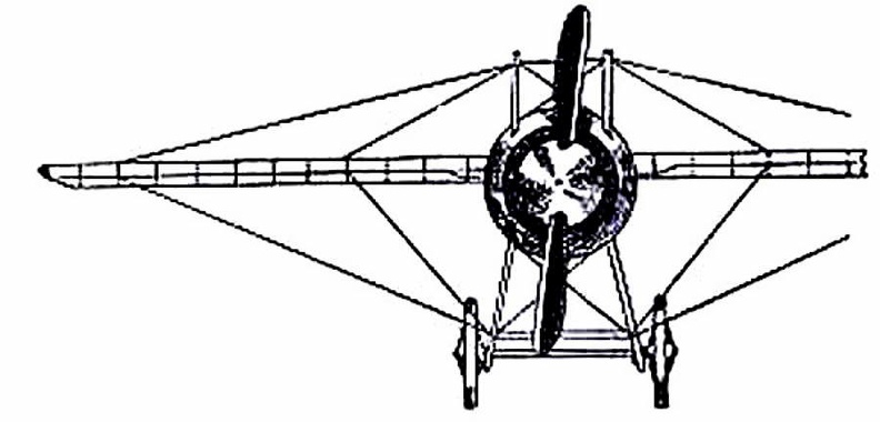
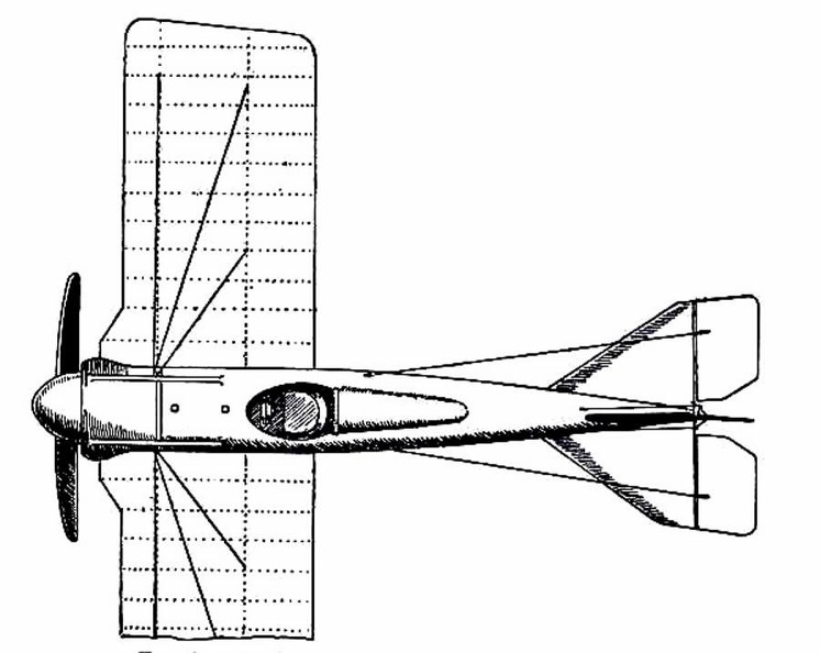
 (813 visits) showing the “stream-line” effect which is gained by tapering the body, also the simplification o...") Racing Deperdussin Monoplane (front view)
Racing Deperdussin Monoplane (front view)
showing the “stream-line” effect which is gained by tapering the body, also the simplification of the landing chassis, and the use of a minimum of wires. photo id=7984]") Racing
Racing R & L Stanhope. Rauch and Lang Carriage Co., Cleveland, Ohio
PRICE: $1,850
BODY: Stanhope
...") R & L Stanhope
R & L Stanhope
R & L Stanhope. Rauch and Lang Carriage Co., Cleveland, Ohio PRICE: $1,850 BODY: Stanhope SEATS: 2 persons WEIGHT: 1,600 pounds WHEEL-BASE: 73 inches TIRES, FRONT: 32 in., pneumatic TIRES, REAR: 32 in., pneumatic STEERING: Side lever BRAKES: On rear wheels and emergency SPRINGS: Semi-elliptic front; full elliptic rear FRAME: Steel HORSE-POWER: 1½ MOTOR: Hertner MOTOR SUSPENSION: Under body SPEED: 1–22 m. p. h. DISTANCE: 75 to 80 miles MOTOR-CONTROL: Lever at left of seat DRIVE: Double chain from countershaft") Queen Runabout
Queen Runabout Queen Elizabeth travelled in a coach, either the one built by Walter Rippon or that brought by Boone...") Queen Elizabeth’s Travelling Coach
Queen Elizabeth’s Travelling Coach
Queen Elizabeth travelled in a coach, either the one built by Walter Rippon or that brought by Boonen (who, by the way, was appointed her coachman), on some of her royal progresses through the kingdom. When she visited Warwick in 1572, at the request of the High Bailiff she “caused every part and side of the coach to be opened that all her subjects present might behold her, which most gladly they desired.” The vehicle which could thus be opened on “every part and side” is depicted incidentally in a work executed by Hoefnagel in 1582, which Markland believed to be probably the first engraved representation of an English coach. As will be seen from the reproduction here given, the body carried a roof or canopy on pillars, and the intervening spaces could be closed by means of curtains. Plane going down in flames") Plane going down in flames
Plane going down in flames
Plane going down in flames") Plan View of Pierce Four-cylinder Chassis
Plan View of Pierce Four-cylinder Chassis") Plan of typical New Haven sharpie showing design and construction characteristics
Plan of typical New Haven sharpie showing design and construction characteristics") Plan of the chassis of the FIAT Car
Plan of the chassis of the FIAT Car") Plan of North Carolina sharpie schooner taken from remains of boat
Plan of North Carolina sharpie schooner taken from remains of boat Plan of North Carolina sharpie of the 1880's") Plan of North Carolina sharpie of the 1880's
Plan of North Carolina sharpie of the 1880's
Plan of North Carolina sharpie of the 1880's Shortly after the Harpers Ferry bridge reconstruction, Bollman was made foreman of bridges. It is ap...") Plan of Harpers Ferry Bridge
Plan of Harpers Ferry Bridge
Shortly after the Harpers Ferry bridge reconstruction, Bollman was made foreman of bridges. It is apparent that, on the basis of his practical ability, enhanced by the theoretical knowledge gained by intense self-study, he eventually came to assist Chief Engineer Benjamin H. Latrobe in bridge design. He later took this work over entirely as Latrobe’s attentions and talents were demanded in the location and extension of the line between Cumberland and Wheeling.") Plan of a large Chesapeake Bay sharpie taken from remains of boat
Plan of a large Chesapeake Bay sharpie taken from remains of boat") Plan of a Chesapeake Bay terrapin smack
Plan of a Chesapeake Bay terrapin smack But a means of adapting a mono-rail to every condition had some time before been thought out. In 188...") Plan of a Behr Mono-Railway Car
Plan of a Behr Mono-Railway Car
But a means of adapting a mono-rail to every condition had some time before been thought out. In 1883-4 Charles Lartigue, the eminent French engineer, developing the principle conceived by the great Telford, constructed some small lines in Tunis and Algeria for carrying esparto grass. The cars were drawn by animals in a special form of mono-rail, the model upon which Mr. F. B. Behr, ASS. INST. C.E.—who modestly disclaims all originality in the matter—has worked for years, greatly improving in practical details the original design, and constructing for the first time mono-rail trains that have been successful in the carriage of both goods and passengers by steam and electricity. “Pioneer” locomotive. (1) Air chamber, (2) reversing lever, (3) counterweight, (4) reversing sha...") Pioneer Locomotive
Pioneer Locomotive
“Pioneer” locomotive. (1) Air chamber, (2) reversing lever, (3) counterweight, (4) reversing shaft, (5) link hanger, (6) rocker, (7) feedwater line to boiler, (8) link block, (9) link, (10) eccentric, (11) pump plunger, (12) pump steamheater line, (13) feedwater pump, (14) wire netting [bonnet], (15) deflecting cone, (16) stack, (17) stack hopper. (Drawing by J. H. White.) “Pioneer” locomotive. (Drawing by J. H. White.)") Pioneer Locomotive
Pioneer Locomotive
“Pioneer” locomotive. (Drawing by J. H. White.) “Pioneer” locomotive,
(1) Safety valve,
(2) spring balance,
(3) steam jet
(4) dry pipe
(5...") Pioneer Locomotive
Pioneer Locomotive
“Pioneer” locomotive, (1) Safety valve, (2) spring balance, (3) steam jet (4) dry pipe (5) throttle lever (6) throttle (7) crown bar (8) front tube sheet (9) check valve (10) top rail (11) rear-boiler bracket (12) pedestal (13) rocker bearing (14) damper (15) grate (16) bottom rail (17) pump heater valve (18) cylinder lubricator (19) reversing lever (20) brake shoe (21) mud ring (22) blowoff cock (23) ashpan (Drawing by J. H. White.) Pilot and passenger") Pilot and passenger
Pilot and passenger
Pilot and passenger") Pierce Two-Cylinder Arrow
Pierce Two-Cylinder Arrow") Pierce Stanhope
Pierce Stanhope As will be seen from the accompanying engraving, \"Pickering's American Velocipede,\" manufactured by ...") Pickering's American Velocipede
Pickering's American Velocipede
As will be seen from the accompanying engraving, "Pickering's American Velocipede," manufactured by Messrs. Pickering & Davis, differs very materially from the French model, so generally used by other manufacturers. It is claimed that it is more simple and durable, lighter and stronger. The reach or frame of this velocipede is made of hydraulic tubing. The gun-metal bearings are so attached that, when worn, they may be replaced by others, which are interchangeable like the parts of sewing-machines and fire-arms. The axle is so constructed as to constitute, in itself, an oil box. It is made tubular, and closed at either end with a screw, on the removal of which it is filled with lard oil. Cotton lamp-wick is placed loosely in the tubular axle and the oil is by this means fed to the bearing, as fast as required, through the small holes made for the purpose in the centre of the axle. The saddle is supported on a spiral spring, giving an elastic seat; it is brought well back, so that the rider maintains an erect position, and is adjustable to suit the length of limb of the rider. The tiller or steering handle is constructed with a spring so that the hands are relieved from the jolting that they would otherwise receive while running over rough ground. The stirrups or crank pedals, are three-sided, with circular flanges at each end, fitted to turn on the crank pins, so that the pressure of the foot will always bring one of the three sides into proper position. They are so shaped as to allow of the use of the forepart of the foot, bringing the ankle joint into play, relieving the knee, and rendering propulsion easier than when the shank of the foot alone is used. The connecting apparatus differs from that of the French vehicle in that the saddle bar serves only as a seat and brake, and is not attached to the rear wheel. By a simple pressure forward against the tiller, and a backward pressure against the tail of the saddle, the saddle spring is compressed, and the brake attached to it brought firmly down against the wheel. Messrs. Pickering & Davis have a large manufactory, and are the constant recipients of orders from all parts of the country. Mr. Pickering has always been a practical machinist, and personally superintends the structure of each machine turned out. Phillips built the strange-looking machine. It resembled, more than anything else, a huge Venetian b...") Phillips’s Experimental Craft
Phillips’s Experimental Craft
Phillips built the strange-looking machine. It resembled, more than anything else, a huge Venetian blind; and he adopted this form so as to introduce as many narrow planes as possible. There were, as a matter of fact, fifty in the machine, each 22 feet long and only 1½ inch wide. The craft, as can be seen, was mounted on a light carriage which, having wheels fitted to it, ran round and round upon a railed track. A steam engine was used as motive power, driving a two-bladed propeller at the rate of 400 revolutions a minute. The machine was so arranged on its metals that, although the rear wheels could raise themselves and show whether the planes exercised a lift, the front one was fixed to its track—thus preventing the apparatus from leaping into the air, overturning, and perhaps wrecking itself. Tests with the machine were successful. The lifting influence of the planes, when the engine drove them forward, was sufficient to raise the rear wheels from the track; and they did so even when a weight of 72 lbs., in addition to that of the apparatus, had been placed upon the carriage. In his main object, then, Phillips succeeded; and that was to show the lifting power of his planes. But his apparatus had not the makings of a practical aeroplane. He gained for himself, nevertheless, a name that has lived and will live. Phantom illustration of Benz' first automobile.
(From Carl Benz, Father of the Automobile Industry,...") Phantom illustration of Benz' first automobile
Phantom illustration of Benz' first automobile
Phantom illustration of Benz' first automobile. (From Carl Benz, Father of the Automobile Industry, by L. M. Fanning, New York, 1955.) PRICE: $2,800
BODY: Mercedes
SEATS: 5 persons
WEIGHT: 2,550 pounds
WHEEL-BASE: 111 inches
TREAD...") Pennsylvania, 35 H.P. Pennsylvania Auto Motor Co., Phil., Pa.
Pennsylvania, 35 H.P. Pennsylvania Auto Motor Co., Phil., Pa.
PRICE: $2,800 BODY: Mercedes SEATS: 5 persons WEIGHT: 2,550 pounds WHEEL-BASE: 111 inches TREAD: 56 inches TIRES, FRONT: 34 × 4 in. TIRES, REAR: 34 × 4 in. STEERING: Worm and nut BRAKES: Double on rear wheels SPRINGS: Front, 40 in. long; Rear, platform type FRAME: Pressed steel BORE: 4½ in.; STROKE: 5 in. CYLINDERS: 4 vertical, cast separate VALVE ARRANGEMENT: Same side MOTOR SUSPENSION: Direct from sub-frame COOLING: Water; cellular radiator IGNITION: Jump spark CURRENT SUPPLY: Storage battery CARBURETER: Schebler LUBRICATION: Force feed MOTOR-CONTROL: Spark and throttle CLUTCH: Cone CHANGE GEAR: Sliding type SPEEDS: 3 forward and reverse CHANGE-GEAR CONTROL: Selective system DRIVE: Shaft In 1871 M. A. Penaud produced the interesting toy aëroplane shown in the figure. The model is prope...") Penaud’s aëroplane toy, 1871
Penaud’s aëroplane toy, 1871
In 1871 M. A. Penaud produced the interesting toy aëroplane shown in the figure. The model is propelled horizontally forward by a single screw, actuated by twisted rubber, and is fastened, as shown, to the middle of a long stick or backbone. The center of mass of the machine is well to the front, tending to plunge the model earthward like a heavy-headed arrow; but this down-diving is promptly checked by the tiny rudder which is so inclined as to counteract the diving proclivity. That is to say the rudder dips so as to receive the aërial impact on its upper surface; which impact increases with the speed of flight and causes the bow to rise, until the weight before the wings just balances the impact on the rudder at the rear. The equilibrium is thus automatic, on the principle expounded by Sir George Cayley sixty years earlier. (872 visits)") Parts of a motorbike (2)
Parts of a motorbike (2)") Parts of a motorbike
Parts of a motorbike When you stop in a street, don't forget to reach out first, as a sign for the vehicle following you....") Parking
Parking
When you stop in a street, don't forget to reach out first, as a sign for the vehicle following you. Place your car neatly along the sidewalk, not crooked or in such a way that traffic is obstructed by it. You must intervene two vehicles or cars get into the car, then drive a little further, and then reverse between the cars. Do not drive straight over to the left side of the street, against the traffic, but drive to the right and then turn along the direction of the traffic, until you are in front of the house, where you want to be. [Translated online from the Dutch ]") Packard Model L
Packard Model L") P.G. and E. Car 37, A wooden type, on the 3 line, 1941
P.G. and E. Car 37, A wooden type, on the 3 line, 1941") P.G. and E Carbarns at 28t hand N, 1914
P.G. and E Carbarns at 28t hand N, 1914") P.G. and E Car at Oak Park
P.G. and E Car at Oak Park When overtaking a tram, also pay attention to the possibility that someone will jump in front of or ...") Overtaking a tram
Overtaking a tram
When overtaking a tram, also pay attention to the possibility that someone will jump in front of or from the tram. Giving a good signal and leaving as much road width as possible between the tram and your car is required. To catch up with a steam tram that hurls its plume over the road, and you it obstructs the view, it is advisable to wait until the wind chases away the steam. For the distance required to overtake a fast-moving vehicle such as a tram is too long, that the chance would not become too great that, in time, it would take to catch up with the plume of steam and drive through it. , in the meantime, a road obstruction would arise from the other side, which you would not have been able to see approaching. If you come across such a vehicle, moderate your speed so that you can stop vehicles suddenly emerging from that plume of steam. Give a strong signaland if necessary, stop the car on the right side of the road, until the tram has passed. Because then you have the most certainty, because then only a vehicle moving faster or as fast as the tram can cause danger. And this danger can be averted by giving a signal and keeping the right side of the road well. [Translated online from the Dutch ]") Out for a ride
Out for a ride Original Wright Biplane") Original Wright Biplane
Original Wright Biplane
Original Wright Biplane") Orient Buckboard
Orient Buckboard") One of the Panhards
One of the Panhards To sell the great quantities of fish they dragged up from the Banks or nearer home, foreign markets ...") On The Banks
On The Banks
To sell the great quantities of fish they dragged up from the Banks or nearer home, foreign markets must needs be found. England and the European countries took but little of this sort of provender, and moreover England, France, Holland, and Portugal had their own fishing fleets on the Banks.") Olds Touring Runabout
Olds Touring Runabout") Olds Tonneau Car
Olds Tonneau Car") old times sketch
old times sketch Octave Chanute, born in France and reared in America, was one of the first men to make a scientific ...") Octave Chanute experimenting with his gliders on the Michigan sand dunes
Octave Chanute experimenting with his gliders on the Michigan sand dunes
Octave Chanute, born in France and reared in America, was one of the first men to make a scientific approach to the problem of flying machines. A thorough scientist, he had followed the progress of all flight experiments the world over. He built gliders with one, two, and even five pairs of wings and tested all of them on the sand dunes of Lake Michigan. His most successful glides were made with a biplane glider. In 1894, he published a book called Progress of Flying Machines, which covered all the efforts of men like himself who had experimented with man-carrying gliders and flying machines. Northrop A-17
Front Side
...") Northrop A-17
Northrop A-17
Northrop A-17 Front Side Perspective Bottom Top North American P-51
Front ...") North American P-51
North American P-51
North American P-51 Front Side Perspective Bottom Top North American O-47A & B
Front &...") North American O-47A& B
North American O-47A& B
North American O-47A & B Front Side Perspective Bottom Top North American B-25 C & D
Front ...") North American B-25 C & D
North American B-25 C & D
North American B-25 C & D Front Side Perspective Bottom Top North American AT-6A
Front  ...") North American AT-6A
North American AT-6A
North American AT-6A Front Side Perspective Bottom Top Naval battle with planes launched from ships") Naval battle with planes launched from ships
Naval battle with planes launched from ships
Naval battle with planes launched from ships") National Gasoline Car
National Gasoline Car The fitting of several motors has been shown to be practical; and it has the obvious advantage that,...") Multiple-engined craft
Multiple-engined craft
The fitting of several motors has been shown to be practical; and it has the obvious advantage that, should one fail while in the air, the other or others will maintain a craft in flight. In such a machine as would fly the Atlantic, for example, it is proposed to fit four motors developing 800 h.p., and to carry a couple of mechanics who would constantly be tending them. Thus, should one engine develop trouble, its repair could be effected without descent, and with no worse result than a temporary fall in speed. In the figure is shown a method by which three Gnome motors may be fitted to a biplane. A. First engine (a 50-h.p. Gnome) B. Second engine (which is on the same shaft, but will run independently) C. Third Gnome engine, also an independent unit D. Four-bladed propeller (mounted higher than the crank-shaft bearing the engines, and driven by a chain gearing).