


 (649 visites) Their first glider was a biplane, with 165 square feet of lifting surface, as illustrated in figure;...") The 1900 Wright Glider (operator’s position)
The 1900 Wright Glider (operator’s position)
Their first glider was a biplane, with 165 square feet of lifting surface, as illustrated in figure; several of its features need explanation. First there is the position of the operator; he can be seen lying prone across the centre of the lower plane. This attitude was adopted by the Wrights to minimise wind-pressure. Should a man be upright in his machine, they calculated that his body would, as the glider passed through the air, offer an appreciable resistance; while, in lying flat, he would offer scarcely any resistance at all. Apart from governing the ascending or descending movement, there was the question of preventing a ma...") The Wright Wing-warp
The Wright Wing-warp
Apart from governing the ascending or descending movement, there was the question of preventing a machine from slipping sideways; and this the Wrights solved ingeniously. They saw, of course, that when their glider lurched to one side or the other, they would need some power to tilt it back again. So they devised a system by which the plane-ends of their machine—being made flexible—might be warped, or caused to shift up and down. This action the operator controlled, as he lay across the lower plane, by a movement of cords, and its operation is shown in Figure. The effect upon the machine may be described thus: should a wind-gust tilt down one plane-end, the “warp” upon that side of the machine was drawn down also, and the effect of this—seeing that it caused the plane to assume a steeper angle to the air and exercise a greater lift—was to raise the plane-ends that had been driven down by the gust. By a system of connecting the control cords, this balancing influence was made to act with double force; when one wing warped down, the other moved up; and, in this way, while the side of the machine tilted down was made to rise, the other plane-ends, which had been lifted, were made to descend. A dual righting influence was thus obtained. This system, which imitates the flexing movements made by a bird, was an important device; the Wrights patented it—combining the movement with an action of the rudder—and brought cases at law to enforce their rights. Two assistants took the machine by its plane-ends and ran forward with it, the pilot assuming before...") Launching the Wright Glider
Launching the Wright Glider
Two assistants took the machine by its plane-ends and ran forward with it, the pilot assuming beforehand his position upon the plane; then, when they had gained a pace sufficient for the machine to soar, they released their hold and it glided forward. Beneath the glider, under the centre of the lower plane, there were two wooden skates or runners, and these took the weight of the machine when it alighted, and allowed it to slide forward across the ground before coming to rest. By the use of these landing skids, and by steering at as fine an angle as possible, the Wrights found they could touch ground, even at 20 miles an hour and lying across the machine, without injury either to themselves or the craft. How lightly a petrol engine can be made was demonstrated by the firm constructing the Antoinette mo...") Man lifting a 100 horse-power aeroplane motor
Man lifting a 100 horse-power aeroplane motor
How lightly a petrol engine can be made was demonstrated by the firm constructing the Antoinette motor, with which many of the pioneers fitted their craft. A 16-cylinder engine was made so that a man could raise it upon his shoulders—as shown in Figure —and carry it without much difficulty; and yet this same motor, which one man could lift from the ground, developed 100 horse-power. When the Wrights had built an engine, there was still the question how they should make it drive the...") Wright Motor and Propellers
Wright Motor and Propellers
When the Wrights had built an engine, there was still the question how they should make it drive their aeroplane. They inclined naturally to the idea of an aerial propeller. Two courses lay open to them; they could fit one propeller running at high speed and coupled directly to the motor, or they could use two propellers, revolving at slower speed and geared in some way to the engine. They decided upon the latter course, placing two propellers behind the main planes of their machine and driving them from the engine by means of light chains, these running in guiding tubes. This system of propulsion is shown. A. Motor; B. Gear-wheels upon motor crank-shaft; C.C. Tubes carrying driving chains; D.D. Sprocket-wheels over which chains pass; E.E. Propellers. A.A.—Main-planes; B. Double front elevator; C. Rudder (two narrow vertical planes); D. Motor; E. P...") The Wright Biplane
The Wright Biplane
A.A.—Main-planes; B. Double front elevator; C. Rudder (two narrow vertical planes); D. Motor; E. Propellers; F. Pilot’s lever; G. Skids upon which machine landed. It is now possible to describe, as a completed craft, the Wright power-driven plane; The picture shows its appearance; and in looking at it one is struck by the fact that, save for one or two modifications, and the fitting of motor and propellers, the machine is practically a glider, such as the Wrights used for soaring tests. Of the changes to be observed, the most interesting concern the elevator and rear-rudder. The former, it will be seen, has a double plane; it is, in fact, a smaller biplane on the principle of the main-planes. Needing to increase the surface of the elevator, the brothers fixed one plane above another so as to make the construction stronger and occupy less space. The rear-rudder, acting like that of a ship. In the picture the operator is seen in the driving seat; and near him will be observed the motor whi...") Driving seat of Wright Biplane
Driving seat of Wright Biplane
In the picture the operator is seen in the driving seat; and near him will be observed the motor which drives the craft. In his left hand—that is to say in the one nearest us—he grasps the lever which operates the elevating planes. The rod from lever to plane can be seen, and the motions the pilot makes are these: should he wish to rise, he draws the lever towards him and tilts up the elevating planes in the manner already described, increasing the lifting power of the main-planes and so causing the machine to ascend; by a reverse movement of the lever—by pushing it away from him, that is to say—he makes the craft glide downward. A. Biplane; B. Rail; C. Rope passing from the aeroplane round the pulley-wheel (D.) and thence to th...") Wright Launching Rail
Wright Launching Rail
A. Biplane; B. Rail; C. Rope passing from the aeroplane round the pulley-wheel (D.) and thence to the derrick (E.); (F.) Falling weight. Details of propulsion and control being arranged, there remained the question of how the machine should be launched into the air. In their gliding tests, it will be remembered, the Wrights employed assistants, who held the machine by the wing-tips and ran forward with it. But the weight of the power-driven machine, and its greater size, prevented such a plan as this. They decided, therefore, to launch it from a rail, and to aid its forward speed, at the moment of taking the air, by a derrick and a falling weight. In the launching of gliders, some French experimenters showed ingenuity. The brothers Voisin, for in...") Voisin Glider towed by a motor-car
Voisin Glider towed by a motor-car
In the launching of gliders, some French experimenters showed ingenuity. The brothers Voisin, for instance, who played a prominent part in the early tests in France, adopted the plan illustrated. The gilder was towed by a motor-car across an open stretch of ground; then, when its speed was sufficient for the planes to lift, it rose and flew behind the car like a kite. A form of glider, mounted upon hollow wooden floats—anticipating the sea-plane of to-day—and tow...") Voisin Glider on the river Seine
Voisin Glider on the river Seine
A form of glider, mounted upon hollow wooden floats—anticipating the sea-plane of to-day—and towed upon the river Seine by a motor-boat. This gilder also, when its speed became sufficient, rose into the air. In the construction of the machine, a biplane, one notes resemblances to the method of the Wrights; and yet generally the craft is dissimilar. It was not until 1906, at a time when the Wright aeroplane was capable of long flights, that a real ...") Santos-Dumont’s Biplane which flew at Bagetelle
Santos-Dumont’s Biplane which flew at Bagetelle
It was not until 1906, at a time when the Wright aeroplane was capable of long flights, that a real French success was obtained; and then the flights made were brief, and carried out with a craft that was admittedly crude. It was a biplane of curious construction, built by the Voisin brothers for M. Santos-Dumont—a rich Brazilian who had spent money freely upon airships, and had been occupied, for some time before the Voisins made him this machine, with a craft having propellers to lift it vertically from the ground. Abandoning this idea, he devoted himself to the machine the Voisins built, which is seen in the picture. The 16 h.p. Uni-motorcycle, with spring suspension, magneto ignition, free engine and wheel steering...") A Possibility of Motorcycling in the Future
A Possibility of Motorcycling in the Future
The 16 h.p. Uni-motorcycle, with spring suspension, magneto ignition, free engine and wheel steering. The 8 h.p. twin cylinder Uni, with wheel steering and free engine. The power plant slides upon rails...") A Possibility of Motorcycling in the Future
A Possibility of Motorcycling in the Future
The 8 h.p. twin cylinder Uni, with wheel steering and free engine. The power plant slides upon rails at the rear platform by means of a cable actuated from the lever beside the driver") A ship in the time of Henry III
A ship in the time of Henry III") A Ship in the time of King Alfred
A Ship in the time of King Alfred") a ship of the reign of Edward IV
a ship of the reign of Edward IV") A ship of the reign of Henry VIII
A ship of the reign of Henry VIII") a ship in the reign of William the Conqueror
a ship in the reign of William the Conqueror Chauffeur opening door for a lady") Chauffeur opening door for a lady
Chauffeur opening door for a lady
Chauffeur opening door for a lady Chauffeur driving two ladies") Chauffeur driving two ladies
Chauffeur driving two ladies
Chauffeur driving two ladies Illustration from U.S. patent 385087,
issued to Carl Benz, showing the horizontal plane
of the fly...") Illustration from U.S. patent 385087
Illustration from U.S. patent 385087
Illustration from U.S. patent 385087, issued to Carl Benz, showing the horizontal plane of the flywheel, a feature utilized by the Duryeas in their machine. Phantom illustration of Benz' first automobile.
(From Carl Benz, Father of the Automobile Industry,...") Phantom illustration of Benz' first automobile
Phantom illustration of Benz' first automobile
Phantom illustration of Benz' first automobile. (From Carl Benz, Father of the Automobile Industry, by L. M. Fanning, New York, 1955.) Drawing of 1885 Benz engine, showing
similarity in general appearance to Duryea engine. From
Karl ...") Drawing of 1885 Benz engine
Drawing of 1885 Benz engine
Drawing of 1885 Benz engine, showing similarity in general appearance to Duryea engine. From Karl Benz und sein Lebenswerk, Stuttgart, 1953. (Daimler-Benz Company publication.) It can be readily seen that this drawing was not made after the plan of the first vehicle.") A drawing and the first page of the specifications of the first patent issued to C. E. Duryea
A drawing and the first page of the specifications of the first patent issued to C. E. Duryea
It can be readily seen that this drawing was not made after the plan of the first vehicle. Description of first trip in the car
When I got this car ready to run one night, I took it out a...") Duryea Automobile
Duryea Automobile
Description of first trip in the car When I got this car ready to run one night, I took it out and I had a young fellow with me; I thought I might need him to help push in case the car didn't work…. We ran from the area of the shop where it was built down on Taylor Street. We started out and ran up Worthington Street hill, on top of what you might call "the Bluff" in Springfield. Then we drove along over level roads from there to the home of Mr. Markham , and there we refilled this tank with water. [At this point he was asked if it was pretty well emptied by then.] Yes, I said in my account of it that when we got up there the water was boiling furiously. Well, no doubt it was. We refilled it and then we turned it back and drove down along the Central Street hill and along Maple, crossed into State Street, dropped down to Dwight, went west along Dwight to the vicinity where we had a shed that we could put the car in for the night. During that trip we had run, I think, just about six miles, maybe a little bit more. That was the first trip with this vehicle. It was the first trip of anything more than a few hundred yards that the car had ever made. Shortly after the Harpers Ferry bridge reconstruction, Bollman was made foreman of bridges. It is ap...") Plan of Harpers Ferry Bridge
Plan of Harpers Ferry Bridge
Shortly after the Harpers Ferry bridge reconstruction, Bollman was made foreman of bridges. It is apparent that, on the basis of his practical ability, enhanced by the theoretical knowledge gained by intense self-study, he eventually came to assist Chief Engineer Benjamin H. Latrobe in bridge design. He later took this work over entirely as Latrobe’s attentions and talents were demanded in the location and extension of the line between Cumberland and Wheeling.
Patent Iron Suspension Railroad Bridge.
The undersigned would inform the officers of Railroads ...") Wendell Bollmans Patent Bridge
Wendell Bollmans Patent Bridge
Patent Iron Suspension Railroad Bridge. The undersigned would inform the officers of Railroads and others, that he is prepared to furnish Drawings and Estimates for Bridges, Roofs, etc., on the plan of Bollman’s Patent. The performance of these bridges, some of which have been in use for six years, has given entire satisfaction. Their simplicity of construction renders repairs easy and cheap, and by a peculiar connection of the Main and Panel Rods at the bottom of the Posts, all danger from the effects of expansion, which has heretofore been the chief objection to Iron Bridges, is entirely removed. J. H. TEGMEYER, Baltimore, Md. “Pioneer” locomotive,
(1) Safety valve,
(2) spring balance,
(3) steam jet
(4) dry pipe
(5...") Pioneer Locomotive
Pioneer Locomotive
“Pioneer” locomotive, (1) Safety valve, (2) spring balance, (3) steam jet (4) dry pipe (5) throttle lever (6) throttle (7) crown bar (8) front tube sheet (9) check valve (10) top rail (11) rear-boiler bracket (12) pedestal (13) rocker bearing (14) damper (15) grate (16) bottom rail (17) pump heater valve (18) cylinder lubricator (19) reversing lever (20) brake shoe (21) mud ring (22) blowoff cock (23) ashpan (Drawing by J. H. White.) “Pioneer” locomotive. (Drawing by J. H. White.)") Pioneer Locomotive
Pioneer Locomotive
“Pioneer” locomotive. (Drawing by J. H. White.)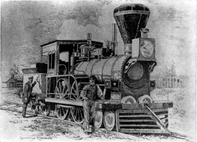 The Fury
The “Fury,” built for the Boston and Worcester Railroad in 1849 by Wilmarth. It was known as a “Shanghai” because of its great height. Diagram comparing the Pioneer (shaded drawing) with the Columbia, a standard 8-wheel engine of 1851....") Diagram comparing the Pioneer with the Columbia
Diagram comparing the Pioneer with the Columbia
Diagram comparing the Pioneer (shaded drawing) with the Columbia, a standard 8-wheel engine of 1851. (Drawing by J. H. White.) Columbia Hudson River Railroad Lowell Machine Shop, 1852 Wt. 271/2 tons (engine only) Cyl. 161/2 x 22 inches Wheel diam. 84 inches Pioneer Cumberland Valley Railroad Seth Wilmarth, 1851 121/2 tons 81/2 x 14 inches 54 inches Rear elevation of Pioneer and detail of valve shifter; valve face and valve. (Drawing by J. H. White...") Rear elevation of Pioneer
Rear elevation of Pioneer
Rear elevation of Pioneer and detail of valve shifter; valve face and valve. (Drawing by J. H. White.) “Pioneer” locomotive. (1) Air chamber, (2) reversing lever, (3) counterweight, (4) reversing sha...") Pioneer Locomotive
Pioneer Locomotive
“Pioneer” locomotive. (1) Air chamber, (2) reversing lever, (3) counterweight, (4) reversing shaft, (5) link hanger, (6) rocker, (7) feedwater line to boiler, (8) link block, (9) link, (10) eccentric, (11) pump plunger, (12) pump steamheater line, (13) feedwater pump, (14) wire netting [bonnet], (15) deflecting cone, (16) stack, (17) stack hopper. (Drawing by J. H. White.) An aeroplpane in war") An aeroplpane in war
An aeroplpane in war
An aeroplpane in war Aviators taking photographs") Aviators taking photographs
Aviators taking photographs
Aviators taking photographs Battle between aeroplane and British tank") Battle between aeroplane and British tank
Battle between aeroplane and British tank
Battle between aeroplane and British tank Battleplanes convoying photographing aeroplanes") Battleplanes convoying photographing aeroplanes
Battleplanes convoying photographing aeroplanes
Battleplanes convoying photographing aeroplanes Blimp bombing a submarine") Blimp bombing a submarine
Blimp bombing a submarine
Blimp bombing a submarine Dropping off in parachute from flaming balloon") Dropping off in parachute from flaming balloon
Dropping off in parachute from flaming balloon
Dropping off in parachute from flaming balloon Fast mail-carrying aeroplanes will make postal deliveries everywhere") Fast mail-carrying aeroplanes will make postal deliveries everywhere
Fast mail-carrying aeroplanes will make postal deliveries everywhere
Fast mail-carrying aeroplanes will make postal deliveries everywhere Fighting Zeppelin raiders") Fighting Zeppelin raiders
Fighting Zeppelin raiders
Fighting Zeppelin raiders") Group of French Aviators
Group of French Aviators Naval battle with planes launched from ships") Naval battle with planes launched from ships
Naval battle with planes launched from ships
Naval battle with planes launched from ships Original Wright Biplane") Original Wright Biplane
Original Wright Biplane
Original Wright Biplane Pilot and passenger") Pilot and passenger
Pilot and passenger
Pilot and passenger Plane going down in flames") Plane going down in flames
Plane going down in flames
Plane going down in flames (1401 visites) Scouting over the ruined region between the lines (no man’s land)") Scouting over the ruined region between the lines (no man’s land)
Scouting over the ruined region between the lines (no man’s land)
Scouting over the ruined region between the lines (no man’s land) Ship saved by life line thrown from a rescue airship
[Not sure what it did to save the boat]") Ship saved by life line thrown from a rescue airship
Ship saved by life line thrown from a rescue airship
Ship saved by life line thrown from a rescue airship [Not sure what it did to save the boat] Some types of American and foreign aeroplanes") Some types of American and foreign aeroplanes
Some types of American and foreign aeroplanes
Some types of American and foreign aeroplanes Some types of American and foreign aeroplanes") Some types of American and foreign aeroplanes
Some types of American and foreign aeroplanes
Some types of American and foreign aeroplanes It was on June 5, 1783 that Stephen and Joseph Montgolfier, two French brothers, sent up the first b...") The ascension of Montgolfier’s balloon
The ascension of Montgolfier’s balloon
It was on June 5, 1783 that Stephen and Joseph Montgolfier, two French brothers, sent up the first balloon. You can just imagine the amazement it caused when it arose from the ground. The depth bomb destroys a U-Boat") The depth bomb destroys a U-Boat
The depth bomb destroys a U-Boat
The depth bomb destroys a U-Boat The seaplane shoots off the catapult") The seaplane shoots off the catapult
The seaplane shoots off the catapult
The seaplane shoots off the catapult British plane flying over the trenches in the great war") They swoop down over the trenches
They swoop down over the trenches
British plane flying over the trenches in the great war Air raid siren in Paris") Tooting the sirens of warning
Tooting the sirens of warning
Air raid siren in Paris German plane crashed into an American warship") A mass of wreckage that strikes the deck of one of our warships
A mass of wreckage that strikes the deck of one of our warships
German plane crashed into an American warship An aeroplane is a necessity in times of peace") An aeroplane is a necessity in times of peace
An aeroplane is a necessity in times of peace
An aeroplane is a necessity in times of peace Launched in 1863
Among the numerous huge monsters constituting the iron-clad fleet of England, ...") The 'Minotaur'
The 'Minotaur'
Launched in 1863 Among the numerous huge monsters constituting the iron-clad fleet of England, the Minotaur, is one of the most gigantic and formidable; and the sister ships, the Agincourt and Northumberland, all of precisely the same tonnage, power, rig, and equipment, are the largest and most powerful ships in the navy. The Minotaur was built at Blackwall, by the Thames Ship Building company and the engines were constructed by Messrs. Penn, of Deptford. She is 6,621 ton's measurement, and propelled by screw engins of 1,350 horsepower, with a speed of 15 knots an hour. She is 400 feet in length by 59 in width, and carries in all thirty-four of the heaviest guns used afloat. Among these which form her chief batter on the main deck are four 300-pounder Armstrongs. I will now give you a sectional division of a first-rate line-of-battle ship. Such a ship, carrying ...") Section of First-rate Man-of-War
Section of First-rate Man-of-War
I will now give you a sectional division of a first-rate line-of-battle ship. Such a ship, carrying 120 or more guns, has four decks on which her guns are placed. The highest is open to the air, and is called the UPPER DECK At the after part, extending a little way beyond the mizen-mast, there is a raised platform, called the POOP. It has no guns on it. On the main deck is the steering-wheel, with the binnacle in front of it. The after part of this deck between the poop and the main-mast is called the quarter-deck, and is the place where the officers especially walk. The part under the poop is divided into cabins, appropriated to the use of the captain. Here, also, is a clerk's office and a pantry. Between the main and fore-mast the large boats are stowed, and on either side are the gangways at which sentries are stationed. The next deck under this is called the MAIN DECK. In the after part is the admiral's cabin. Immediately under the boats is a pen for the officers' live-stock ; and just abaft the fore-mast is the galley, or kitchen. The third deck from the upper is called the MIDDLE DECK. The after part is fitted up for the lieutenants, chaplain, surgeon, paymaster, marine officers, &c., and called the WARD-ROOM. In the fore part of the deck is placed the sick-bay, a compartment fitted up as a hospital ; about the centre of this deck is one of the capstans. The fourth from the upper is called the LOWER or GUN DECK. In the after part is the GUN-ROOM, where the midshipmen, and other junior officers, mess. The tiller of the rudder works through the gun-room just above their heads. A second capstan is placed on this deck ; and forward are the riding-bitts for securing the cables. It is the lowest deck on which guns are carried. The ORLOP DECK is the fifth deck from the upper. It has no guns or ports, though lighted up by bull's eyes or scuttles. In the after part is the purser's issue-room ; next to it is the after cockpit, where the midshipmen and other junior officers sleep in hammocks. Before it again will be found the sail-room, where the sails are kept, and the cable-tiers, where the cables are stowed. Before it again, just abaft the fore-mast, is the fore cockpit, and the warrant officers' cabins, while right in the head of the ship are the carpenter's and boatswain's stores. Low as we have got, we have still further to go down to the HOLD, which, if it may be so called, is the sixth deck from the highest. It is often divided into two decks for the greater convenience of stowage. Here are the FORE AND AFTER MAGAZINES, WATER TANKS, WINE AND SPIRIT ROOM, CHAIN CABLE LOCKERS, SHOT LOCKERS, BREAD ROOM, SHELL ROOM, GUNNER'S STORE ROOM, DRY PROVISION, and BEEF AND PORK IN CASKS. Since the introduction of auxiliary steam-power into ships of war, a large portion of the hold is devoted to the steam-engine and boilers, coal bunkers, and the shaft of the screw, while the funnel runs up through all the decks ; but it is wonderful, comparatively, how little space these are allowed to occupy, considering the great aid the steam-engine affords to the movements of the ship. The article upon the Velocipede in the \" American Encyclopedia,\" commences by giving the well-known ...") Velocipedes
Velocipedes
The article upon the Velocipede in the " American Encyclopedia," commences by giving the well-known derivation of the word from the Latin velox, swift, and pes, a foot, and defines it as a carriage, by means of which the rider propels himself along the ground, and states that it was invented at Manheim.