


") Space Shuttle - starboard elevation
Space Shuttle - starboard elevation") Space Shuttle - top plan
Space Shuttle - top plan Stearman PT-17 & 18
Front ...") Stearman PT-17 &18
Stearman PT-17 &18
Stearman PT-17 & 18 Front Side Perspective Bottom Top With an open torpedo, the stop signal can also be given by sticking the arm straight up. In any case...") Stop Signal
Stop Signal
With an open torpedo, the stop signal can also be given by sticking the arm straight up. In any case, account must then be taken of the somewhat higher rear of the car, or of the possibility that the passengers behind are masking the movement of the arm. [Translated online from the Dutch ] Americans on board \"General Armstrong\" repelling attempts to board her while in a Portugese harbour....") Striving to reach her decks
Striving to reach her decks
Americans on board "General Armstrong" repelling attempts to board her while in a Portugese harbour. Swerving at intersections") Swerving at intersections
Swerving at intersections
Swerving at intersections In 1801 the London newspapers contained the announcement that an experiment had taken place on the T...") Symington’s ‘Charlotte Dundas,’ 1802
Symington’s ‘Charlotte Dundas,’ 1802
In 1801 the London newspapers contained the announcement that an experiment had taken place on the Thames, on July 1st, for the purpose of propelling a laden barge, or other craft, against the tide, by means of a steam-engine of a very simple construction. “The moment the engine was set to work the barge was brought about, answering her helm quickly, and she made way against a strong current, at the rate of two and a half miles an hour.” In 1802 a new vessel was built expressly for steam navigation, on the Forth and Clyde Canal, under Symington’s supervision, the Charlotte Dundas, which was minutely inspected on the same day by Robert Fulton, of New York, and Henry Bell, of Glasgow, both of whom took sketches of the machinery to good purpose. This boat drew a load of seventy tons, at a speed of three and a half miles an hour, against a strong gale of wind. Under ordinary conditions she made six miles an hour, but her admitted success was cut short by the Canal Trust, who alleged that the wash of the steamer would destroy the embankment. Synnestvedt 2-Ton Truck. Synnestvedt Machine Co., Pittsburgh, Pa.
BODY: Stake or van
CAPACI...") Synnestvedt 2-Ton Truck
Synnestvedt 2-Ton Truck
Synnestvedt 2-Ton Truck. Synnestvedt Machine Co., Pittsburgh, Pa. BODY: Stake or van CAPACITY: 2 tons WHEEL-BASE: 87 inches TREAD: 52 inches TIRES, FRONT: 36 × 4 in. TIRES, REAR: 36 × 5 in. BRAKES: On rear wheel and driving shaft SPRINGS: Platform FRAME: Channel steel MOTOR: Synnestvedt electric MOTOR SUSPENSION: In rear under body SPEEDS: 4 forward, 2 reverse DRIVE: Chain Taking it in his jaws") Taking it in his jaws
Taking it in his jaws
Taking it in his jaws") Tandem
Tandem") Tandem
Tandem In 1879 M. Victor Tatin made some very promising tests with the model shown, so promising, in fact, ...") Tatin’s aëroplane model, 1879
Tatin’s aëroplane model, 1879
In 1879 M. Victor Tatin made some very promising tests with the model shown, so promising, in fact, as to convince many that human flight was even then practicable. This little flyer was a twin-screw monoplane mounted on wheels, and actuated by an oscillating compressed air engine, the whole machine weighing 3.85 pounds, and supported by a silk plane measuring 16 by 75 inches. The central body of the aëroplane was a thin steel tube three feet long by four inches in diameter containing the compressed air, and weighing only one pound and a half, though strong enough to endure a pressure of twenty atmospheres. When the model was allowed to run round a board walk 46 feet in diameter, tethered to a stake at the center, it quickly acquired a speed of 18 miles an hour, rose in the air, and flew a distance of fifty feet. Put together scientifically and from sections of wood specially tested, a remarkable strength may be...") Testing the girder-built body of an aircraft
Testing the girder-built body of an aircraft
Put together scientifically and from sections of wood specially tested, a remarkable strength may be obtained by such a method of building. The figure shows how a girder aircraft body, supported by trestles only at its ends, may support from its centre, without yielding, a tray containing a number of heavy weights During the Crimean War, Boydell’s traction machine was used to haul open trucks on the road and ac...") The 'Hercules' Traction Engine, as used during the Crimean War
The 'Hercules' Traction Engine, as used during the Crimean War
During the Crimean War, Boydell’s traction machine was used to haul open trucks on the road and across country. Its engine, the “Hercules,” was fitted with a curious arrangement, which, by means of rails attached in six sections to the wheels, enabled it to lay down and take up its own track as it went along. Launched in 1863
Among the numerous huge monsters constituting the iron-clad fleet of England, ...") The 'Minotaur'
The 'Minotaur'
Launched in 1863 Among the numerous huge monsters constituting the iron-clad fleet of England, the Minotaur, is one of the most gigantic and formidable; and the sister ships, the Agincourt and Northumberland, all of precisely the same tonnage, power, rig, and equipment, are the largest and most powerful ships in the navy. The Minotaur was built at Blackwall, by the Thames Ship Building company and the engines were constructed by Messrs. Penn, of Deptford. She is 6,621 ton's measurement, and propelled by screw engins of 1,350 horsepower, with a speed of 15 knots an hour. She is 400 feet in length by 59 in width, and carries in all thirty-four of the heaviest guns used afloat. Among these which form her chief batter on the main deck are four 300-pounder Armstrongs. (641 visits) Their first glider was a biplane, with 165 square feet of lifting surface, as illustrated in figure;...") The 1900 Wright Glider (operator’s position)
The 1900 Wright Glider (operator’s position)
Their first glider was a biplane, with 165 square feet of lifting surface, as illustrated in figure; several of its features need explanation. First there is the position of the operator; he can be seen lying prone across the centre of the lower plane. This attitude was adopted by the Wrights to minimise wind-pressure. Should a man be upright in his machine, they calculated that his body would, as the glider passed through the air, offer an appreciable resistance; while, in lying flat, he would offer scarcely any resistance at all. Before the Clermont was built, this boat had operated successfully on the Forth and Clyde Canal in S...") The Charlotte Dundas
The Charlotte Dundas
Before the Clermont was built, this boat had operated successfully on the Forth and Clyde Canal in Scotland. The objection to her was that she stirred the water up so that she injured the banks of the canal. The greatest clipper ship ever built. Unfortunately, before she made her first voyage she caught fir...") The Great Republic
The Great Republic
The greatest clipper ship ever built. Unfortunately, before she made her first voyage she caught fire and had to be sunk. She was refloated and refitted, but never made a voyage in her original rig. When new masts were put in her they were made smaller than the first ones. Still she turned out to be one of the very fastest of the clippers. Langley built his plane without much difficulty, but could not find anyone to make an engine large e...") The Aerodrome
The Aerodrome
Langley built his plane without much difficulty, but could not find anyone to make an engine large enough for it. Finally, Charles Manley, an expert engineer, asked for permission to build the engine. Manley’s engine was a five-cylinder, radial gasoline engine that developed 51 horsepower and was far ahead of its time. It was years before American radial engines were used successfully in airplanes. Professor Langley called his machine the Aerodrome, and by October, 1903, the plane was ready for its test flight, with Manley to guide it. The Aerodrome was to be launched from a catapulting platform built on the roof of a houseboat. The houseboat was anchored on the Potomac River near Washington. As it left the platform the machine crashed into the river, and the trial was a dismal failure. The newspapers and the public ridiculed Langley, but he and Manley, who was unhurt in the crash, repaired the machine for another trial. This test took place on December 8, 1903, and again the Aerodrome crashed into the river. Manley once more escaped injury, but Langley and the government were abused by the public for wasting money. Langley was out of money himself, the government could not furnish funds for further trials, so the experiments were ended. The professor, discouraged and brokenhearted, gave up. A British warship of 1654. This ship is an excellent example of the ships that were in use just befo...") The Amaranthe
The Amaranthe
A British warship of 1654. This ship is an excellent example of the ships that were in use just before the jib began to put in its appearance. The lateen sail on the mizzenmast is similar to the one used on the caravels, but both the rigging and the hull are greatly refined as compared with the ships of the time of Columbus.") The American Frigate Constitution
The American Frigate Constitution") The American Frigate Constitution
The American Frigate Constitution At the beginning of 1909 a new monoplane made its appearance in France—a powerful, finely construc...") The Antoinette Monoplane
The Antoinette Monoplane
At the beginning of 1909 a new monoplane made its appearance in France—a powerful, finely constructed, and very stable machine. It was the Antoinette, designed by a famous engineer, and it was this craft which interested Latham. M. Levavasseur was the designer of it and of a specially lightened motor, first applied to motor-boats, and afterwards to the experimental biplane of M. Santos-Dumont and also to the aeroplane with which Farman first flew. The Antoinette, which M. Levavasseur also fitted with one of his motors, was a large monoplane—far larger than the Bleriot; and built not with the idea of being a fair-weather machine, but to fly in winds. The span of its wings was 46 feet, and they contained 365 square feet of sustaining surface, while the total weight was 1040 lbs. A. Propeller B. Motor C. Sustaining-plane D. Pilot’s seat and controlling wheel E.E. Vertical rudders F. Elevating-plane G. Landing gear. showing the spread of the planes and tail, and the delicate taper of the long, canoe-shaped body.") The Antoinette Monoplane - top view
The Antoinette Monoplane - top view
showing the spread of the planes and tail, and the delicate taper of the long, canoe-shaped body. A British built ship operated by the Cunard Line") The Aquitania
The Aquitania
A British built ship operated by the Cunard Line Which, with the Fiery Cross, Taeping, Serica, and Taitsing, sailed what was, perhaps, the greatest r...") The Ariel, 1866
The Ariel, 1866
Which, with the Fiery Cross, Taeping, Serica, and Taitsing, sailed what was, perhaps, the greatest race ever run. After sailing 16,000 miles from Foo-Chow, China, to London, the Ariel, Taeping, and Serica docked in London on the same tide, the Taeping the winner by only a few minutes. The other two were only two days behind, although the first three took 99 days. It was on June 5, 1783 that Stephen and Joseph Montgolfier, two French brothers, sent up the first b...") The ascension of Montgolfier’s balloon
The ascension of Montgolfier’s balloon
It was on June 5, 1783 that Stephen and Joseph Montgolfier, two French brothers, sent up the first balloon. You can just imagine the amazement it caused when it arose from the ground. Belonging to the Red Star Line.") The Belgenland
The Belgenland
Belonging to the Red Star Line. A former German ship now belonging to the Cunard Line.") The Berengaria
The Berengaria
A former German ship now belonging to the Cunard Line. Of the various kinds of velocipedes, four, three, two, and one wheeled, the bicycle seems to be cons...") The Bicycle
The Bicycle
Of the various kinds of velocipedes, four, three, two, and one wheeled, the bicycle seems to be considered the most artistic, is altogether the most in favor, and steadily maintains its ground against all rivals. Whether it will be the model velocipede of the future remains to be seen. The various experiments now being tried will, no doubt, eventually result in a nearly perfect machine, but it will require a season's experience fully to develop the ingenuity of our American artisans. Many have expressed doubts as to the real utility of the velocipede, and the permanency of its use. They seem to think it a frivolous invention only calculated to serve purposes of amusement, and soon to be superseded by some other ephemeral claimant for popularity. Most of these have based their opinions upon the disuse into which rude machines have fallen in former times. But the difference in the construction of the modern velocipede from the primitive one has entirely changed the character of the vehicle. It is no longer a draft vehicle, but a locomotive, and as much superior to the original bar on wheels, as the improved steam locomotive is to the old-time stage-coach. A. Propeller
B. Motor
C. Sustaining-plane
D. Pilot’s seat
E. Landing chassis
F. Combined tail...") The Bleriot Monoplane
The Bleriot Monoplane
A. Propeller B. Motor C. Sustaining-plane D. Pilot’s seat E. Landing chassis F. Combined tail and elevating-planes G. Rudder. The Bleriot Monoplane - top view showing its bird-like shape and the position of the pilot.") The Bleriot Monoplane - top view
The Bleriot Monoplane - top view
The Bleriot Monoplane - top view showing its bird-like shape and the position of the pilot. For the fisheries a multitude of smaller types were constructed—such as the lugger, the shallop, t...") The Bug-Eye
The Bug-Eye
For the fisheries a multitude of smaller types were constructed—such as the lugger, the shallop, the sharpie, the bug-eye, the smack. A.A. Ballast bags filled with sand
B. Instruments (such as a statoscope, which shows at any moment ...") The car of a modern Balloon
The car of a modern Balloon
A.A. Ballast bags filled with sand B. Instruments (such as a statoscope, which shows at any moment whether the balloon is rising or falling; and an altitude meter) C. Ring by which car is attached to balloon. Another ardent worker in England, and one destined to become famous, was Mr. S. F. Cody. After devel...") The Cody Biplane
The Cody Biplane
Another ardent worker in England, and one destined to become famous, was Mr. S. F. Cody. After developing a system of man-lifting kites which the British War Office acquired, he joined the military aircraft factory that had been established at Farnborough. Here, after tests with dirigible balloons, he began the construction of experimental biplanes—all machines of large size. Early in 1909 he made brief flights—the longest being one of about 250 yards. Then, after alterations to his machine, he managed in July to fly a distance of 4 miles. This he increased afterwards to 8 miles; and then on 1st September flew for 1 hour 3 minutes, rising to a height of 300 feet. Cody’s biplane was a very large machine, having 1000 square feet of lifting surface—twice that of the Farman or Voisin. Driving it was an 80-h.p. engine, which operated two propellers on the system used by the Wrights. With its pilot on board the machine weighed 2170 lbs. A. Elevating-planes and vertical-plane B. Pilot’s control lever C.C. Main-planes D. Motor E. Propellers F. Rudder G. Landing gear H. Rear skid. showing the large size of the elevators, the position of the pilot, and the placing of the propeller...") The Cody Biplane from above
The Cody Biplane from above
showing the large size of the elevators, the position of the pilot, and the placing of the propellers. The driver of a modern-type aeroplane, sitting snugly within its hull, has a wheel and instrument-bo...") The Control of a Biplane
The Control of a Biplane
The driver of a modern-type aeroplane, sitting snugly within its hull, has a wheel and instrument-board before him, as sketched. As he flies across country he has many things to think of. Holding the control-wheel in both hands, his feet resting upon the rudder-bar, his eyes rove constantly among the instruments [Pg 163]on the dashboard before him. He glances at the compass often, for it is by this that he steers; and when the air is clear, and the earth below plainly seen, he will every now and then glance over the side of the hull, so as to be on the look-out for a landmark that may tell him he is on his course. A. Pilot’s seat B. Hand-wheel (pushed forward or backward operates elevator; twisted sideways works ailerons) C. Foot-bar actuating rudder D. Compass E. Dial showing number of revolutions per minute that engine is making F. Gauge showing pressure in petrol tank G. Speed indicator H. Dial showing altitude I. Clock J. Switch for cutting off ignition. Of famous aeroplanes at Rheims, five types stood out by themselves—the Farman, the Voisin, the Wri...") The Curtiss Biplane
The Curtiss Biplane
Of famous aeroplanes at Rheims, five types stood out by themselves—the Farman, the Voisin, the Wright, the Bleriot, and the Antoinette, all of which have been described. But there was one other, which few people had heard of before it appeared here. This was the Curtiss biplane, built by an American named Glenn H. Curtiss, and engined with a motor which also bore his name. Curtiss had experimented with many power-driven machines—motor-cycles, motor-cars, airships, and aeroplanes—and had won a prize in America with a small, light biplane, and it was a craft of this type—as seen in the figure —that he brought with him to Rheims, his idea being to compete for the speed prize. The machine had a front elevator and tail-planes, according to the practice in biplane construction; but an innovation was the setting of the ailerons midway between the main-planes—a position that will be noted in the sketch; another novelty was the way these ailerons operated. At the pilot’s back, as he sat in his driving seat, was an upright rod with two shoulder-pieces—by means of which, should he shift his body, he could swing the rod from side to side. Wires ran from the rod to the ailerons; and if the pilot leaned over, say, to the right, he drew down the ailerons on the left side of the machine. The merit of such a control was that it was instinctive; that is to say, should the biplane tip down on one side, it was natural for the pilot to lean away from the plane-ends that were sinking; and he operated the ailerons automatically, as he did this, and so brought the machine level again. A. Elevating-planes B. Pilot’s seat and control-wheel C.C. Main-planes D. Ailerons E. Motor and propeller F. Tail-plane and rudder. showing the chassis and the position between the planes of the two ailerons (A.A.).") The Curtiss Biplane front view
The Curtiss Biplane front view
showing the chassis and the position between the planes of the two ailerons (A.A.). The Curtiss Biplane in flight") The Curtiss Biplane in flight
The Curtiss Biplane in flight
The Curtiss Biplane in flight The Curtiss Biplane making a turn") The Curtiss Biplane making a turn
The Curtiss Biplane making a turn
The Curtiss Biplane making a turn The Dandy-horse of 1818, the two wheels on which the rider sat astride, tipping the ground with his ...") The Dandy-horse
The Dandy-horse
The Dandy-horse of 1818, the two wheels on which the rider sat astride, tipping the ground with his feet in order to propel the machine, was laughed out of existence. The depth bomb destroys a U-Boat") The depth bomb destroys a U-Boat
The depth bomb destroys a U-Boat
The depth bomb destroys a U-Boat This 35-foot motorboat made the voyage from Detroit, Michigan, to St. Petersburg, Russia.") The Detroit
The Detroit
This 35-foot motorboat made the voyage from Detroit, Michigan, to St. Petersburg, Russia. Formerly the holder of the transatlantic record.") The Deutschland
The Deutschland
Formerly the holder of the transatlantic record. The Dreadnaught") The Dreadnaught
The Dreadnaught
The Dreadnaught The prominent feature of Etrich’s monoplane was the elastic construction of its wings and tail. Ac...") The Etrich monoplane of 1910
The Etrich monoplane of 1910
The prominent feature of Etrich’s monoplane was the elastic construction of its wings and tail. Across the rigid main bars of each wing were fastened numerous ribs with bamboo terminals, thus making the rear margin and tip of the wing flexible. Similarly the tail, or horizontal rudder, was framed of bamboo. Hence the pilot, by use of control wires, could flex both the wing margins and the tail up and down at will, to steer the machine, or he could let go the controls and allow the distorted surfaces to spring into their normal positions, and the machine to pursue the even tenor of its way.") The famous Beeton Humber bicycle ordinary, 1884
The famous Beeton Humber bicycle ordinary, 1884
In July, at Rheims, there was to be the great flying meeting; and Farman had made up his mind to...") The Farman Biplane
The Farman Biplane
In July, at Rheims, there was to be the great flying meeting; and Farman had made up his mind to wait for this. Aided by the experience he had gained with the Voisin machine, he had designed a craft which should be generally more efficient and faster in flight, and more quickly responsive to its controls. The biplane he produced, marking as it did a step forward in construction, is a machine that needs description. The general appearance of the craft is indicated by Fig. 46, while an illustration of this type of machine in flight will be found on Plate VII. A feature of the Voisin that Farman discarded was the vertical panel fitted between the main-planes to give sideway stability. An objection to these planes was that they added to the weight of the machine and checked its speed, tending also to drive it from its course should there be a side wind. But in taking away such fixed balancing-planes, Farman had to substitute another device; and what he did was to work upon the same theory as the Wrights had done, and obtain a similar result in a different way. They, it will be remembered, had warped the rear portions of their main-planes. Farman kept his planes rigid, but fitted to their rear extremities four narrow, hinged planes, or flaps, which could be moved up and down and were called ailerons. Their effect was the same as with the Wright wing-warp. When a gust tilted the machine, the pilot drew down the ailerons upon the side that was inclined downward; whereupon the air-pressure, acting upon the drawn-down surfaces, restored the machine to an even keel. A. Elevating-plane; B.B. Main-planes; C. Pilot’s seat; D. Motor and propeller; E. Petrol tank; F.F. Hinged balancing-planes, or ailerons; G.G. Tail-planes; H.H. Twin vertical rudders; I. Landing wheels and skid showing the span of main-planes, elevator, and tail, also the positions of landing gear and pilot’...") The Farman Biplane - top view
The Farman Biplane - top view
showing the span of main-planes, elevator, and tail, also the positions of landing gear and pilot’s seat. It was called the 'Locomotion.' George Stephenson stood ready to drive it as soon as the trucks, whi...") The first Railway Journey in England
The first Railway Journey in England
It was called the 'Locomotion.' George Stephenson stood ready to drive it as soon as the trucks, which a stationary engine was lowering down the slope by means of a wire rope, had been attached to it. In the first of these trucks came the Directors of the Railway Company and their friends, followed by twenty-one trucks (all open to the sky, like ordinary goods-trucks), loaded with various passengers, and finally six more waggons of coal. Such was the first train. A man on horseback, carrying a flag, having taken up his position in front of the 'Locomotion' to head the procession, the starting word was given, and with a hiss of steam, half drowned in the shouting of the crowd, the first railway journey ever made in England was begun. Historians have unearthed stories in cuneiform writing of man’s attempts to fly. Some of these ins...") The flight of Etana
The flight of Etana
Historians have unearthed stories in cuneiform writing of man’s attempts to fly. Some of these inscriptions date back more than five thousand years, to 3500 B.C. Perhaps the most famous of these stories is the ancient Babylonian tale of the shepherd boy, Etana, who rode on the back of an eagle. after testing more than 200 wing designs and plane surfaces in their wind tunnel, the Wright Brother...") The Four forces of flight
The Four forces of flight
after testing more than 200 wing designs and plane surfaces in their wind tunnel, the Wright Brothers found out how to figure correctly the amount of curve, or camber, that was essential to weight-carrying wings. They discovered, too, that before man could be flown through the air, he must have his wings attached firmly to a body or platform which was firm and controllable. The Wrights in their earliest experiments had realized that to be practical their machine must be built not only to fly in a straight line, but also in order that it could be steered to the right or to the left. One day, Orville was twisting a cardboard box in his hand when Wilbur noticed it. Immediately he saw the solution to the problem of steering their airplane. The result was a design which changed the lift of either end of the wing by warping its surface. If one end of the wing was warped to give it more lift, the machine would lift on that side and fall off into a turn. Thus the problem of steering was solved by the Wrights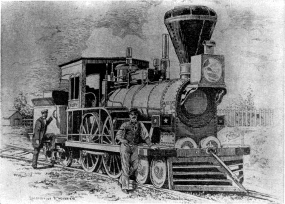 The Fury
The “Fury,” built for the Boston and Worcester Railroad in 1849 by Wilmarth. It was known as a “Shanghai” because of its great height. An American liner, formerly a German ship. She was taken over by the United States during the World ...") The George Washington
The George Washington
An American liner, formerly a German ship. She was taken over by the United States during the World War. he vessel selected for that famous cruise was The Great Balloon of Nassau, then recently built by Mr...") The Great Balloon of Nassau
The Great Balloon of Nassau
he vessel selected for that famous cruise was The Great Balloon of Nassau, then recently built by Mr. Green and representing all that his skill and experience could devise. It was of pear shape, formed of the finest crimson and white silk, “spun, wove and dyed expressly for the purpose,” and comprising when distended a volume of 85,000 cubic feet. From its stout balloon-ring six feet in diameter was suspended a wicker car measuring nine feet long by four wide, having a seat across either end, and a cushioned bottom to serve as a bed, if such should be needed. Across the middle of the car was a plank supporting a windlass for raising or lowering the guide-rope, that is a heavy rope which could be trailed over land, or water, to keep the balloon at a nearly constant level without expenditure of ballast, and to check its speed on landing. This valuable device invented by Mr. Green in 1820, was now to receive adequate trial, which, indeed, formed one of the chief purposes of the cruise. Other paraphernalia of the voyage were food and drink, warm clothing, lamps, trumpets, telescopes, barometers, a quicklime coffee-heater, a grapnel and cable, and a ton of sand ballast in bags. An awkward and unsuccessful ship.
She proved, however, when she was wrecked, that for ship constru...") The Great Britain
The Great Britain
An awkward and unsuccessful ship. She proved, however, when she was wrecked, that for ship construction iron is stronger than wood, and proved, too, that double bottoms, bulkheads, and bilge keels, which were new departures when she was built, were most desirable in ships of her size. A ship that was built half a century too early. This huge vessel, built in 1857, was designed to mak...") The Great Eastern
The Great Eastern
A ship that was built half a century too early. This huge vessel, built in 1857, was designed to make the voyage from England to Australia without refuelling. She never made the voyage to Australia, but was used to lay the Atlantic cable. She was ahead of her time, for engines had not developed to the point where she could be properly propelled. Some of the earliest three-deckers, or, as we may almost call them, five-deckers, were built at this...") The Great Harry
The Great Harry
Some of the earliest three-deckers, or, as we may almost call them, five-deckers, were built at this dockyard; and of these the most famous was the Great Harry, so named after the king, which was launched here in 1514. For the period, the ship was a large one, being of a thousand tons burden; though we should not think much of her size now, when we have ironclads of over eleven thousand tons. There are models of her in the Greenwich Naval Museum, which is not far from Woolwich; and a curious lofty wooden castle she is, rising far up above the water-line, and offering a fair target, if the cannon of those days had any accuracy. Piracy was an everyday occurence for the sailors.") The Gun was disharged
The Gun was disharged
Piracy was an everyday occurence for the sailors.