


 4-Cylinder vertical engine assembly") 4-Cylinder vertical engine assembly
4-Cylinder vertical engine assembly
4-Cylinder vertical engine assembly 4-Cylinder vertical engine assembly") 4-Cylinder vertical engine assembly
4-Cylinder vertical engine assembly
4-Cylinder vertical engine assembly England, in the building and handling of sea-planes has come well to the fore, and our machines are ...") A Bleriot Sea-plane
A Bleriot Sea-plane
England, in the building and handling of sea-planes has come well to the fore, and our machines are more advanced than those of other countries. The Admiralty has recognised that, acting as a coastal scout in time of war, such craft would be of the utmost value; thus we find air-stations dotted round our seaboard, from which machines may fly in a regular patrol. By the employment of hundreds of craft, operating upon a well-ordered plan, it will be possible in the future to girdle our shores completely; and such machines would not only spy out the approach of an enemy’s fleet, but give battle to hostile aeroplanes or airships which might seek to pass inland. The type of machine we have just described was a biplane, but there are monoplane sea-craft, and a Bleriot fitted for alighting upon the water is shown. showing the span of the main-planes, and the curve of the boat-shaped hull.") A Flying Boat
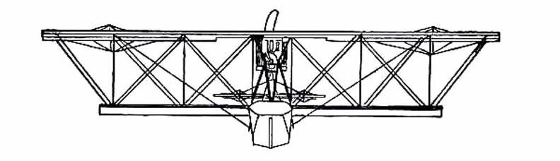
A Flying Boat
showing the span of the main-planes, and the curve of the boat-shaped hull.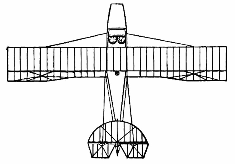
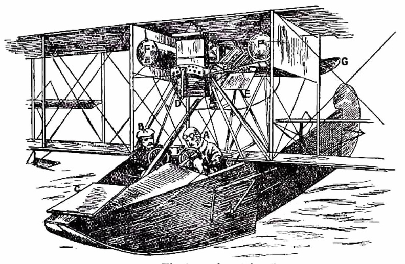
 A. Hull
B. seats for crew
C. Planes
D. Motor
E. Propeller
F. Rudder
G. Elevators.
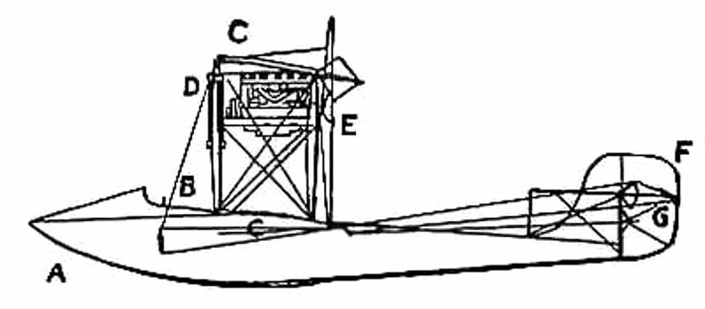
...") A Flying Boat - side view
A Flying Boat - side view
A. Hull B. seats for crew C. Planes D. Motor E. Propeller F. Rudder G. Elevators.
 showing the shape of wings and tail, and the positions of the pilot and passenger within the hull.
...") A Flying Boat top view
A Flying Boat top view
showing the shape of wings and tail, and the positions of the pilot and passenger within the hull.
 German plane crashed into an American warship") A mass of wreckage that strikes the deck of one of our warships
A mass of wreckage that strikes the deck of one of our warships
German plane crashed into an American warship Coal-gas superseded hot air in the filling of balloons, the latter being unsatisfactory, seeing that...") A modern Balloon
A modern Balloon
Coal-gas superseded hot air in the filling of balloons, the latter being unsatisfactory, seeing that it cooled rapidly and allowed the balloon to descend; the only alternative being to do what some of the first aeronauts did, and burn a fire below the neck of their balloon even when in the air. But the dangers of this were great, seeing that the whole envelope might easily become ignited. With balloons filled with coal-gas long flights were possible, but they had always this disadvantage—the voyagers were at the mercy of the wind, and could not fly in any direction they might choose. If the wind blew from the north then they were driven south, the balloon being a bubble in the air, wafted by every gust. Aeronauts became disgusted with this inability to guide the flight of a balloon, and many quaint controls were tested; such, for example, as the use of a large pair of oars with which the balloonist, sitting in the car of his craft, rowed vigorously in the air. One might prefer a single bird, which could be ridden bareback by a man or woman of common equestria...") A possible air-scout
A possible air-scout
One might prefer a single bird, which could be ridden bareback by a man or woman of common equestrian skill. The early philosophers, therefore, sought with some care for such a creature. Air-racing, as made popular by the proprietors of the Hendon aerodrome, forms so fascinating a sight...") A pylon, or mark-tower, on the flying track
A pylon, or mark-tower, on the flying track
Air-racing, as made popular by the proprietors of the Hendon aerodrome, forms so fascinating a sight that, on a day of public holiday, as many as 50,000 people will assemble in the enclosures. To stand near one of the pylons—wooden towers which mark the turning-points of the course—and see the air-racers come rushing by, is to gain such an impression of speed as almost makes the watcher hold his breath. The pilot in a flying race has one chief aim: to fly the shortest way. Every fraction of a second is of importance; and if he can circle the pylons more skilfully than his rivals, he may win the race, even though his machine—in its actual speed—may be no faster than theirs. Ader next turned to steam-driven craft, and built a series of queer, bat-like machines, which he cal...") Ader’s 'Avion'
Ader’s 'Avion'
Ader next turned to steam-driven craft, and built a series of queer, bat-like machines, which he called “Avions,” one of which is illustrated in Fig. 16. Its wings were built up lightly and with great strength by means of hollow wooden spars, and had a span of 54 feet, being deeply arched. The whole machine weighed 1100 lbs., and was thus far smaller and lighter than Maxim’s mighty craft. To propel it, Ader used a couple of horizontal, compound steam engines, which gave 20 h.p. each and drew the machine through the air by means of two 4-bladed screws. The craft was controlled by altering the inclination of its wings, and also by a rudder, the pilot sitting in a carriage below the planes. In 1890, after its inventor had spent a large sum of money, the machine—which, unlike those of Phillips and Maxim, ran upon wheels and was free to rise—did actually make a flight, or rather a leap into the air, covering a distance of about fifty yards. But then, on coming into contact with the ground again, it was wrecked. Ader’s experiments were regarded by the French Government as being so important that he received a grant equalling £20,000 to assist him in continuing his tests; and this goes to show how, even from the first, the French nation was—by reason of its enthusiasm and imagination—able to appreciate what its inventors were striving to attain, and eager to encourage them in their quest. Airships, like aeroplanes, are being armed with guns and bombs; and their power of raising weights e...") Aeroplanes attacking an airship from above
Aeroplanes attacking an airship from above
Airships, like aeroplanes, are being armed with guns and bombs; and their power of raising weights enables them to carry heavy weapons. Large and highly destructive bombs have been tested in the German airships, being released over the sea and aimed at targets in the form of rafts. Latest-type airships also carry guns in their cars; and the Zeppelins have a platform upon the tops of their hulls, reached by a ladder through the middle of the ship, from which a machine-gun can be fired upward. This is a very necessary precaution, and is intended to frustrate the attack of an aeroplane. It would be the aim of the latter, whenever possible, to manœuvre above its big enemy—as suggested in figure —and drop a bomb upon its hull. Hence the construction of the top platform of the airship, from which her gunners can direct a vigorous fire aloft. By the use of such a machine as this, twenty years hence, we shall be able to spend a week-end in Ne...") Airliners of the future
Airliners of the future
By the use of such a machine as this, twenty years hence, we shall be able to spend a week-end in New York, as we do now in Paris or Scotland. Flying at immense heights, and at speeds of 200 miles an hour, these huge aircraft—carrying hundreds of passengers in vibrationless luxury—will pass from London to New York in less than twenty hours. An aeroplane is a necessity in times of peace") An aeroplane is a necessity in times of peace
An aeroplane is a necessity in times of peace
An aeroplane is a necessity in times of peace An aeroplpane in war") An aeroplpane in war
An aeroplpane in war
An aeroplpane in war An Airship leaving its shed
A. The machine emerging stern first
B. A sister craft in dock
C. Th...") An Airship leaving its shed
An Airship leaving its shed
An Airship leaving its shed A. The machine emerging stern first B. A sister craft in dock C. The launching crews D. Rails upon which the cars of the airship move, so as to prevent its swinging sideways in a gust E. Outlook station upon the roof of the shed F. Workshops; living quarters for the crews; plant for making hydrogen gas. The sea-plane, when a flight is made, is launched upon the water down a slipway; then the pilot and ...") An Avro Sea-Plane
An Avro Sea-Plane
The sea-plane, when a flight is made, is launched upon the water down a slipway; then the pilot and his passenger embark, the motor is started, and the propeller draws the machine across the water at a rapidly increasing pace. The floats raise themselves higher and higher upon the water, as the air-planes exercise a growing lift, until they only just skim the surface. And now comes the moment when the airman, drawing back his elevating lever, seeks to raise his craft from the water into the air. At first only the front of the floats rise, the rear sections clinging to the surface; then, in another instant, the whole float frees itself from the water in a scatter of spray, and the craft glides at a gently-sloping angle into the air. It is the aim of builders, by the curve they impart, to make the floats leave the water with as little resistance as possible. In the floats of the Avro will be noticed a notch, or cut-away section, which occurs at about the centre of the float upon its lower side. This is called a “step,” and is to help the float to lift from the water. When the main-planes draw upward, as the craft moves prior to its flight, the floats tend, as has been said, to raise themselves in the water; and as they do so, lifting first towards the bow, there comes a space between the upward-cut “step” and the surface of the water. Into this space air finds its way and, by helping still further to free the float from the surface, aids greatly at the moment when the pilot—operating his hand-lever—seeks the final lift which will carry him aloft. A. Propeller B. 100-h.p. Gnome motor, hidden by shield C. Main-planes D. Observer’s seat E. Pilot’s seat F. Rudder G. Elevating-plane H. Float to support tail I. Main floats to bear the weight of the machine. ...it was followed in due course by the use of small steam engines and electric motors, which were ...") An Experimental Airship
An Experimental Airship
...it was followed in due course by the use of small steam engines and electric motors, which were made to turn propellers such as are used in aeroplanes. For such experimental craft, the rounded form of gas-container was abandoned and a cigar-shaped envelope adopted, pointed at both ends, which could be more easily driven through the air. An airship of a crude and early type is seen here. It was built by an experimenter named Gifford, and in 1852 it flew at the rate of seven miles an hour. A. Gas-containing envelope; B. Car suspended below envelope, which carried the aeronaut and a 3-horse-power steam engine; C. Two-bladed propeller driven by the engine; D. Rudder (in the form of a sail) by which the machine could be steered from side to side. Aviators taking photographs") Aviators taking photographs
Aviators taking photographs
Aviators taking photographs") Banked turn on a biplane
Banked turn on a biplane Battle between aeroplane and British tank") Battle between aeroplane and British tank
Battle between aeroplane and British tank
Battle between aeroplane and British tank Battleplanes convoying photographing aeroplanes") Battleplanes convoying photographing aeroplanes
Battleplanes convoying photographing aeroplanes
Battleplanes convoying photographing aeroplanes Beech AT-10
Front Side
Perspective
Bottom ...") Beech AT-10
Beech AT-10
Beech AT-10 Front Side Perspective Bottom Top Beech AT-11
Front Side
Perspective
Bottom ...") Beech AT-11
Beech AT-11
Beech AT-11 Front Side Perspective Bottom Top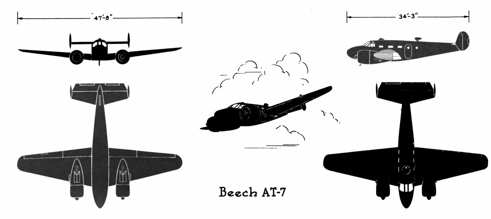 Beech AT-7
Beech AT-7 Front Side Perspective Bottom Top (1492 visits) Beech C-45 (F-2)
Front Sid...") Beech C-45 (F-2)
Beech C-45 (F-2)
Beech C-45 (F-2) Front Side Perspective Bottom Top Bell P-39C & D
Front Side ...") Bell P-39C & D
Bell P-39C & D
Bell P-39C & D Front Side Perspective Bottom Top In 1678, Besnier, a French locksmith, constructed a curious flying machine consisting of two wooden ...") Besnier and his wings
Besnier and his wings
In 1678, Besnier, a French locksmith, constructed a curious flying machine consisting of two wooden bars which rested on his shoulders. At the ends of the bars he attached muslin wings, arranged to open on the down stroke and close on the up stroke. The wings were operated by moving the arms and legs. Although Besnier failed to realize that no man had sufficient muscular strength to fly as the bird flies, he did sense part of the truth—that gliding with the air currents was possible. During his experiments he is said to have jumped from a window sill, glided over the roof of a near-by cottage, and landed on a barge in the river. Of the devices suggested [for man to fly] many showed ingenuity; and some were quaint, in view of ...") Besnier’s Apparatus
Besnier’s Apparatus
Of the devices suggested [for man to fly] many showed ingenuity; and some were quaint, in view of what we know of flight to-day. In the machine, for instance, designed by an experimenter named Besnier—who was a locksmith by trade—there were four lifting planes, closing on the up-stroke and opening on the down, and these the operator was to flap by the use of his hands and feet. Biplane") Biplane
Biplane
Biplane The first attempts at balloon propulsion could not be seriously regarded by trained engineers, even ...") Blanchard’s dirigible balloon, 1784
Blanchard’s dirigible balloon, 1784
The first attempts at balloon propulsion could not be seriously regarded by trained engineers, even at the inception of aëronautics; but still, as infantile steps in the new art, they may deserve passing notice. Blanchard, on March 2, 1784, made the first real effort to steer a balloon, using for that purpose a spherical gas bag and car provided with aërial oars and a rudder. As he was about to ascend, however, from the Champs de Mars, a young officer with drawn sword persisted in accompanying the pilot, thus compelling Blanchard to leave his wings on earth to allow sufficient buoyancy for himself and his obtrusive guest. His first trial was, therefore, frustrated; but subsequent ones made with that inadequate contrivance also proved futile under the best circumstances; for the scheme was evidently puerile, though tried by various grown-up men besides M. Blanchard. One of the earliest authenticated devices of this kind was the invention of Blanchard, described by ...") Blanchard’s flying-machine
Blanchard’s flying-machine
One of the earliest authenticated devices of this kind was the invention of Blanchard, described by him in the Journal de Paris, August 28, 1781, nearly two years before the invention of the hot-air balloon, of which he became later an enthusiastic votary. As his device is but one of a large number that appeared before the close of the nineteenth century, and the advent of light motors, the reader who wishes fuller acquaintance with man-driven airships may be referred to Mr. Chanute’s book, entitled Progress in Flying-Machines, which describes a large variety of such inventions, and discusses the merit and weakness of each. Blériot would improve that record at once, by flying in a closed circuit embracing several villages...") Blériot’s Toury-Artenay aëroplane circuit, 1908
Blériot’s Toury-Artenay aëroplane circuit, 1908
Blériot would improve that record at once, by flying in a closed circuit embracing several villages. His renowned cross-country flight was directed from Toury to Artenay, a village nine miles distant. Mounting his aëroplane VIII-ter, at mid afternoon, in presence of a large gathering, Blériot followed the course shown. In the neighborhood of Artenay he landed for a few minutes. After some slight repairs to his magneto, he reascended, turned about and headed for home. Half way on his return course he stopped again for a few minutes, at the Village of Santilly; then readily reascended and flew to the neighborhood of his starting point. He thus traveled about 17 miles in a closed circuit. This performance, with that of Farman the day before, inaugurated the period of aërial voyages in heavier-than-air machines. Blimp bombing a submarine") Blimp bombing a submarine
Blimp bombing a submarine
Blimp bombing a submarine Boeing B-17E
Front Side
...") Boeing B-17E
Boeing B-17E
Boeing B-17E Front Side Perspective Bottom Top A. Lower part of aeroplane’s hull
B. Revolving barrel to which bombs are clipped
C. Bombs
D. Re...") Bomb-releasing mechanism
Bomb-releasing mechanism
A. Lower part of aeroplane’s hull B. Revolving barrel to which bombs are clipped C. Bombs D. Releasing mechanism operated by marksman in machine. Bombs may be carried and dropped when opportunity offers; and as an improvement upon the early method, which was simply to throw these from the machine, there are releasing mechanisms now devised which carry a number of projectiles and drop them one by one as a lever is moved. The bombs, which are long, pointed, and balanced so that they will fall head first, are clipped round a barrel rather like that of a revolver, which is fixed beneath the aeroplane’s hull just below the occupants’ seat. Mechanism causes the carrying chamber to revolve and bring each bomb against a releasing catch, which—at a movement of the marksman’s lever—throws it outwards and downward. A still more elaborate and colossal air ship was the Geant, constructed in 1863, for A. Nadar of Par...") Car of Nadar’s balloon
Car of Nadar’s balloon
A still more elaborate and colossal air ship was the Geant, constructed in 1863, for A. Nadar of Paris. It was made of a double layer of white silk, had a volume of 215,000 cubic feet and a buoyancy of 4½ tons. The car was a wicker cabin 13 feet wide by 7 feet high, with a wicker balcony round the top so that the roof could be used as an observation deck—a delightful place to loll in the starlight, or watch the morning sun “flatter the mountain tops with sovereign eye.” The closed car comprised two main rooms with a hallway between them, one containing the captain’s bed and baggage, the other having three superposed berths for passengers. Minor divisions of the car were reserved for provisions, a lavatory, photography and a printing press, the latter to be used for the dissemination of news from the sky, as the navigators floated from state to state. A compensator balloon of 3,500 cubic feet, just below the main bag and connected with it, received the escaping gas during expansion with increase of tempera61ture or altitude, and gave it back on contraction. Cessna AT-8
Front Side
...") Cessna AT-8
Cessna AT-8
Cessna AT-8 Front Side Perspective Bottom Top The ascent of this, the first hydrogen balloon, was a popular and a memorable event. The field was l...") Charles’ first hydrogen balloon
Charles’ first hydrogen balloon
The ascent of this, the first hydrogen balloon, was a popular and a memorable event. The field was lined with troops. The curious spectators had thronged every thoroughfare and darkened every housetop. It was an all day festival, inaugurating a peculiarly French science, with French animation. The booming of cannon announced to all Paris the impending flight of the balloon. At five o’clock, in the presence of 50,000 spectators, and in a shower of rain, the balloon rose more than half a mile and entered the clouds. The people overwhelmed with surprise and enthusiasm, stood gazing upward, despite the rain, observing every maneuver till the vessel had ascended and faded from view. This balloon was a truly scientific creation, which advanced aërostation from tottering infancy alm...") Charles’ passenger balloon
Charles’ passenger balloon
This balloon was a truly scientific creation, which advanced aërostation from tottering infancy almost to full prime. The bag was a sphere 27½ feet in diameter made of gores of varnished silk. A net covered the upper half and was fastened to a horizontal hoop girding the middle of the globe, and called the “equator.” From the equator depended ropes which supported, just below the spherical bag, a wicker boat measuring eight feet by four, covered with painted linen and beautifully ornamented. The balloon had at the bottom a silk neck 7 inches in diameter, to admit the gas during inflation, and at the top, a valve which could be opened by means of a cord in the boat to let out gas during a voyage, so as to lower the balloon, or to relieve excessive pressure. In the boat were carried sand ballast to regulate the height of ascension, a barometer to measure the elevation, anchor and rope for landing, a thermometer, notebook, provisions, and all the paraphernalia of a scientific voyage. Barring the fancy boat, this is almost a description of a good modern balloon. In outward appearance the Clément-Bayard II closely resembled her predecessor, except for the absen...") Clément-Bayard II, 1910
Clément-Bayard II, 1910
In outward appearance the Clément-Bayard II closely resembled her predecessor, except for the absence of empennage on her envelope. In the whalelike elegance of her hull she was, in fact, a reversion to the trim and efficient model of Renard’s dirigible of 1884, which in turn was a fair copy of Jullien’s model of 1850, all having excellent forms for speed and stability. But the new vessel was of greater size and power than her predecessor. Her net buoyancy was sufficient to carry twenty passengers. Her average speed tested in a round-trip voyage was about 50 kilometers or 31 miles per hour when her two motors developed 200 horse power, and 55 kilometers or 34 miles per hour when the engines developed their maximum effort of 260 horse power. Consolidated B-24 D & E
Front &n...") Consolidated B-24 D & E
Consolidated B-24 D & E
Consolidated B-24 D & E Front Side Perspective Bottom Top Consolidated OA-10
Front S...") Consolidated OA-10
Consolidated OA-10
Consolidated OA-10 Front Side Perspective Bottom Top") Construction of a Monoplane wing
Construction of a Monoplane wing A. Wheels operating elevating-planes and rudder
B. Height recorder
C. Speaking-tube to communicate...") Control platform of an Airship
Control platform of an Airship
A. Wheels operating elevating-planes and rudder B. Height recorder C. Speaking-tube to communicate with engineers. Curtis O-52
Front Side
...") Curtis O-52
Curtis O-52
Curtis O-52 Front Side Perspective Bottom Top Curtis P-36C
Front Side
...") Curtis P-36C
Curtis P-36C
Curtis P-36C Front Side Perspective Bottom Top Curtiss AT-9
Front Side
...") Curtiss AT-9
Curtiss AT-9
Curtiss AT-9 Front Side Perspective Bottom Top Curtiss C-46
Front Side
...") Curtiss C-46
Curtiss C-46
Curtiss C-46 Front Side Perspective Bottom Top Curtiss P-40E
Front Side
...") Curtiss P-40E
Curtiss P-40E
Curtiss P-40E Front Side Perspective Bottom Top Biplane (540 visits) A. Hull, which is steel-built, containing pilot and passenger
B. Main-planes—the lower at a dihed...") D.F.W. (German-designed) Biplane
D.F.W. (German-designed) Biplane
A. Hull, which is steel-built, containing pilot and passenger B. Main-planes—the lower at a dihedral angle C. Uptilted stabilising ailerons, which may be locked in position D. Stabilising fin E. Rudder F. Elevating-plane G. 100-h.p. motor (which is enclosed) and propeller. Leonardo da Vinci, who was a gifted engineer as well as an artist, devised a flying gear for man whi...") Da Vinci’s designs for human flying-gear
Da Vinci’s designs for human flying-gear
Leonardo da Vinci, who was a gifted engineer as well as an artist, devised a flying gear for man which shows some dynamic improvement over the mechanism of the old-time angels, flying gods, and hobgoblins. As shown in the accompanying sketch, it provided for gravitational balance by use of an expanding tail projecting well to the rear. Moreover, the propulsion was to employ both arms and legs. This design is considered very remarkable for the time in which it was produced, probably a few years before the discovery of America; and yet it is but one of Da Vinci’s quaint aëronautical inventions, as will appear later. Da Vinci’s second flyer was a helicopter. An aërial screw 96 feet in diameter was to be turned by...") Da Vinci’s helicopter
Da Vinci’s helicopter
Da Vinci’s second flyer was a helicopter. An aërial screw 96 feet in diameter was to be turned by a strong and nimble artist who might, by prodigious effort, lift himself for a short time. Though various small paper screws were made to ascend in the air, the larger enterprise was never seriously undertaken. Many subsequent inventors developed the same project; but the fellow turning the screw always found it dreadful toil and a hopelessly futile task. Of late the man-driven helicopter has been abandoned, but the motor-driven one is very much cultivated. Scores of inventors in recent years, aided by light motors, have been trying to screw boldly skyward, and some have succeeded in rising on a helicopter carrying one man. Da Vinci’s third scheme for human flight, was a framed sail on which a man could ride downward, if...") Da Vinci’s parachute
Da Vinci’s parachute
Da Vinci’s third scheme for human flight, was a framed sail on which a man could ride downward, if not upward. This device never fails to navigate with its confiding sailor. Sometimes he lands in one posture, again in another; but voyage he must, with the certainty of gravitation. Leonardo is, therefore, the father of the parachute. This, in turn, has had a varied offspring. The common parachute, the aërial glider, the soaring machine, or passive aëroplane, that rides the wind without motive power and without loss of energy. The story of Dædalus and Icarus also tells us that man believed flying was somehow possible. Dædal...") Daedalus and Icarus
Daedalus and Icarus
The story of Dædalus and Icarus also tells us that man believed flying was somehow possible. Dædalus was a very clever man who lived with his son Icarus on the Island of Crete. The king of this island requested Dædalus to build a labyrinth or maze for him. Dædalus constructed the labyrinth so cleverly that only the king, who had the clue to the winding passages, could find his way out. One day the king became very angry at Dædalus and threw both him and his son Icarus into the labyrinth, intending that they should perish. Dædalus, who had been dreaming of flying, fashioned wings from wax and feathers, with which he and Icarus could fly to freedom. He cautioned Icarus that he must not fly too high or the sun would melt the wax in his wings. Icarus, impatient to escape, scarcely listened. Like birds the two flew into the air, quickly leaving the walls of the labyrinth. Dædalus, flying low, safely crossed the sea and reached Sicily. Icarus, unfortunately, failed to heed his father’s warning. Flying was so much fun that he rose higher and higher. Suddenly feathers began to drop one by one. Too late Icarus realized that the sun had melted the wax in his wings. Down, down he fell into the sea. A method of flying was suggested as long ago as 1744, by the inventor De Bacqueville; his plan was ...") De Bacqueville
De Bacqueville
A method of flying was suggested as long ago as 1744, by the inventor De Bacqueville; his plan was to fix four planes or wings to his hands and feet, and then propel himself through the air by vigorous motions of his arms, and kickings of his legs. He made a flight from a balcony overlooking a river, but finished his trial ingloriously by falling into a barge. Such schemes, indeed, were doomed to failure; and they are only interesting because they show how, even in those far-off days, men were ready to risk their lives in attempts to conquer the air. The ripping panel, invented in 1844 by America’s foremost pioneer aëronaut, John Wise, is a simpl...") Diagram of a modern spherical balloon with ripping panel
Diagram of a modern spherical balloon with ripping panel
The ripping panel, invented in 1844 by America’s foremost pioneer aëronaut, John Wise, is a simple and an excellent practical device. This is a long patch running longitudinally above the equator[8] of the balloon, feebly sewed to the envelope, and having a cord, called the “ripping cord,” extending down to the car along the outside or inside of the bag, so that the pilot on coming to earth can let out the gas quickly by tearing a rent in the balloon, thus flattening it promptly on the earth’s surface, so as to avoid dragging and bumping if any wind prevails. 1. Motor; 2. Radiator; 3. Fuel Tank; 4. Upper Main Plane; 5. Lower Main Plane; 6. Aileron; 7. Vertic...") Diagram of Curtiss Aeroplane, side view
Diagram of Curtiss Aeroplane, side view
1. Motor; 2. Radiator; 3. Fuel Tank; 4. Upper Main Plane; 5. Lower Main Plane; 6. Aileron; 7. Vertical Rudder; 8. Tail Surface; 9. Horizontal Rudder, or Rear Elevator; 10. Front Elevator; 11. Vertical Fin; 12. Steering Wheel; 13. Propeller; 14. Foot Throttle Lever; 15. Hand Throttle Lever; 16. Foot Brake.") Diagram of Curtiss hydro-aëroplane
Diagram of Curtiss hydro-aëroplane 1. Cylinder; 2. Engine Bed; 3. Fuel Tank: 4. Oil Pan; 5. Radiator; 6. Propeller; 7. Crank Case; 8. C...") Diagram of Curtiss motor, side and front views
Diagram of Curtiss motor, side and front views
1. Cylinder; 2. Engine Bed; 3. Fuel Tank: 4. Oil Pan; 5. Radiator; 6. Propeller; 7. Crank Case; 8. Carbureter; 9. Gasoline Pipe; 10. Air Intake; 11. Auxiliary Air-pipe; 12. Drain Cock; 13. Water Cooling System; 14. Gas Intake Pipe; 15. Rocker Arm; 16. Spring on Intake Valve; 17. Spring on Exhaust Valve; 18. Exhaust Port; 19. Rocker Arm Post; 20. Push Rod.