


") Workman fashioning a spectacle lens
Workman fashioning a spectacle lens The article upon the Velocipede in the \" American Encyclopedia,\" commences by giving the well-known ...") Velocipedes
Velocipedes
The article upon the Velocipede in the " American Encyclopedia," commences by giving the well-known derivation of the word from the Latin velox, swift, and pes, a foot, and defines it as a carriage, by means of which the rider propels himself along the ground, and states that it was invented at Manheim. We present a bicycle for ladies, lately invented and patented by Messrs. Pickering & Davis of New Yo...") Velocipede for Ladies
Velocipede for Ladies
We present a bicycle for ladies, lately invented and patented by Messrs. Pickering & Davis of New York City. It will be seen that the reach or frame, instead of forming a nearly straight line from the front swivel to the hind axle, follows the curve of the front wheel until it reaches a line nearly as low as the hind axle when it runs horizontally to that point of the hind wheel. The two wheels being separated three or four inches, allow of an upright rod being secured to the reach; around this is a spiral spring, on which a comfortable, cane-seated, willow-backed chair is placed. This machine, with a moderate-sized wheel (of thirty to thirty-three inches), will allow being driven with a great deal of comfort and all the advantages of the two-wheel veloce. In mounting, a lady has to step over the reach, at a point only twelve inches from the floor, the height of an ordinary step in a flight of stairs.") Tycho Brahe's House and Observatory
Tycho Brahe's House and Observatory There needs to be an equipment of spare machines also; and a number of travelling workshops with ski...") Travelling workshop for the repair of military aeroplanes
Travelling workshop for the repair of military aeroplanes
There needs to be an equipment of spare machines also; and a number of travelling workshops with skilled engineers, which can be rushed from place to place for the repair of damaged craft. A sketch of one of these workshops on wheels, which are vital to the organisation, is seen in the figure The Voisin Biplane - top view") The Voisin Biplane - top view
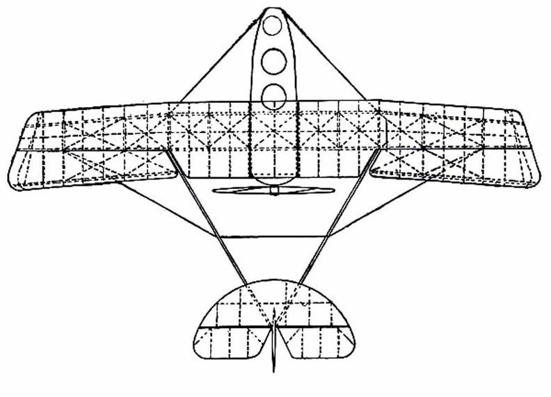
The Voisin Biplane - top view
The Voisin Biplane - top view At the beginning of 1909 there were two types of successful aeroplane—the Wright and the Voisin. B...") The Voisin Biplane
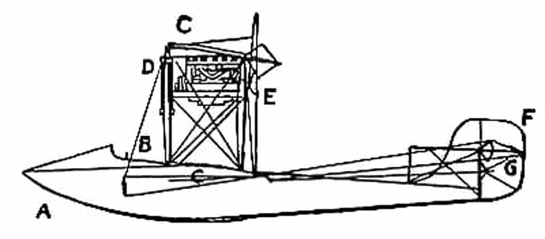
The Voisin Biplane
At the beginning of 1909 there were two types of successful aeroplane—the Wright and the Voisin. Bleriot had flown with his monoplane and flown well; but he was still in the process of evolving a practical machine, and several other inventors were in a similar stage. It was the Wright and the Voisin which had proved their worth; and the Wright, as has been said, was the better of the two. Of the Voisin, as flown in 1909, a reproduction is given in the figure. It was a heavier aeroplane than the Wrights’, owing largely to the weight of its alighting gear (250 lbs.) and of its big balancing tail (more than 100 lbs.); hence the necessity for using a 50-h.p. motor, which drove a two-bladed metal propeller at the rate of 1200 revolutions a minute. The Voisin brothers, and other French makers, did not approve of the two-propeller system of the Wrights: they preferred one screw, revolving at high speed. But there was no doubt—at any rate in this stage of aviation—that the Wright method was more efficient than that of the Frenchmen. It was calculated, indeed, that the Wright biplane, when actually in the air, could be driven at an expenditure of only 15 h.p.; whereas the Voisin, even with its 50-h.p. motor running at full speed, had only just enough power to fly. A. Elevating plane B. Pilot’s seat C.C. Main-planes D. Engine and propeller E. Landing chassis F. Balancing tail G. Rudder. Already, anticipating war in the air, a fighting aeroplane has been evolved; and a machine of this t...") The Vickers
The Vickers
Already, anticipating war in the air, a fighting aeroplane has been evolved; and a machine of this type is shown in Figure. The body, in which pilot and gunner sit, is armoured lightly with plates which will resist the penetration of a bullet. Such armouring was found necessary after the use of aeroplanes in Tripoli and the Balkans. When flying unavoidably low in these campaigns, and when fired at from the ground, the wooden bodies of machines were pierced by shot, and in several instances their occupants wounded. A fighting aeroplane A. Machine-gun projecting from opening in bow B. Gunner’s position C. Pilot’s seat D.D. Side windows for observation E. Engine and propeller. A. Enclosed body
B. Driver’s position
C. Steering wheel
D. Foot-controlled throttle lever for e...") The single-seated 'air-car'—a suggested type
The single-seated 'air-car'—a suggested type
A. Enclosed body B. Driver’s position C. Steering wheel D. Foot-controlled throttle lever for engine E.E. The two sustaining-planes F. The motor G. Propeller H. Rudder I. Elevating-plane J. Landing gear. First probably for mails, and after this for passenger-carrying, will aeroplanes of the future be employed; and they will find a scientific use, too, in exploring remote corners of the earth, and in passing above forests which are now impenetrable. Small, fast machines, much cheaper than those of to-day, will be bought also for private use—many of them, as suggested by the figure, having room for only one man within their hulls. Then there will be flying clubs; and to these, after their day’s work, will come a city’s toilers. Through the cheapening of craft, as time goes on, practically all members of the community will experience the joys of flight. Thus, say on a summer’s evening, the doors of the sheds will be pushed aside, and the machines wheeled out and overhauled; then, one by one, these small, fast-moving craft will rise into the air and dart here and there—circling, manœuvring, dipping, and diving. The difficulty with air-cooling—although it had obvious advantages over water-cooling—was to bri...") The seven-cylinder 50-h.p. Gnome motor.
The seven-cylinder 50-h.p. Gnome motor.
The difficulty with air-cooling—although it had obvious advantages over water-cooling—was to bring enough air to play upon the surfaces of the cylinders; and it was here that the Gnome won so complete a success. In other engines the cylinders were stationary, and their pistons, moving up and down in the cylinders, turned a crank-shaft to the end of which the propeller was fixed. Therefore the only air the cylinders obtained was what rushed upon them through the speed of the machine in flight. But in the Gnome, instead of the cylinders remaining stationary and the crank-shaft revolving, the cylinders themselves spun round, and the crank-shaft did not move. An illustration of this motor with one end of the crank-chamber removed, so that the piston-rods can be seen, is given in the figure. It will be noted that there are seven cylinders, set in the form of a star, and that the seven piston-rods projecting from them come together upon a single crank-pin, which is attached to the stationary crank-shaft and turns round it. The propeller, instead of being fitted to the crank-shaft, as was the case with other motors, was bolted to a plate upon the engine itself, so that when this turned around its crank-shaft, it carried the propeller with it.") The Screw of Archimedes
The Screw of Archimedes An experimenter who braved this apathy and won his way until he became a constructor of aircraft, wa...") The Roe Triplane
The Roe Triplane
An experimenter who braved this apathy and won his way until he became a constructor of aircraft, was Mr. A. V. Roe. For some time he was an advocate of the triplane form of machine—a craft, that is to say, with three main-planes fitted one above another. The machine with which he obtained flights, although they were very brief, is seen in the figure. Subsequently, however, Mr. Roe adopted the biplane form. His distinction in the pioneer days was that he managed to make his triplane lift into the air and fly a short distance, with the aid of a motor-cycle engine developing no more than 9 h.p. A.A.A. Three main-planes B. Motor C. Four-bladed propeller D.D.D. Triplane tail E. Rudder F. Landing gear.") The Present Aspect of Constantinople
The Present Aspect of Constantinople") The Magdeburg Experiment on the Large Scale
The Magdeburg Experiment on the Large Scale A. Pilot’s seat and controlling wheel
B. Passenger’s seat
C. Movable flap to facilitate enteri...") The hull of a Flying-Boat
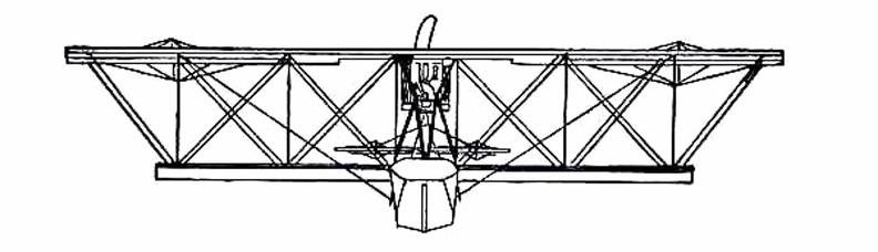
The hull of a Flying-Boat
A. Pilot’s seat and controlling wheel B. Passenger’s seat C. Movable flap to facilitate entering the hull D. Handle, like that of a car, for starting the engine E. The engine F. Fuel tanks G. The propeller.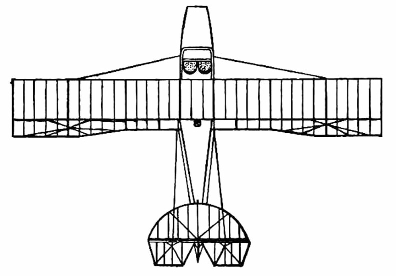
") The Giralda at Seville
The Giralda at Seville showing the span of main-planes, elevator, and tail, also the positions of landing gear and pilot’...") The Farman Biplane - top view
The Farman Biplane - top view
showing the span of main-planes, elevator, and tail, also the positions of landing gear and pilot’s seat.
In July, at Rheims, there was to be the great flying meeting; and Farman had made up his mind to...") The Farman Biplane
The Farman Biplane
In July, at Rheims, there was to be the great flying meeting; and Farman had made up his mind to wait for this. Aided by the experience he had gained with the Voisin machine, he had designed a craft which should be generally more efficient and faster in flight, and more quickly responsive to its controls. The biplane he produced, marking as it did a step forward in construction, is a machine that needs description. The general appearance of the craft is indicated by Fig. 46, while an illustration of this type of machine in flight will be found on Plate VII. A feature of the Voisin that Farman discarded was the vertical panel fitted between the main-planes to give sideway stability. An objection to these planes was that they added to the weight of the machine and checked its speed, tending also to drive it from its course should there be a side wind. But in taking away such fixed balancing-planes, Farman had to substitute another device; and what he did was to work upon the same theory as the Wrights had done, and obtain a similar result in a different way. They, it will be remembered, had warped the rear portions of their main-planes. Farman kept his planes rigid, but fitted to their rear extremities four narrow, hinged planes, or flaps, which could be moved up and down and were called ailerons. Their effect was the same as with the Wright wing-warp. When a gust tilted the machine, the pilot drew down the ailerons upon the side that was inclined downward; whereupon the air-pressure, acting upon the drawn-down surfaces, restored the machine to an even keel. A. Elevating-plane; B.B. Main-planes; C. Pilot’s seat; D. Motor and propeller; E. Petrol tank; F.F. Hinged balancing-planes, or ailerons; G.G. Tail-planes; H.H. Twin vertical rudders; I. Landing wheels and skid The Curtiss Biplane making a turn") The Curtiss Biplane making a turn
The Curtiss Biplane making a turn
The Curtiss Biplane making a turn The Curtiss Biplane in flight") The Curtiss Biplane in flight
The Curtiss Biplane in flight
The Curtiss Biplane in flight showing the chassis and the position between the planes of the two ailerons (A.A.).") The Curtiss Biplane front view
The Curtiss Biplane front view
showing the chassis and the position between the planes of the two ailerons (A.A.). Of famous aeroplanes at Rheims, five types stood out by themselves—the Farman, the Voisin, the Wri...") The Curtiss Biplane
The Curtiss Biplane
Of famous aeroplanes at Rheims, five types stood out by themselves—the Farman, the Voisin, the Wright, the Bleriot, and the Antoinette, all of which have been described. But there was one other, which few people had heard of before it appeared here. This was the Curtiss biplane, built by an American named Glenn H. Curtiss, and engined with a motor which also bore his name. Curtiss had experimented with many power-driven machines—motor-cycles, motor-cars, airships, and aeroplanes—and had won a prize in America with a small, light biplane, and it was a craft of this type—as seen in the figure —that he brought with him to Rheims, his idea being to compete for the speed prize. The machine had a front elevator and tail-planes, according to the practice in biplane construction; but an innovation was the setting of the ailerons midway between the main-planes—a position that will be noted in the sketch; another novelty was the way these ailerons operated. At the pilot’s back, as he sat in his driving seat, was an upright rod with two shoulder-pieces—by means of which, should he shift his body, he could swing the rod from side to side. Wires ran from the rod to the ailerons; and if the pilot leaned over, say, to the right, he drew down the ailerons on the left side of the machine. The merit of such a control was that it was instinctive; that is to say, should the biplane tip down on one side, it was natural for the pilot to lean away from the plane-ends that were sinking; and he operated the ailerons automatically, as he did this, and so brought the machine level again. A. Elevating-planes B. Pilot’s seat and control-wheel C.C. Main-planes D. Ailerons E. Motor and propeller F. Tail-plane and rudder. showing the large size of the elevators, the position of the pilot, and the placing of the propeller...") The Cody Biplane from above
The Cody Biplane from above
showing the large size of the elevators, the position of the pilot, and the placing of the propellers. Another ardent worker in England, and one destined to become famous, was Mr. S. F. Cody. After devel...") The Cody Biplane
The Cody Biplane
Another ardent worker in England, and one destined to become famous, was Mr. S. F. Cody. After developing a system of man-lifting kites which the British War Office acquired, he joined the military aircraft factory that had been established at Farnborough. Here, after tests with dirigible balloons, he began the construction of experimental biplanes—all machines of large size. Early in 1909 he made brief flights—the longest being one of about 250 yards. Then, after alterations to his machine, he managed in July to fly a distance of 4 miles. This he increased afterwards to 8 miles; and then on 1st September flew for 1 hour 3 minutes, rising to a height of 300 feet. Cody’s biplane was a very large machine, having 1000 square feet of lifting surface—twice that of the Farman or Voisin. Driving it was an 80-h.p. engine, which operated two propellers on the system used by the Wrights. With its pilot on board the machine weighed 2170 lbs. A. Elevating-planes and vertical-plane B. Pilot’s control lever C.C. Main-planes D. Motor E. Propellers F. Rudder G. Landing gear H. Rear skid.") The Cathedral of Amiens
The Cathedral of Amiens A.A. Ballast bags filled with sand
B. Instruments (such as a statoscope, which shows at any moment ...") The car of a modern Balloon
The car of a modern Balloon
A.A. Ballast bags filled with sand B. Instruments (such as a statoscope, which shows at any moment whether the balloon is rising or falling; and an altitude meter) C. Ring by which car is attached to balloon. The Bleriot Monoplane - top view showing its bird-like shape and the position of the pilot.") The Bleriot Monoplane - top view
The Bleriot Monoplane - top view
The Bleriot Monoplane - top view showing its bird-like shape and the position of the pilot. A. Propeller
B. Motor
C. Sustaining-plane
D. Pilot’s seat
E. Landing chassis
F. Combined tail...") The Bleriot Monoplane
The Bleriot Monoplane
A. Propeller B. Motor C. Sustaining-plane D. Pilot’s seat E. Landing chassis F. Combined tail and elevating-planes G. Rudder. Of the various kinds of velocipedes, four, three, two, and one wheeled, the bicycle seems to be cons...") The Bicycle
The Bicycle
Of the various kinds of velocipedes, four, three, two, and one wheeled, the bicycle seems to be considered the most artistic, is altogether the most in favor, and steadily maintains its ground against all rivals. Whether it will be the model velocipede of the future remains to be seen. The various experiments now being tried will, no doubt, eventually result in a nearly perfect machine, but it will require a season's experience fully to develop the ingenuity of our American artisans. Many have expressed doubts as to the real utility of the velocipede, and the permanency of its use. They seem to think it a frivolous invention only calculated to serve purposes of amusement, and soon to be superseded by some other ephemeral claimant for popularity. Most of these have based their opinions upon the disuse into which rude machines have fallen in former times. But the difference in the construction of the modern velocipede from the primitive one has entirely changed the character of the vehicle. It is no longer a draft vehicle, but a locomotive, and as much superior to the original bar on wheels, as the improved steam locomotive is to the old-time stage-coach. showing the spread of the planes and tail, and the delicate taper of the long, canoe-shaped body.") The Antoinette Monoplane - top view
The Antoinette Monoplane - top view
showing the spread of the planes and tail, and the delicate taper of the long, canoe-shaped body. At the beginning of 1909 a new monoplane made its appearance in France—a powerful, finely construc...") The Antoinette Monoplane
The Antoinette Monoplane
At the beginning of 1909 a new monoplane made its appearance in France—a powerful, finely constructed, and very stable machine. It was the Antoinette, designed by a famous engineer, and it was this craft which interested Latham. M. Levavasseur was the designer of it and of a specially lightened motor, first applied to motor-boats, and afterwards to the experimental biplane of M. Santos-Dumont and also to the aeroplane with which Farman first flew. The Antoinette, which M. Levavasseur also fitted with one of his motors, was a large monoplane—far larger than the Bleriot; and built not with the idea of being a fair-weather machine, but to fly in winds. The span of its wings was 46 feet, and they contained 365 square feet of sustaining surface, while the total weight was 1040 lbs. A. Propeller B. Motor C. Sustaining-plane D. Pilot’s seat and controlling wheel E.E. Vertical rudders F. Elevating-plane G. Landing gear.") The Alchemist
The Alchemist Launched in 1863
Among the numerous huge monsters constituting the iron-clad fleet of England, ...") The 'Minotaur'
The 'Minotaur'
Launched in 1863 Among the numerous huge monsters constituting the iron-clad fleet of England, the Minotaur, is one of the most gigantic and formidable; and the sister ships, the Agincourt and Northumberland, all of precisely the same tonnage, power, rig, and equipment, are the largest and most powerful ships in the navy. The Minotaur was built at Blackwall, by the Thames Ship Building company and the engines were constructed by Messrs. Penn, of Deptford. She is 6,621 ton's measurement, and propelled by screw engins of 1,350 horsepower, with a speed of 15 knots an hour. She is 400 feet in length by 59 in width, and carries in all thirty-four of the heaviest guns used afloat. Among these which form her chief batter on the main deck are four 300-pounder Armstrongs. A machine that has achieved success, owing to its power of varying speed, is the Sopwith military bi...") Sopwith Military Biplane
Sopwith Military Biplane
A machine that has achieved success, owing to its power of varying speed, is the Sopwith military biplane. Adopting a practice that has become general, its wings are fitted upon what is practically a monoplane body. Tail-planes and rudder are the same as in a monoplane. The top main-plane, as will be seen, is set slightly in advance of the lower. The system is called “staggering”; and the idea is that, by placing the upper plane ahead of the lower, the total lifting power will be increased. It has been proved a disadvantage of the biplane that, when the main-planes are placed one above another, there is a slight loss of lift owing to the fact that, acting upon the air as they do quite close to each other, a certain amount of interference occurs between them—one tending to disturb the air-stream in which the other moves. By “staggering” the two planes this interference is overcome; but some makers regard it as a small consideration, and build their planes in the ordinary way, allowing as large a gap as possible between them. In the Sopwith military machine, engine and propeller are in front of the main-planes; then come the places for pilot and observer. The pilot sits first, and the body of the machine is so high that only his head appears above it, while just in front of his face, to deflect the wind-rush from the propeller, there is a raised section of the hull which acts as a screen. Behind the pilot, sitting in a second opening in the hull, is the observer. He has a view forward, rendered the better by setting back the lower-plane; while at the point at which it joins the body of the machine, immediately below him, this plane is hollowed out, so that he can look directly upon the earth below. Small windows are also fitted upon either side of the hull. Through those in front the pilot may glance when descending from a flight, so as to judge his distance from the ground, while the others are utilised by the observer, as he turns to look from side to side. This biplane, and many others, is balanced against sideway roll by ailerons, and not by warping the wings. Constant warping, such as is necessary in the everyday use of machines, has been declared to strain a plane and render it weak; therefore the use of ailerons is now favoured. A. Propeller B. Motor, partly hidden by shield C.C. Main-planes D. Pilot’s seat E. Observer’s seat F. Outlook windows in side of hull G. Rudder H. Elevating-plane I. Landing gear.") Sir Isaac Newton's House, Orange and St. Martin's Streets
Sir Isaac Newton's House, Orange and St. Martin's Streets Hence there is a type of fast scouting monoplane, in which a pilot can ascend alone, and fly at 100 ...") Single-seated Air Scout
Single-seated Air Scout
Hence there is a type of fast scouting monoplane, in which a pilot can ascend alone, and fly at 100 miles an hour. With such a craft, sweeping rapidly above an enemy’s position, the pilot-observer can return with his information at surprising speed. In the figure an air-scout of this type is seen. The tapering, covered-in body will be observed; this is to reduce wind resistance as the machine rushes through the air. The Gnome engine is, for the same reason, covered by an aluminium shield, which only allows the lower cylinders to project; they must, of course, be exposed in some way to the air, or they would not cool themselves. The landing-carriage has been reduced to its simplest form; this, again, is to reduce wind resistance; and the pilot, sitting deep in the body, shows only his head as the machine flies. Here, again, apart from the greater comfort in being so shielded, the placing of the pilot within the machine spells a lessening of pressure. A. Propeller B. Motor (partly hidden by shield) C. Pilot’s seat D. Sustaining plane E. Rudder F. Elevating-plane G. Chassis. But as airships were built larger, and greater speeds were obtained, it became necessary to strength...") Semi-rigid Airship
Semi-rigid Airship
But as airships were built larger, and greater speeds were obtained, it became necessary to strengthen the envelopes with some form of keel; and this led to a type which is known as the semi-rigid, and is developed successfully in France. The figure illustrates an airship of this build. Along the lower side of its envelope is placed a light, rigid framework or keel, and from this is suspended the car which contains engines and crew. A. Gas-containing envelope B. Strengthening keel C.C. Stabilising-planes D. Rudder E. Car carrying engines, propeller, and crew. I will now give you a sectional division of a first-rate line-of-battle ship. Such a ship, carrying ...") Section of First-rate Man-of-War
Section of First-rate Man-of-War
I will now give you a sectional division of a first-rate line-of-battle ship. Such a ship, carrying 120 or more guns, has four decks on which her guns are placed. The highest is open to the air, and is called the UPPER DECK At the after part, extending a little way beyond the mizen-mast, there is a raised platform, called the POOP. It has no guns on it. On the main deck is the steering-wheel, with the binnacle in front of it. The after part of this deck between the poop and the main-mast is called the quarter-deck, and is the place where the officers especially walk. The part under the poop is divided into cabins, appropriated to the use of the captain. Here, also, is a clerk's office and a pantry. Between the main and fore-mast the large boats are stowed, and on either side are the gangways at which sentries are stationed. The next deck under this is called the MAIN DECK. In the after part is the admiral's cabin. Immediately under the boats is a pen for the officers' live-stock ; and just abaft the fore-mast is the galley, or kitchen. The third deck from the upper is called the MIDDLE DECK. The after part is fitted up for the lieutenants, chaplain, surgeon, paymaster, marine officers, &c., and called the WARD-ROOM. In the fore part of the deck is placed the sick-bay, a compartment fitted up as a hospital ; about the centre of this deck is one of the capstans. The fourth from the upper is called the LOWER or GUN DECK. In the after part is the GUN-ROOM, where the midshipmen, and other junior officers, mess. The tiller of the rudder works through the gun-room just above their heads. A second capstan is placed on this deck ; and forward are the riding-bitts for securing the cables. It is the lowest deck on which guns are carried. The ORLOP DECK is the fifth deck from the upper. It has no guns or ports, though lighted up by bull's eyes or scuttles. In the after part is the purser's issue-room ; next to it is the after cockpit, where the midshipmen and other junior officers sleep in hammocks. Before it again will be found the sail-room, where the sails are kept, and the cable-tiers, where the cables are stowed. Before it again, just abaft the fore-mast, is the fore cockpit, and the warrant officers' cabins, while right in the head of the ship are the carpenter's and boatswain's stores. Low as we have got, we have still further to go down to the HOLD, which, if it may be so called, is the sixth deck from the highest. It is often divided into two decks for the greater convenience of stowage. Here are the FORE AND AFTER MAGAZINES, WATER TANKS, WINE AND SPIRIT ROOM, CHAIN CABLE LOCKERS, SHOT LOCKERS, BREAD ROOM, SHELL ROOM, GUNNER'S STORE ROOM, DRY PROVISION, and BEEF AND PORK IN CASKS. Since the introduction of auxiliary steam-power into ships of war, a large portion of the hold is devoted to the steam-engine and boilers, coal bunkers, and the shaft of the screw, while the funnel runs up through all the decks ; but it is wonderful, comparatively, how little space these are allowed to occupy, considering the great aid the steam-engine affords to the movements of the ship. A coastal sea-plane, as now planned, is a craft having, say, two engines, each devolving 120 h.p., w...") Sea-plane to carry a crew of seven
Sea-plane to carry a crew of seven
A coastal sea-plane, as now planned, is a craft having, say, two engines, each devolving 120 h.p., with a wing span of some 80 feet, and an accommodation in its hull for three men—the pilot, a combatant with a machine-gun, and an observer with an installation of wireless. But types are changing constantly, and the tendency is to build larger craft. A machine weighing a couple of tons is shown, and a novelty in regard to it is that it has wheels upon either side of its boat-shaped car, upon which it can move on land, and which fold upward when it rests upon the water. A. Hull upon which the machine floats when in the sea B.B.B. Wheels upon which it may move when on land, and which fold upward when it is on the water C. Pilot’s controlling wheel D.D. Main sustaining planes E. Four-bladed propeller driven by chain-gearing from engine within the hull. To meet the demand for a purely scouting machine, in which pilot and passenger shall have a clear fi...") Scouting Monoplane, with occupants below the wings.
Scouting Monoplane, with occupants below the wings.
To meet the demand for a purely scouting machine, in which pilot and passenger shall have a clear field for observation, both above and below, a monoplane has been designed which is called the “parasol.” This machine, a Morane-Saulnier, is shown. The two sustaining wings, forming a single surface, are raised above the body so that its occupants have nothing to impede their view earthward; and they can also see above them—an advantage of course in time of war, seeing that an enemy might be hovering overhead A. Engine and propeller B. Plane raised above hull C. Seats for pilot and passenger D. Rudder E. Elevating-plane. When petrol engines became available, they gave an impetus to the building of airships; for, like th...") Santos-Dumont’s Airship
Santos-Dumont’s Airship
When petrol engines became available, they gave an impetus to the building of airships; for, like the aeroplane, the airship needed a motive agent which gives a high power for a low weight. One of the first to use a petrol motor in an airship with success was M. Santos-Dumont, whose name has been mentioned in connection with aeroplanes. He tested small, light airships, driven by petrol engines and two-bladed propellers—as illustrated in figure; and with one of these, on a calm, still day, he flew over Paris and round the Eiffel Tower. A. Gas envelope B. Wheeled framework which carried motor, propeller, and pilot’s seat C. Elevating-plane D. Horizontal rear-plane E. Rudder.") Roger Bacon's House at Oxford
Roger Bacon's House at Oxford The Faculty of Theology, besides its dean, who was the senior doctor, chose every other year a syndi...") Rector and Doctor of the University of Paris
Rector and Doctor of the University of Paris
The Faculty of Theology, besides its dean, who was the senior doctor, chose every other year a syndic, whose business it was to administer the private business of the company. The Decree Faculty had only a dean selected by seniority in the grade of doctor, and the Faculty of Medicine had a dean elected every year from amongst the doctors in practice. Deans and proctors, to the number of seven, formed the higher tribunal of the University. The Faculty of Arts had, therefore, a clear majority of its own upon this tribunal ; it had, moreover, assumed for itself the exclusive right of nominating the rector or supreme head of the University, and he was bound to be a member of the faculty.") Ramage's Telescope
Ramage's Telescope As will be seen from the accompanying engraving, \"Pickering's American Velocipede,\" manufactured by ...") Pickering's American Velocipede
Pickering's American Velocipede
As will be seen from the accompanying engraving, "Pickering's American Velocipede," manufactured by Messrs. Pickering & Davis, differs very materially from the French model, so generally used by other manufacturers. It is claimed that it is more simple and durable, lighter and stronger. The reach or frame of this velocipede is made of hydraulic tubing. The gun-metal bearings are so attached that, when worn, they may be replaced by others, which are interchangeable like the parts of sewing-machines and fire-arms. The axle is so constructed as to constitute, in itself, an oil box. It is made tubular, and closed at either end with a screw, on the removal of which it is filled with lard oil. Cotton lamp-wick is placed loosely in the tubular axle and the oil is by this means fed to the bearing, as fast as required, through the small holes made for the purpose in the centre of the axle. The saddle is supported on a spiral spring, giving an elastic seat; it is brought well back, so that the rider maintains an erect position, and is adjustable to suit the length of limb of the rider. The tiller or steering handle is constructed with a spring so that the hands are relieved from the jolting that they would otherwise receive while running over rough ground. The stirrups or crank pedals, are three-sided, with circular flanges at each end, fitted to turn on the crank pins, so that the pressure of the foot will always bring one of the three sides into proper position. They are so shaped as to allow of the use of the forepart of the foot, bringing the ankle joint into play, relieving the knee, and rendering propulsion easier than when the shank of the foot alone is used. The connecting apparatus differs from that of the French vehicle in that the saddle bar serves only as a seat and brake, and is not attached to the rear wheel. By a simple pressure forward against the tiller, and a backward pressure against the tail of the saddle, the saddle spring is compressed, and the brake attached to it brought firmly down against the wheel. Messrs. Pickering & Davis have a large manufactory, and are the constant recipients of orders from all parts of the country. Mr. Pickering has always been a practical machinist, and personally superintends the structure of each machine turned out. The fitting of several motors has been shown to be practical; and it has the obvious advantage that,...") Multiple-engined craft
Multiple-engined craft
The fitting of several motors has been shown to be practical; and it has the obvious advantage that, should one fail while in the air, the other or others will maintain a craft in flight. In such a machine as would fly the Atlantic, for example, it is proposed to fit four motors developing 800 h.p., and to carry a couple of mechanics who would constantly be tending them. Thus, should one engine develop trouble, its repair could be effected without descent, and with no worse result than a temporary fall in speed. In the figure is shown a method by which three Gnome motors may be fitted to a biplane. A. First engine (a 50-h.p. Gnome) B. Second engine (which is on the same shaft, but will run independently) C. Third Gnome engine, also an independent unit D. Four-bladed propeller (mounted higher than the crank-shaft bearing the engines, and driven by a chain gearing). (Early Type)
A. Elevating-plane
B. Seats for pilot and passenger
C. Main-planes
D. Motor with...") Maurice Farman Biplane
Maurice Farman Biplane
(Early Type) A. Elevating-plane B. Seats for pilot and passenger C. Main-planes D. Motor with two-bladed propeller E. Vertical panel F. Aileron G. Tail-planes H. Rudders I. Landing chassis.") Mariner's Compass
Mariner's Compass") Map of the Moon
Map of the Moon “Looping the loop,” which has made so great a sensation, has taught airmen one definite lesson; ...") Looping the loop
Looping the loop
“Looping the loop,” which has made so great a sensation, has taught airmen one definite lesson; and it is this: no matter how their machines may be beaten and tossed by the wind, they need not fear a fall—provided they are high enough above ground. The movements of a machine, as it makes a series of “loops,” are shown in the figure. The pilot reaches a high speed before he rears up his machine to begin the “loop,” and this downward velocity is attained by diving; then, when he estimates his pace sufficient, he pulls his elevating-lever back and the machine leaps upward, rearing itself vertically towards the sky, turning over on its back, then diving again and coming right-side-up—thus achieving a complete somersault. A skilled trick-flyer, also, will allow his machine to drop sideways or tail first, deliberately working the controls so that it shall do so. Then, just as it seems to spectators that he is falling to destruction, he will dive or twist, regain the mastery of his machine, and descend in a normal glide. There is a type of aeroplane which will be carried to sea when a fleet sails, stowed in sections wit...") Launching sea-planes from a ship’s deck
Launching sea-planes from a ship’s deck
There is a type of aeroplane which will be carried to sea when a fleet sails, stowed in sections within the hull of a transport ship. This machine—a light, high-speed craft—will be assembled upon the deck of its parent ship, and launched into the air by special mechanism, as there is not room for a machine to run upon wheels, and leave the ship’s deck as it might do upon land; the vessel, besides, might be rolling in a high sea. In some cases a platform is built upon the deck, either at the bow or stern, and along this the aircraft moves, so as to gain speed for its planes to lift. In one device, seen in Figure, the machine is mounted upon a light wheeled cradle, and this is placed upon the starting-rail. Then, driven by its propeller, the plane runs forward upon the cradle till it reaches the end of the rail, when it glides into the air, the cradle falling from it and dropping into the sea, from which it is retrieved and drawn back on board the ship. The sea-plane (A.) is seen taking flight, having glided upon its cradle along the platform (B.). The cradle (C.) is just falling away below the aircraft’s hull. By another method, shown in figure, the sea-plane is launched from a cable suspended between two mas...") Launching a sea-plane from a wire
Launching a sea-plane from a wire
By another method, shown in figure, the sea-plane is launched from a cable suspended between two masts, and can come to rest upon the cable again after a flight has been made. The machine is hung upon the cable prior to making an ascent; then the pilot starts his engine, and as his machine glides forward along the cable he releases a catch and soars into the air. Upon returning he flies beneath the cable, and makes his craft rise until the “V”-shaped apparatus above his head is caught by the cable and the catch becomes operative; then he stops his motor, and his craft hangs from the cable as it did before. A. Sea-plane B. Cable C. The “V”-shaped apparatus which guides the cable into the clip (D.) and so suspends the machine from the wire. Hull of a Zeppelin during construction.
Craft of the semi-rigid type provide a link between small...") Hull of a Zeppelin during construction
Hull of a Zeppelin during construction
Hull of a Zeppelin during construction. Craft of the semi-rigid type provide a link between small, non-rigid ships and the very large machine which is built with an entirely rigid framework, and has its example in the Zeppelin. The maker forms a skeleton hull of aluminium or some light metal alloy, a method that is shown in figure. The hull of a Zeppelin, slightly more than 500 feet in length, is sheathed with tightly stretched fabric; and within it are the gas-containers—a row of seventeen separate balloons, each in a compartment by itself, and containing a total of nearly 1,000,000 cubic feet of gas—which give these airships a lifting power of close upon 30 tons. Two other men with names greatly celebrated among the ancients may be referred to here, as represent...") Hippocrates of Cos
Hippocrates of Cos
Two other men with names greatly celebrated among the ancients may be referred to here, as representatives of what may be termed the Natural History group of sciences. One of them was a contemporary of Plato, the other was a pupil of Aristotle. The first is the famous physician HIPPOCRATES B.C. 470-375), to whom is attributed the foundation of medicine as a science. The healing of wounds and the cure of diseases is an art, and as such must have been practised in some form at a period coeval with the existence of mankind. The successful practice of this art depends largely upon knowledge of the causes, symptoms, and course of diseases, and upon a knowledge of the anatomy and physiology of the human body.") Hipparchus
Hipparchus") Hadley's Sextant
Hadley's Sextant Once the value of aerial reconnaissance had been proved, France proceeded to the development of a sc...") Grahame-White Military Biplane - side view
Grahame-White Military Biplane - side view
Once the value of aerial reconnaissance had been proved, France proceeded to the development of a scouting aeroplane; and the need, in such a machine, is that the observer shall have a clear view ahead and below. The construction of machines was, for this reason, modified. The front elevating plane was moved to the rear, where it was fitted in the form of a flap—as in the case of monoplanes—and the pilot and observer placed in a covered-in body, which projected in front of the main-planes, as shown in the figure. By placing the body before the planes, the observer has a clear view ahead and on either side; and even when he leans over the side, and looks directly downward, there is no surface to obstruct him. A. Covered-in body, with seats for pilot and passenger B. Motor (to minimise wind resistance, only the lower cylinders are exposed to the air) C. Propeller D. Main-planes E. Rudder F. Elevator G. Landing gear.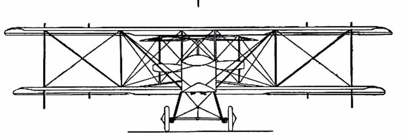
 showing the position of the body and the construction of the landing gear.") Grahame-White Military Biplane - front view
Grahame-White Military Biplane - front view
showing the position of the body and the construction of the landing gear.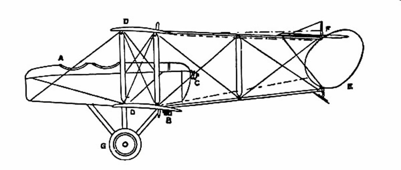
 showing shape and spread of planes and tail, and position of pilot and passenger.") Grahame-White Military Biplane
Grahame-White Military Biplane
showing shape and spread of planes and tail, and position of pilot and passenger.
") Galileo and the Well-sinkers
Galileo and the Well-sinkers