


 Another ardent worker in England, and one destined to become famous, was Mr. S. F. Cody. After devel...") The Cody Biplane
The Cody Biplane
Another ardent worker in England, and one destined to become famous, was Mr. S. F. Cody. After developing a system of man-lifting kites which the British War Office acquired, he joined the military aircraft factory that had been established at Farnborough. Here, after tests with dirigible balloons, he began the construction of experimental biplanes—all machines of large size. Early in 1909 he made brief flights—the longest being one of about 250 yards. Then, after alterations to his machine, he managed in July to fly a distance of 4 miles. This he increased afterwards to 8 miles; and then on 1st September flew for 1 hour 3 minutes, rising to a height of 300 feet. Cody’s biplane was a very large machine, having 1000 square feet of lifting surface—twice that of the Farman or Voisin. Driving it was an 80-h.p. engine, which operated two propellers on the system used by the Wrights. With its pilot on board the machine weighed 2170 lbs. A. Elevating-planes and vertical-plane B. Pilot’s control lever C.C. Main-planes D. Motor E. Propellers F. Rudder G. Landing gear H. Rear skid. showing the large size of the elevators, the position of the pilot, and the placing of the propeller...") The Cody Biplane from above
The Cody Biplane from above
showing the large size of the elevators, the position of the pilot, and the placing of the propellers. A.A. Ballast bags filled with sand
B. Instruments (such as a statoscope, which shows at any moment ...") The car of a modern Balloon
The car of a modern Balloon
A.A. Ballast bags filled with sand B. Instruments (such as a statoscope, which shows at any moment whether the balloon is rising or falling; and an altitude meter) C. Ring by which car is attached to balloon. Hence there is a type of fast scouting monoplane, in which a pilot can ascend alone, and fly at 100 ...") Single-seated Air Scout
Single-seated Air Scout
Hence there is a type of fast scouting monoplane, in which a pilot can ascend alone, and fly at 100 miles an hour. With such a craft, sweeping rapidly above an enemy’s position, the pilot-observer can return with his information at surprising speed. In the figure an air-scout of this type is seen. The tapering, covered-in body will be observed; this is to reduce wind resistance as the machine rushes through the air. The Gnome engine is, for the same reason, covered by an aluminium shield, which only allows the lower cylinders to project; they must, of course, be exposed in some way to the air, or they would not cool themselves. The landing-carriage has been reduced to its simplest form; this, again, is to reduce wind resistance; and the pilot, sitting deep in the body, shows only his head as the machine flies. Here, again, apart from the greater comfort in being so shielded, the placing of the pilot within the machine spells a lessening of pressure. A. Propeller B. Motor (partly hidden by shield) C. Pilot’s seat D. Sustaining plane E. Rudder F. Elevating-plane G. Chassis. But as airships were built larger, and greater speeds were obtained, it became necessary to strength...") Semi-rigid Airship
Semi-rigid Airship
But as airships were built larger, and greater speeds were obtained, it became necessary to strengthen the envelopes with some form of keel; and this led to a type which is known as the semi-rigid, and is developed successfully in France. The figure illustrates an airship of this build. Along the lower side of its envelope is placed a light, rigid framework or keel, and from this is suspended the car which contains engines and crew. A. Gas-containing envelope B. Strengthening keel C.C. Stabilising-planes D. Rudder E. Car carrying engines, propeller, and crew. A coastal sea-plane, as now planned, is a craft having, say, two engines, each devolving 120 h.p., w...") Sea-plane to carry a crew of seven
Sea-plane to carry a crew of seven
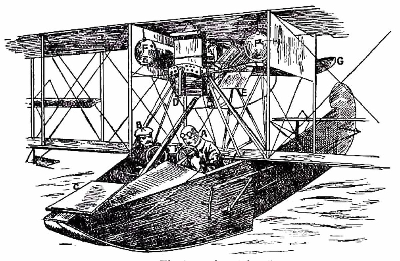
A coastal sea-plane, as now planned, is a craft having, say, two engines, each devolving 120 h.p., with a wing span of some 80 feet, and an accommodation in its hull for three men—the pilot, a combatant with a machine-gun, and an observer with an installation of wireless. But types are changing constantly, and the tendency is to build larger craft. A machine weighing a couple of tons is shown, and a novelty in regard to it is that it has wheels upon either side of its boat-shaped car, upon which it can move on land, and which fold upward when it rests upon the water. A. Hull upon which the machine floats when in the sea B.B.B. Wheels upon which it may move when on land, and which fold upward when it is on the water C. Pilot’s controlling wheel D.D. Main sustaining planes E. Four-bladed propeller driven by chain-gearing from engine within the hull. To meet the demand for a purely scouting machine, in which pilot and passenger shall have a clear fi...") Scouting Monoplane, with occupants below the wings.
Scouting Monoplane, with occupants below the wings.
To meet the demand for a purely scouting machine, in which pilot and passenger shall have a clear field for observation, both above and below, a monoplane has been designed which is called the “parasol.” This machine, a Morane-Saulnier, is shown. The two sustaining wings, forming a single surface, are raised above the body so that its occupants have nothing to impede their view earthward; and they can also see above them—an advantage of course in time of war, seeing that an enemy might be hovering overhead A. Engine and propeller B. Plane raised above hull C. Seats for pilot and passenger D. Rudder E. Elevating-plane. When petrol engines became available, they gave an impetus to the building of airships; for, like th...") Santos-Dumont’s Airship
Santos-Dumont’s Airship
When petrol engines became available, they gave an impetus to the building of airships; for, like the aeroplane, the airship needed a motive agent which gives a high power for a low weight. One of the first to use a petrol motor in an airship with success was M. Santos-Dumont, whose name has been mentioned in connection with aeroplanes. He tested small, light airships, driven by petrol engines and two-bladed propellers—as illustrated in figure; and with one of these, on a calm, still day, he flew over Paris and round the Eiffel Tower. A. Gas envelope B. Wheeled framework which carried motor, propeller, and pilot’s seat C. Elevating-plane D. Horizontal rear-plane E. Rudder. The fitting of several motors has been shown to be practical; and it has the obvious advantage that,...") Multiple-engined craft
Multiple-engined craft
The fitting of several motors has been shown to be practical; and it has the obvious advantage that, should one fail while in the air, the other or others will maintain a craft in flight. In such a machine as would fly the Atlantic, for example, it is proposed to fit four motors developing 800 h.p., and to carry a couple of mechanics who would constantly be tending them. Thus, should one engine develop trouble, its repair could be effected without descent, and with no worse result than a temporary fall in speed. In the figure is shown a method by which three Gnome motors may be fitted to a biplane. A. First engine (a 50-h.p. Gnome) B. Second engine (which is on the same shaft, but will run independently) C. Third Gnome engine, also an independent unit D. Four-bladed propeller (mounted higher than the crank-shaft bearing the engines, and driven by a chain gearing). (Early Type)
A. Elevating-plane
B. Seats for pilot and passenger
C. Main-planes
D. Motor with...") Maurice Farman Biplane
Maurice Farman Biplane
(Early Type) A. Elevating-plane B. Seats for pilot and passenger C. Main-planes D. Motor with two-bladed propeller E. Vertical panel F. Aileron G. Tail-planes H. Rudders I. Landing chassis. “Looping the loop,” which has made so great a sensation, has taught airmen one definite lesson; ...") Looping the loop
Looping the loop
“Looping the loop,” which has made so great a sensation, has taught airmen one definite lesson; and it is this: no matter how their machines may be beaten and tossed by the wind, they need not fear a fall—provided they are high enough above ground. The movements of a machine, as it makes a series of “loops,” are shown in the figure. The pilot reaches a high speed before he rears up his machine to begin the “loop,” and this downward velocity is attained by diving; then, when he estimates his pace sufficient, he pulls his elevating-lever back and the machine leaps upward, rearing itself vertically towards the sky, turning over on its back, then diving again and coming right-side-up—thus achieving a complete somersault. A skilled trick-flyer, also, will allow his machine to drop sideways or tail first, deliberately working the controls so that it shall do so. Then, just as it seems to spectators that he is falling to destruction, he will dive or twist, regain the mastery of his machine, and descend in a normal glide. There is a type of aeroplane which will be carried to sea when a fleet sails, stowed in sections wit...") Launching sea-planes from a ship’s deck
Launching sea-planes from a ship’s deck
There is a type of aeroplane which will be carried to sea when a fleet sails, stowed in sections within the hull of a transport ship. This machine—a light, high-speed craft—will be assembled upon the deck of its parent ship, and launched into the air by special mechanism, as there is not room for a machine to run upon wheels, and leave the ship’s deck as it might do upon land; the vessel, besides, might be rolling in a high sea. In some cases a platform is built upon the deck, either at the bow or stern, and along this the aircraft moves, so as to gain speed for its planes to lift. In one device, seen in Figure, the machine is mounted upon a light wheeled cradle, and this is placed upon the starting-rail. Then, driven by its propeller, the plane runs forward upon the cradle till it reaches the end of the rail, when it glides into the air, the cradle falling from it and dropping into the sea, from which it is retrieved and drawn back on board the ship. The sea-plane (A.) is seen taking flight, having glided upon its cradle along the platform (B.). The cradle (C.) is just falling away below the aircraft’s hull. By another method, shown in figure, the sea-plane is launched from a cable suspended between two mas...") Launching a sea-plane from a wire
Launching a sea-plane from a wire
By another method, shown in figure, the sea-plane is launched from a cable suspended between two masts, and can come to rest upon the cable again after a flight has been made. The machine is hung upon the cable prior to making an ascent; then the pilot starts his engine, and as his machine glides forward along the cable he releases a catch and soars into the air. Upon returning he flies beneath the cable, and makes his craft rise until the “V”-shaped apparatus above his head is caught by the cable and the catch becomes operative; then he stops his motor, and his craft hangs from the cable as it did before. A. Sea-plane B. Cable C. The “V”-shaped apparatus which guides the cable into the clip (D.) and so suspends the machine from the wire. Hull of a Zeppelin during construction.
Craft of the semi-rigid type provide a link between small...") Hull of a Zeppelin during construction
Hull of a Zeppelin during construction
Hull of a Zeppelin during construction. Craft of the semi-rigid type provide a link between small, non-rigid ships and the very large machine which is built with an entirely rigid framework, and has its example in the Zeppelin. The maker forms a skeleton hull of aluminium or some light metal alloy, a method that is shown in figure. The hull of a Zeppelin, slightly more than 500 feet in length, is sheathed with tightly stretched fabric; and within it are the gas-containers—a row of seventeen separate balloons, each in a compartment by itself, and containing a total of nearly 1,000,000 cubic feet of gas—which give these airships a lifting power of close upon 30 tons. showing shape and spread of planes and tail, and position of pilot and passenger.") Grahame-White Military Biplane
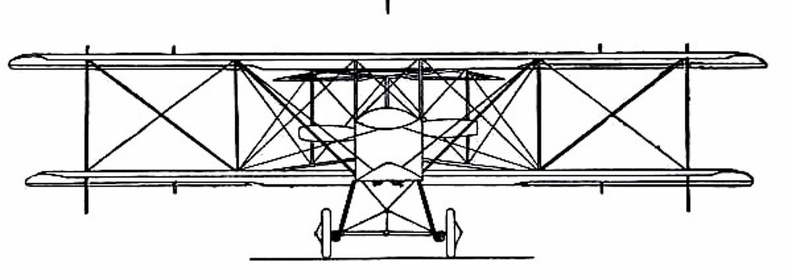
Grahame-White Military Biplane
showing shape and spread of planes and tail, and position of pilot and passenger.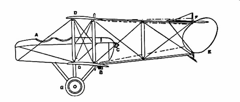
- Grahame-White Military Biplane - side view
Once the value of aerial reconnaissance had been proved, France proceeded to the development of a scouting aeroplane; and the need, in such a machine, is that the observer shall have a clear view ahead and below. The construction of machines was, for this reason, modified. The front elevating plane was moved to the rear, where it was fitted in the form of a flap—as in the case of monoplanes—and the pilot and observer placed in a covered-in body, which projected in front of the main-planes, as shown in the figure. By placing the body before the planes, the observer has a clear view ahead and on either side; and even when he leans over the side, and looks directly downward, there is no surface to obstruct him. A. Covered-in body, with seats for pilot and passenger B. Motor (to minimise wind resistance, only the lower cylinders are exposed to the air) C. Propeller D. Main-planes E. Rudder F. Elevator G. Landing gear.
- Grahame-White Military Biplane - front view
showing the position of the body and the construction of the landing gear.
 A typical craft, representing the first of those navigated with any certainty, is shown in Figure. A...") Early-type Airship
Early-type Airship
A typical craft, representing the first of those navigated with any certainty, is shown in Figure. A gas-containing envelope, made of a light, strong, varnished fabric, is kept taut by the pressure of the gas within; the car, constructed of wood or metal tubing, is suspended by ropes from the envelope, and contains engine and crew, with a two-bladed propeller revolving astern. Such a machine, in its control, had an elevating-plane and rudder, upon the same principle as those of the aeroplane. One of the difficulties to be overcome was the expansion and contraction of gas in the envelope owing to differences in altitude and temperature. When the craft ascended, its envelope completely inflated, the gas began to dilate owing to the outer air becoming less dense; and some had to be allowed to escape through automatic valves. Then, should the machine descend to a lower level, there was not sufficient gas in the envelope to keep it tightly stretched, and it tended to sag at the bow as it was driven through the air. A. Gas envelope B. Car suspended below envelope C. Motor, which drives propeller (D) through a shaft E. Small horizontal plane for rising or descending F. Fixed fin, or keel plane, to give stability G. Rudder. Another machine which is stable in flight, owing to the peculiar formation of its wings, which resis...") Dunne inherently stable Biplane
Dunne inherently stable Biplane
Another machine which is stable in flight, owing to the peculiar formation of its wings, which resist a diving or plunging movement, or a lateral swing, is the Dunne biplane—as designed by Lieutenant J. W. Dunne. This craft is seen in the figure. Using such a machine, pilots have flown for long distances with the control levers locked, the biplane adapting itself automatically to the wind-gusts and preserving its equilibrium without aid of any kind. It has neither fore-plane nor tail; it is made to ascend by elevators which are in the form of hinged flaps, or ailerons, and is steered by two rudders at the extremities of the main-planes. A. Hull containing pilot and passenger B.B. Main-planes C.C.C.C. Flaps used as elevators D.D. Side-planes which act as rudders E. Engine and propeller F. Alighting gear.") Driving-seat of a touring plane
Driving-seat of a touring plane Biplane (541 visites) A. Hull, which is steel-built, containing pilot and passenger
B. Main-planes—the lower at a dihed...") D.F.W. (German-designed) Biplane
D.F.W. (German-designed) Biplane
A. Hull, which is steel-built, containing pilot and passenger B. Main-planes—the lower at a dihedral angle C. Uptilted stabilising ailerons, which may be locked in position D. Stabilising fin E. Rudder F. Elevating-plane G. 100-h.p. motor (which is enclosed) and propeller. A. Wheels operating elevating-planes and rudder
B. Height recorder
C. Speaking-tube to communicate...") Control platform of an Airship
Control platform of an Airship
A. Wheels operating elevating-planes and rudder B. Height recorder C. Speaking-tube to communicate with engineers. A. Lower part of aeroplane’s hull
B. Revolving barrel to which bombs are clipped
C. Bombs
D. Re...") Bomb-releasing mechanism
Bomb-releasing mechanism
A. Lower part of aeroplane’s hull B. Revolving barrel to which bombs are clipped C. Bombs D. Releasing mechanism operated by marksman in machine. Bombs may be carried and dropped when opportunity offers; and as an improvement upon the early method, which was simply to throw these from the machine, there are releasing mechanisms now devised which carry a number of projectiles and drop them one by one as a lever is moved. The bombs, which are long, pointed, and balanced so that they will fall head first, are clipped round a barrel rather like that of a revolver, which is fixed beneath the aeroplane’s hull just below the occupants’ seat. Mechanism causes the carrying chamber to revolve and bring each bomb against a releasing catch, which—at a movement of the marksman’s lever—throws it outwards and downward. Coal-gas superseded hot air in the filling of balloons, the latter being unsatisfactory, seeing that...") A modern Balloon
A modern Balloon
Coal-gas superseded hot air in the filling of balloons, the latter being unsatisfactory, seeing that it cooled rapidly and allowed the balloon to descend; the only alternative being to do what some of the first aeronauts did, and burn a fire below the neck of their balloon even when in the air. But the dangers of this were great, seeing that the whole envelope might easily become ignited. With balloons filled with coal-gas long flights were possible, but they had always this disadvantage—the voyagers were at the mercy of the wind, and could not fly in any direction they might choose. If the wind blew from the north then they were driven south, the balloon being a bubble in the air, wafted by every gust. Aeronauts became disgusted with this inability to guide the flight of a balloon, and many quaint controls were tested; such, for example, as the use of a large pair of oars with which the balloonist, sitting in the car of his craft, rowed vigorously in the air. showing the span of the main-planes, and the curve of the boat-shaped hull.") A Flying Boat
A Flying Boat
showing the span of the main-planes, and the curve of the boat-shaped hull.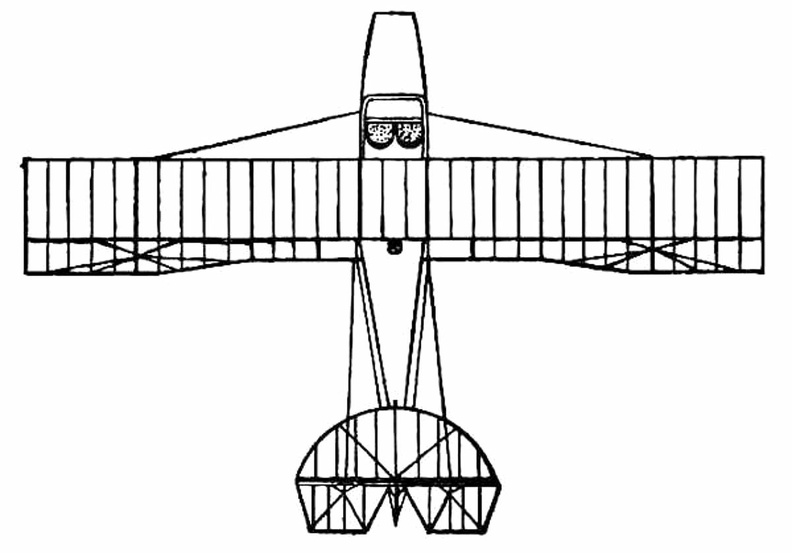
- A Flying Boat top view
showing the shape of wings and tail, and the positions of the pilot and passenger within the hull.
- A Flying Boat - side view
A. Hull B. seats for crew C. Planes D. Motor E. Propeller F. Rudder G. Elevators.
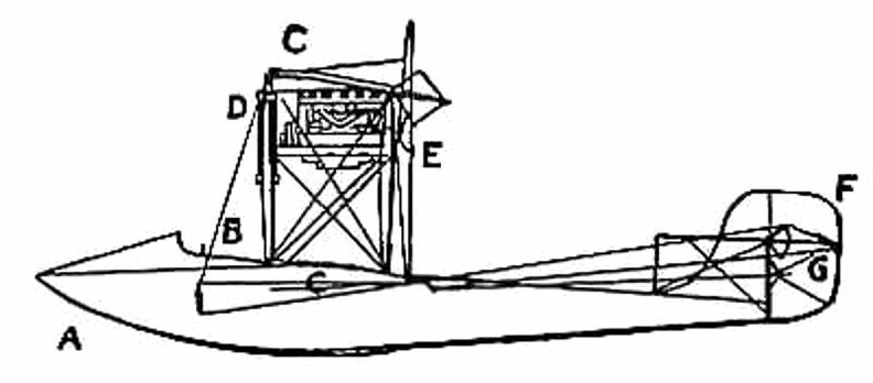
 England, in the building and handling of sea-planes has come well to the fore, and our machines are ...") A Bleriot Sea-plane
A Bleriot Sea-plane
England, in the building and handling of sea-planes has come well to the fore, and our machines are more advanced than those of other countries. The Admiralty has recognised that, acting as a coastal scout in time of war, such craft would be of the utmost value; thus we find air-stations dotted round our seaboard, from which machines may fly in a regular patrol. By the employment of hundreds of craft, operating upon a well-ordered plan, it will be possible in the future to girdle our shores completely; and such machines would not only spy out the approach of an enemy’s fleet, but give battle to hostile aeroplanes or airships which might seek to pass inland. The type of machine we have just described was a biplane, but there are monoplane sea-craft, and a Bleriot fitted for alighting upon the water is shown. ...it was followed in due course by the use of small steam engines and electric motors, which were ...") An Experimental Airship
An Experimental Airship
...it was followed in due course by the use of small steam engines and electric motors, which were made to turn propellers such as are used in aeroplanes. For such experimental craft, the rounded form of gas-container was abandoned and a cigar-shaped envelope adopted, pointed at both ends, which could be more easily driven through the air. An airship of a crude and early type is seen here. It was built by an experimenter named Gifford, and in 1852 it flew at the rate of seven miles an hour. A. Gas-containing envelope; B. Car suspended below envelope, which carried the aeronaut and a 3-horse-power steam engine; C. Two-bladed propeller driven by the engine; D. Rudder (in the form of a sail) by which the machine could be steered from side to side. The sea-plane, when a flight is made, is launched upon the water down a slipway; then the pilot and ...") An Avro Sea-Plane
An Avro Sea-Plane
The sea-plane, when a flight is made, is launched upon the water down a slipway; then the pilot and his passenger embark, the motor is started, and the propeller draws the machine across the water at a rapidly increasing pace. The floats raise themselves higher and higher upon the water, as the air-planes exercise a growing lift, until they only just skim the surface. And now comes the moment when the airman, drawing back his elevating lever, seeks to raise his craft from the water into the air. At first only the front of the floats rise, the rear sections clinging to the surface; then, in another instant, the whole float frees itself from the water in a scatter of spray, and the craft glides at a gently-sloping angle into the air. It is the aim of builders, by the curve they impart, to make the floats leave the water with as little resistance as possible. In the floats of the Avro will be noticed a notch, or cut-away section, which occurs at about the centre of the float upon its lower side. This is called a “step,” and is to help the float to lift from the water. When the main-planes draw upward, as the craft moves prior to its flight, the floats tend, as has been said, to raise themselves in the water; and as they do so, lifting first towards the bow, there comes a space between the upward-cut “step” and the surface of the water. Into this space air finds its way and, by helping still further to free the float from the surface, aids greatly at the moment when the pilot—operating his hand-lever—seeks the final lift which will carry him aloft. A. Propeller B. 100-h.p. Gnome motor, hidden by shield C. Main-planes D. Observer’s seat E. Pilot’s seat F. Rudder G. Elevating-plane H. Float to support tail I. Main floats to bear the weight of the machine. An Airship leaving its shed
A. The machine emerging stern first
B. A sister craft in dock
C. Th...") An Airship leaving its shed
An Airship leaving its shed
An Airship leaving its shed A. The machine emerging stern first B. A sister craft in dock C. The launching crews D. Rails upon which the cars of the airship move, so as to prevent its swinging sideways in a gust E. Outlook station upon the roof of the shed F. Workshops; living quarters for the crews; plant for making hydrogen gas. Airships, like aeroplanes, are being armed with guns and bombs; and their power of raising weights e...") Aeroplanes attacking an airship from above
Aeroplanes attacking an airship from above
Airships, like aeroplanes, are being armed with guns and bombs; and their power of raising weights enables them to carry heavy weapons. Large and highly destructive bombs have been tested in the German airships, being released over the sea and aimed at targets in the form of rafts. Latest-type airships also carry guns in their cars; and the Zeppelins have a platform upon the tops of their hulls, reached by a ladder through the middle of the ship, from which a machine-gun can be fired upward. This is a very necessary precaution, and is intended to frustrate the attack of an aeroplane. It would be the aim of the latter, whenever possible, to manœuvre above its big enemy—as suggested in figure —and drop a bomb upon its hull. Hence the construction of the top platform of the airship, from which her gunners can direct a vigorous fire aloft. Air-racing, as made popular by the proprietors of the Hendon aerodrome, forms so fascinating a sight...") A pylon, or mark-tower, on the flying track
A pylon, or mark-tower, on the flying track
Air-racing, as made popular by the proprietors of the Hendon aerodrome, forms so fascinating a sight that, on a day of public holiday, as many as 50,000 people will assemble in the enclosures. To stand near one of the pylons—wooden towers which mark the turning-points of the course—and see the air-racers come rushing by, is to gain such an impression of speed as almost makes the watcher hold his breath. The pilot in a flying race has one chief aim: to fly the shortest way. Every fraction of a second is of importance; and if he can circle the pylons more skilfully than his rivals, he may win the race, even though his machine—in its actual speed—may be no faster than theirs. We present a bicycle for ladies, lately invented and patented by Messrs. Pickering & Davis of New Yo...") Velocipede for Ladies
Velocipede for Ladies
We present a bicycle for ladies, lately invented and patented by Messrs. Pickering & Davis of New York City. It will be seen that the reach or frame, instead of forming a nearly straight line from the front swivel to the hind axle, follows the curve of the front wheel until it reaches a line nearly as low as the hind axle when it runs horizontally to that point of the hind wheel. The two wheels being separated three or four inches, allow of an upright rod being secured to the reach; around this is a spiral spring, on which a comfortable, cane-seated, willow-backed chair is placed. This machine, with a moderate-sized wheel (of thirty to thirty-three inches), will allow being driven with a great deal of comfort and all the advantages of the two-wheel veloce. In mounting, a lady has to step over the reach, at a point only twelve inches from the floor, the height of an ordinary step in a flight of stairs. We present an engraving of an English one-wheeled velocipede. The feet are placed on short stilts, c...") English one-wheeled Velocipede
English one-wheeled Velocipede
We present an engraving of an English one-wheeled velocipede. The feet are placed on short stilts, connected with the cranks, one on either side of the rim, while the rider sits upon a steel spring saddle over the whole wheel. The inventor modestly limits the diameter of the wheel to twelve feet, and the number of revolutions to fifty per minute. Twenty-five miles per hour is the speed expected to be reached. The riders of this machine, without the ability to overcome the laws of gravity, would be very likely to get broken bones and noses. It is not likely to come into general use. HEMMING'S UNICYCLE, or \"FLYING YANKEE VELOCIPEDE.\"
The single-wheeled velocipede has at length ...") Flying Yankee Velocipede
Flying Yankee Velocipede
HEMMING'S UNICYCLE, or "FLYING YANKEE VELOCIPEDE." The single-wheeled velocipede has at length received a palpable body, and " a local habitation and a name." Richard C. Hemming of New Haven, Conn., invented the machine herewith represented, two years ago; but has only recently brought it into the market and applied it to practical purposes.. The main wheel has a double rim, or has two concentric rims, the inner face of the inner one having a projecting lip for keeping the friction rollers and the friction driver in place; each of these being correspondingly grooved on their peripheries. The frame on which the rider sits, sustains these friction wheels in double parallel arms, on the front one of which is mounted a double pulley, with belts passing to small pulleys on the axis of the driving wheel. This double wheel driven, as seen, by cranks turned by the hands. The friction of the lower wheel on the surface of the inner rim of the main wheel is the immediate means of propulsion. A small binding wheel, seen between the rider's legs, serves to keep the bands or belts tight. The steering is effected either by inclining the body to one side or the other, or by the foot impinging on the ground, the stirrups being hung low for this purpose. By throwing the weight on these stirrups, the binding wheel may be brought more powerfully down on the belts. Over the rider's head is an awning, and there is also a shield in front of his body to keep the clothes from being soiled by mud and wet. When going forward, the driving wheel is kept slightly forward of the centre of gravity by the position of the rider. By this means the power exerted is comparatively small. Every turn of the crank is equivalent to a rotation of the great wheel. Mr. Hemming says that this machine can be manufactured for fifty dollars, of a weight of only thirty pounds;- that it will ascend steep grades, and that it can be driven on the roads with but little exertion, at the rate of twenty or even twenty-five miles an hour. This wheel is of a diameter of from six to eight feet. Mr. Hemming's boy of thirteen has one five feet in diameter, the first manufactured, crude in construction, and heavier than necessary, which he propels at the rate of a mile in three minutes.
This velocipede was patented January 5th, 1869. It has been thoroughly tested and is pronounced a ...") Callihan's Velocipede
Callihan's Velocipede
This velocipede was patented January 5th, 1869. It has been thoroughly tested and is pronounced a complete success. It will be seen that it is very different from Bradford's machine. The front wheels are used as guiding wheels, the rear as the driving ones. It is propelled by both hands and feet, acting together or separately. The propelling power is almost unlimited, and is furnished by cranks in the hind axles, with lever attachments. It has three different steering arrangements, either of which can be applied, according to the taste of the purchaser. In all these, the forward wheel and axle are turned with a lever arrangement, operated upon by the band. The machine develops both chest and limbs, and can be readily used by ladies and children. A little girl of six years has ridden it for an hour without fatigue. It is so constructed, that scruples of delicacy need prevent no lady from driving it. It can be driven either backwards or forwards, will run upon the road, at the rate of fifteen miles an hour, and will ascend any ordinary hill with ease. It is claimed, that it is the only machine made that can be checked in going down hill, or that can be stopped instantly. The machine varies in size and weight. That most in favor, has a wheel of three feet and a half in diameter, and a weight of about one hundred pounds. It is constructed of the best material, and is neat and nobby in appearance. Its price is $125. If any of our readers desire the luxury of a ride on a velocipede without the necessity of taking le...") Bradford's Velocipede
Bradford's Velocipede
If any of our readers desire the luxury of a ride on a velocipede without the necessity of taking lessons, or the danger of getting a fall, they will find " Bradford's Four-Wheeled Velocipede" ready and able to afford them the pleasure. The inventor of this vehicle, Mr. C. K. Bradford, has devoted the greater part of the last five years to experiments upon the velocipede, and took out his first patent three years and a half ago. The machine, as now constructed and improved, obtained its American patent October 13th, 1868. It has since been patented in England, France, and Belgium. It is made of the best material, and finished like a gentleman's trotting wagon. It weighs but sixty-five pounds, and combines in a high degree both lightness and strength. Any man, woman or child, can learn to guide it easily with but a few moments practice. The inventor claims that it is able to maintain a speed of a mile in three minutes, and that the extraordinary time of a half mile in one minute and forty-five seconds, has been made upon a country road. It can be driven by almost any man, at the rate of a mile in four minutes, on almost any road, without greater exertion than is ordinarily used in walking. This velocipede, unlike all others, is seen to best advantage on the street. In Mr. Bradford's tasteful little curricle, the rider can sit at ease as carelessly as in a carriage, giving himself up wholly to the exhilaration of the rapid movement, and the pleasurable exercise of the muscles, which is just enough to make the machine skim over the ground, and give an enjoyable sense of power. The increase of friction, which would naturally result from the additional number of wheels, is prevented by an application of anti-friction rollers, which reduce the labor of propelling the machine to a minimum, a requisite of the highest importance to a person seeking either recreation or utility. As will be seen from the accompanying engraving, \"Pickering's American Velocipede,\" manufactured by ...") Pickering's American Velocipede
Pickering's American Velocipede
As will be seen from the accompanying engraving, "Pickering's American Velocipede," manufactured by Messrs. Pickering & Davis, differs very materially from the French model, so generally used by other manufacturers. It is claimed that it is more simple and durable, lighter and stronger. The reach or frame of this velocipede is made of hydraulic tubing. The gun-metal bearings are so attached that, when worn, they may be replaced by others, which are interchangeable like the parts of sewing-machines and fire-arms. The axle is so constructed as to constitute, in itself, an oil box. It is made tubular, and closed at either end with a screw, on the removal of which it is filled with lard oil. Cotton lamp-wick is placed loosely in the tubular axle and the oil is by this means fed to the bearing, as fast as required, through the small holes made for the purpose in the centre of the axle. The saddle is supported on a spiral spring, giving an elastic seat; it is brought well back, so that the rider maintains an erect position, and is adjustable to suit the length of limb of the rider. The tiller or steering handle is constructed with a spring so that the hands are relieved from the jolting that they would otherwise receive while running over rough ground. The stirrups or crank pedals, are three-sided, with circular flanges at each end, fitted to turn on the crank pins, so that the pressure of the foot will always bring one of the three sides into proper position. They are so shaped as to allow of the use of the forepart of the foot, bringing the ankle joint into play, relieving the knee, and rendering propulsion easier than when the shank of the foot alone is used. The connecting apparatus differs from that of the French vehicle in that the saddle bar serves only as a seat and brake, and is not attached to the rear wheel. By a simple pressure forward against the tiller, and a backward pressure against the tail of the saddle, the saddle spring is compressed, and the brake attached to it brought firmly down against the wheel. Messrs. Pickering & Davis have a large manufactory, and are the constant recipients of orders from all parts of the country. Mr. Pickering has always been a practical machinist, and personally superintends the structure of each machine turned out.
The accompanying engraving will convey to the mind of the reader a correct idea of the French two-...") Construction of the Bicycle
Construction of the Bicycle
The accompanying engraving will convey to the mind of the reader a correct idea of the French two-wheeled velocipede. The majority of makers in this country fashion their machine upon this pattern in every essential respect. We append a full technical description. A is the front wheel. This is the steering wheel, and upon its axis, the power is applied. B is the hind wheel; C, the treadles or foot-pieces ; D, the treadle cranks; E, slots in cranks, by which to adjust the foot-pieces and accommodate the length to the legs of the rider; F, bifurcated jaw, the lower part of which forms the bearing for the axle of the front wheel. From the upper part of this jaw, a rod or pivot extends, to which is attached the steering arm or handle F; G, the reach or perch, extending from the jaw of the front wheel to the rear or hind wheel. This reach is bifurcated, forming jaws for the hind wheel. H, " rests" on the front part of the reach. The rider puts one leg on the rest and works one of the cranks with the other leg while riding " side-saddle," or a leg may be placed upon each rest when the velocipede has acquired sufficient momentum, and the rider does not wish to keep his feet upon the treadles. I, the saddle or seat, which is adjustable on the seat-spring L, by the thumb-screw K. The seat-spring L, is attached at M to the reach G, which, at the other end, is fastened to the spring-struts N, that rise from the reach G; 0, the brake-lever, on the fulcrum P; Q,, the " shoe " of the brake that acts against the periphery of the hind wheel. The brake is operated by means of the cord S, one end of which is attached to the steering handle F, and the other end to the reach at 3. A cord passes from the steering handle under the pulley or roller 4, thence over the pulley 5, on the brake-lever 0, and from there to the point 3, where it is attached to the reach G. The brake is operated by giving a slight turning motion to the handle F, thus winding a small sheave upon the axis of the handle, and bring-ing the shoe Q, of the brake-lever 0, in contact with the surface of the wheel B. Of the various kinds of velocipedes, four, three, two, and one wheeled, the bicycle seems to be cons...") The Bicycle
The Bicycle
Of the various kinds of velocipedes, four, three, two, and one wheeled, the bicycle seems to be considered the most artistic, is altogether the most in favor, and steadily maintains its ground against all rivals. Whether it will be the model velocipede of the future remains to be seen. The various experiments now being tried will, no doubt, eventually result in a nearly perfect machine, but it will require a season's experience fully to develop the ingenuity of our American artisans. Many have expressed doubts as to the real utility of the velocipede, and the permanency of its use. They seem to think it a frivolous invention only calculated to serve purposes of amusement, and soon to be superseded by some other ephemeral claimant for popularity. Most of these have based their opinions upon the disuse into which rude machines have fallen in former times. But the difference in the construction of the modern velocipede from the primitive one has entirely changed the character of the vehicle. It is no longer a draft vehicle, but a locomotive, and as much superior to the original bar on wheels, as the improved steam locomotive is to the old-time stage-coach. Drasina
This novel vehicle, under the name of \" Drasina was introduced into England in 1818, and, a...") Drasina
Drasina
Drasina This novel vehicle, under the name of " Drasina was introduced into England in 1818, and, at first, the greatest possible expectations were created, with regard to its usefulness and speed. It was maintained, that it would travel up-hill on a post-road as fast as a man could walk ; that on a level, even after a heavy rain, it would average six or seven miles an hour ; and that, on a descent, it would equal a horse at fall speed. It was described in the advertisements of the day as " consisting of two wheels, one behind the other, connected by a perch, on which a saddle is placed as a seat. The front wheel is made to turn on a pivot, guided by a circular lever or rudder, which comes op to the hand; the fore-arms rest on a cushion in front ; in this position, both hands holding the rudder firmly, the machine and traveller are preserved in equilibrio. In 1821 Lewis Gomperta of Surrey, introduced some decided improvements upon the Drasina , as will be seen from the accompanying engraving. The object of the improvement of Gomperta was to bring the arms of the rider into action, in assist-ance to his legs. It consisted " in the application of a handle, C, which is to be worked backwards and forwards, to which is attached a circular rack, D G, which works in a pinion, E, with ratch wheel on the ont wheel of the velocipede, and which, on being pulled by the rider with both hands, sends the machine forward; and when thrust from him does not send it back again, on account of the ratch, which allows the pinion to turn in that direction, free of the wheel. H is the saddle, and the rest, B is so made that the breast of the rider bears against it, while the sides come around him at some distance below the arms, and is stuffed." The rider could with this machine either propel it entirely without the feet, or he could use the feet, while the arms were free. The beam, A, was made of beech wood, and a pivot at F, allowed the front wheel to be turned to the right or left at the will of the rider. The article upon the Velocipede in the \" American Encyclopedia,\" commences by giving the well-known ...") Velocipedes
Velocipedes
The article upon the Velocipede in the " American Encyclopedia," commences by giving the well-known derivation of the word from the Latin velox, swift, and pes, a foot, and defines it as a carriage, by means of which the rider propels himself along the ground, and states that it was invented at Manheim. I will now give you a sectional division of a first-rate line-of-battle ship. Such a ship, carrying ...") Section of First-rate Man-of-War
Section of First-rate Man-of-War
I will now give you a sectional division of a first-rate line-of-battle ship. Such a ship, carrying 120 or more guns, has four decks on which her guns are placed. The highest is open to the air, and is called the UPPER DECK At the after part, extending a little way beyond the mizen-mast, there is a raised platform, called the POOP. It has no guns on it. On the main deck is the steering-wheel, with the binnacle in front of it. The after part of this deck between the poop and the main-mast is called the quarter-deck, and is the place where the officers especially walk. The part under the poop is divided into cabins, appropriated to the use of the captain. Here, also, is a clerk's office and a pantry. Between the main and fore-mast the large boats are stowed, and on either side are the gangways at which sentries are stationed. The next deck under this is called the MAIN DECK. In the after part is the admiral's cabin. Immediately under the boats is a pen for the officers' live-stock ; and just abaft the fore-mast is the galley, or kitchen. The third deck from the upper is called the MIDDLE DECK. The after part is fitted up for the lieutenants, chaplain, surgeon, paymaster, marine officers, &c., and called the WARD-ROOM. In the fore part of the deck is placed the sick-bay, a compartment fitted up as a hospital ; about the centre of this deck is one of the capstans. The fourth from the upper is called the LOWER or GUN DECK. In the after part is the GUN-ROOM, where the midshipmen, and other junior officers, mess. The tiller of the rudder works through the gun-room just above their heads. A second capstan is placed on this deck ; and forward are the riding-bitts for securing the cables. It is the lowest deck on which guns are carried. The ORLOP DECK is the fifth deck from the upper. It has no guns or ports, though lighted up by bull's eyes or scuttles. In the after part is the purser's issue-room ; next to it is the after cockpit, where the midshipmen and other junior officers sleep in hammocks. Before it again will be found the sail-room, where the sails are kept, and the cable-tiers, where the cables are stowed. Before it again, just abaft the fore-mast, is the fore cockpit, and the warrant officers' cabins, while right in the head of the ship are the carpenter's and boatswain's stores. Low as we have got, we have still further to go down to the HOLD, which, if it may be so called, is the sixth deck from the highest. It is often divided into two decks for the greater convenience of stowage. Here are the FORE AND AFTER MAGAZINES, WATER TANKS, WINE AND SPIRIT ROOM, CHAIN CABLE LOCKERS, SHOT LOCKERS, BREAD ROOM, SHELL ROOM, GUNNER'S STORE ROOM, DRY PROVISION, and BEEF AND PORK IN CASKS. Since the introduction of auxiliary steam-power into ships of war, a large portion of the hold is devoted to the steam-engine and boilers, coal bunkers, and the shaft of the screw, while the funnel runs up through all the decks ; but it is wonderful, comparatively, how little space these are allowed to occupy, considering the great aid the steam-engine affords to the movements of the ship. Launched in 1863
Among the numerous huge monsters constituting the iron-clad fleet of England, ...") The 'Minotaur'
The 'Minotaur'
Launched in 1863 Among the numerous huge monsters constituting the iron-clad fleet of England, the Minotaur, is one of the most gigantic and formidable; and the sister ships, the Agincourt and Northumberland, all of precisely the same tonnage, power, rig, and equipment, are the largest and most powerful ships in the navy. The Minotaur was built at Blackwall, by the Thames Ship Building company and the engines were constructed by Messrs. Penn, of Deptford. She is 6,621 ton's measurement, and propelled by screw engins of 1,350 horsepower, with a speed of 15 knots an hour. She is 400 feet in length by 59 in width, and carries in all thirty-four of the heaviest guns used afloat. Among these which form her chief batter on the main deck are four 300-pounder Armstrongs. An aeroplane is a necessity in times of peace") An aeroplane is a necessity in times of peace
An aeroplane is a necessity in times of peace
An aeroplane is a necessity in times of peace German plane crashed into an American warship") A mass of wreckage that strikes the deck of one of our warships
A mass of wreckage that strikes the deck of one of our warships
German plane crashed into an American warship Air raid siren in Paris") Tooting the sirens of warning
Tooting the sirens of warning
Air raid siren in Paris British plane flying over the trenches in the great war") They swoop down over the trenches
They swoop down over the trenches
British plane flying over the trenches in the great war The seaplane shoots off the catapult") The seaplane shoots off the catapult
The seaplane shoots off the catapult
The seaplane shoots off the catapult The depth bomb destroys a U-Boat") The depth bomb destroys a U-Boat
The depth bomb destroys a U-Boat
The depth bomb destroys a U-Boat It was on June 5, 1783 that Stephen and Joseph Montgolfier, two French brothers, sent up the first b...") The ascension of Montgolfier’s balloon
The ascension of Montgolfier’s balloon
It was on June 5, 1783 that Stephen and Joseph Montgolfier, two French brothers, sent up the first balloon. You can just imagine the amazement it caused when it arose from the ground. Some types of American and foreign aeroplanes") Some types of American and foreign aeroplanes
Some types of American and foreign aeroplanes
Some types of American and foreign aeroplanes Some types of American and foreign aeroplanes") Some types of American and foreign aeroplanes
Some types of American and foreign aeroplanes
Some types of American and foreign aeroplanes Ship saved by life line thrown from a rescue airship
[Not sure what it did to save the boat]") Ship saved by life line thrown from a rescue airship
Ship saved by life line thrown from a rescue airship
Ship saved by life line thrown from a rescue airship [Not sure what it did to save the boat] (1401 visites) Scouting over the ruined region between the lines (no man’s land)") Scouting over the ruined region between the lines (no man’s land)
Scouting over the ruined region between the lines (no man’s land)
Scouting over the ruined region between the lines (no man’s land) Plane going down in flames") Plane going down in flames
Plane going down in flames
Plane going down in flames Pilot and passenger") Pilot and passenger
Pilot and passenger
Pilot and passenger Original Wright Biplane") Original Wright Biplane
Original Wright Biplane
Original Wright Biplane Naval battle with planes launched from ships") Naval battle with planes launched from ships
Naval battle with planes launched from ships
Naval battle with planes launched from ships